
Related Manuals for Metrologic MS7180 OrbitCG


Summary of Contents for Metrologic MS7180 OrbitCG
- Page 1 METROLOGIC INSTRUMENTS, INC. ® MS7180 OrbitCG Presentation Laser Scanner Installation and User’s Guide...
- Page 2 Copyright © 2008 by Metrologic Instruments, Inc. All rights reserved. No part of this work may be reproduced, transmitted, or stored in any form or by any means without prior written consent, except by reviewer, who may quote brief passages in a review, or provided for in the Copyright Act of 1976.
-
Page 3: Table Of Contents
ABLE OF ONTENTS Introduction Product Overview ..................... 1 Scanner and Accessories................. 2 Scanner Components..................4 Cable Removal....................4 Caution and Serial Number Labels..............5 Maintenance..................... 5 Mounting Specifications ................... 6 Installation RS232, or Light Pen ..................7 Keyboard Wedge....................9 Stand-Alone Keyboard Wedge ............... - Page 4 ABLE OF ONTENTS Design Specifications ..................27 Applications and Protocols ................. 29 Default Settings - Communication Parameters........... 30 Scanner Configuration..................35 Configuration Modes ..................35 Bar Codes ....................35 MetroSet2....................35 Serial Configuration ..................35 Upgrading the Firmware ..................36 Scanner and Cable Terminations Scanner Pinout Connections ................
-
Page 5: Product Overview
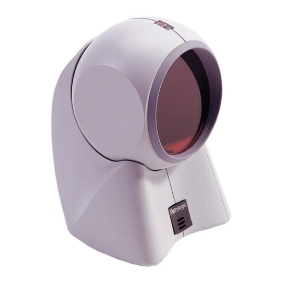
NTRODUCTION ® OrbitCG is an aggressive, omnidirectional laser bar code scanner ideal for use in retail, convenience, liquor and specialty stores Designed to be lightweight and rugged, OrbitCG’s small size makes it ideal for applications where counter space is limited. Its unique contoured shape allows it to be picked-up and used as a hand-held scanner when scanning large or bulky items. -
Page 6: Scanner And Accessories
Scanner and Accessories ASIC OMPONENTS Part No. Description MS7180 OrbitCG Presentation Laser Bar Code Scanner MS7180 OrbitCG Presentation Laser Bar Code Scanner 00-02284x Installation and User’s Guide ® 00-02407x MetroSelect Configuration Guide * Guides also available for download at www.metrologic.com. - Page 7 NTRODUCTION Scanner and Accessories PTIONAL CCESSORIES Part No. Description 59-59002x-3 Keyboard Wedge PowerLink Cable straight cord 59-59020x-3 Stand Alone Keyboard PowerLink Cable straight cord ™ USB Full Speed Cable, Locking Plus-Power Type A 54-54213x-N-3 straight cord ™ USB Full Speed Cable, Locking Plus-Power Type A straight cord 54-54214x-N-3...
-
Page 8: Scanner Components
NTRODUCTION Scanner Components ESCRIPTION Mode Select Button/CodeGate Button (see page 14) White LED (see page 17) Blue LED (see page 17) Red Output Window (Laser Aperture) Speaker (see page 17) 10-Pin RJ45, Female Socket (see page 39) Pin Hole for Cable Release Adjustable Scan Head Figure 1. -
Page 9: Caution And Serial Number Labels
NTRODUCTION Caution and Serial Number Labels Figure 3. Label Location on the Bottom of the Scanner with Example Caution To maintain compliance with applicable standards, all circuits connected to the scanner must meet the requirements for SELV (Safety Extra Low Voltage) according to EN/IEC 60950-1. To maintain compliance with standard CSA C22.2 No. -
Page 10: Mounting Specifications
NTRODUCTION Mounting Specifications Optional Wall/Counter Mount, MLPN 45-45619 Item Description Qty. Locking Plate, 50-50302 MLPN Base Cover, 50-50301 MLPN #7 x 1.00" Wood Screw, 18-18013 MLPN M3 x 8 mm Flathead Screw, 18-18004 Figure 4. Kit Components MLPN Drill three #39 pilot holes. Note the position OrbitCG will rest (see Figure 5). -
Page 11: Installation
NSTALLATION RS232, Light Pen Emulation Turn off the host device. Plug the male 10-pin RJ45 end of the PowerLink cable into the 10-pin socket on the MS7180. Connect the 9-pin female end of the PowerLink cable to the host device. Plug the external power supply into the power jack on the PowerLink cable. - Page 12 NSTALLATION RS485 Turn off the host device. Plug the male 10-pin RJ45 end of the MVC cable into the 10-pin socket on the MS7180. Connect the other end of the MVC cable to the host device. Turn on the host device. Figure 10.
-
Page 13: Keyboard Wedge
NSTALLATION Keyboard Wedge Turn off the host device. Plug the male 10-pin RJ45 end of the PowerLink cable into the 10-pin socket on the MS7180. Disconnect the keyboard from the host device. Connect the “Y” end of the PowerLink cable to the keyboard and the keyboard port on the host PC. -
Page 14: Stand-Alone Keyboard Wedge
NSTALLATION Stand-Alone Keyboard Turn off the host device. Plug the male 10-pin RJ45 end of the PowerLink cable into the 10-pin socket on the MS7180. Connect the other end of the PowerLink cable to the keyboard port on the host device. Plug the external power supply into the power jack on the PowerLink cable. -
Page 15: Full Speed Or Low Speed Usb
For Previous User’s of the MS7120 Orbit* with an MX009: The following bar code must be scanned in order for the new integrated USB MS7180 OrbitCG to function with the same serial emulation driver as the old external USB MS7120. -
Page 16: Eas Deactivation
NSTALLATION EAS Deactivation SW1 and SW2 are the switch banks inside the Checkpoint Device that set the deactivation range. The following is a list of Checkpoint recommended switch bank settings. Checkpoint Recommended Switch Bank Settings RS232, Keyboard Wedge, & RS485 Switch 5 Switch 5 Switch 1, 2, 3, 4 &... -
Page 17: Scanner Operation
CANNER PERATION OWER ODES The OrbitCG has five configurable power save modes. Refer to the MetroSelect Configuration Guide ( 00-02407 ) for additional information on Power Save MLPN Modes. The Blink Power Save Mode blinks the laser OFF & ON after a configured period of non-use. -
Page 18: Primary And Secondary Scan Pattern Modes
CANNER PERATION Primary and Secondary Scan Pattern Modes There are two scan pattern modes available with the MS7180. • The primary scan pattern mode is the default scan pattern active when the scanner starts. • The secondary scan pattern mode is activated by pressing the button located on the top of the scanner. -
Page 19: Configurable Button Functions
CANNER PERATION Configurable Button Functions ECONDARY ATTERN UTTON LICK ODE WITH NABLED The primary (omni) scan pattern is active when the scanner starts. To activate the secondary (single-line) scan pattern, press and release the button. To decode and transmit the bar code, press and release* the button. - Page 20 CANNER PERATION Configurable Button Functions ECONDARY ATTERN UTTON LICK ODE WITH ISABLED The primary (omni) scan pattern is active when the scanner starts. To activate the secondary (single-line) scan pattern, press and release the button. The unit will beep once as it decodes and transmits the bar code.
-
Page 21: Audible Indicators
CANNER PERATION Audible Indicators When the MS7180 is in operation, it provides audible feedback to indicate the status of the scanner. Eight settings are available for the tone of the beep (normal, six alternate tones and no tone). For instructions on how to change the tone of the beeper, refer to the MetroSelect Configuration Guide (00-02407). -
Page 22: Visual
CANNER PERATION Visual Indicators The MS7180 is equipped with a blue and a white LED that indicates the scanner’s state and the status of the current scan when the unit is in operation. Figure 16. LED Location No LEDs The LEDs will not be illuminated if the scanner is not receiving power from the host or transformer. -
Page 23: Failure
CANNER PERATION Failure Mode Indicators Flashing Blue with One Razzberry Tone This indicates that the scanner has experienced a laser subsystem failure. Return the unit to an authorized service center for repair. Synchronized Flashing of Blue and White with Two Razzberry Tones This indicates that the scanner has experienced a motor failure. -
Page 24: Depth Of Field Specifications
CANNER PERATION Depth of Field Specifications* Normal Scan Zone Specifications are based on a 0.33 mm (13 mil) bar code. Figure 17. MS7180 Normal Depth of Field Reduced Scan Zone Specifications are based on a 0.33 mm (13 mil) bar code. Figure 18. -
Page 25: Depth Of Field By Bar Code Element Width
CANNER PERATION Depth of Field by Bar Code Element Width* Normal Scan Zone INIMUM LEMENT IDTH mils Figure 19. Normal Scan Zone by Bar Code Element Width * All specifications are subject to change without notice. -
Page 26: Reduced Scan Zone
CANNER PERATION Depth of Field by Bar Code Element Width* Reduced Scan Zone INIMUM LEMENT IDTH mils Figure 20. Reduced Scan Zone by Bar Code Element Width * All specifications are subject to change without notice. -
Page 27: Troubleshooting Guide
ROUBLESHOOTING UIDE The following guide is for reference purposes only. Contact a Metrologic representative at 1-800-ID-METRO or 1-800-436-3876 to preserve the limited warranty terms on page 44. Symptoms Possible Cause(s) Solution All Interfaces During power up the unit There is a non-volatile beeps three RAM failure. - Page 28 ROUBLESHOOTING UIDE Symptoms Possible Cause(s) Solution All Interfaces UPC/EAN, Code 39, Interleaved The unit is trying to 2 of 5, Code 93, Code 128 and scan a particular Codabar are enabled by default. symbology that is not Verify that the type of bar code enabled.
- Page 29 ROUBLESHOOTING UIDE Symptoms Possible Cause(s) Solution All Interfaces The bar code may Check if it is a check digit, have been printed character or border problem. incorrectly. Scanner beeps at some bar The scanner is not codes and NOT Check if check digits are set configured correctly for for others of the properly.
- Page 30 ROUBLESHOOTING UIDE Symptoms Possible Cause(s) Solution RS232 Only The host is The scanner and host Check that the scanner and the receiving data may not be configured host are configured for the same but the data does for the same interface. interface and speed.
-
Page 31: Design Specifications
ESIGN PECIFICATIONS MS7180 Operational Light Source: Visible Laser Diode (VLD) @ 650 nm Laser Power: Less than 1 mW average Normal Depth of Field: 0 mm - 275 mm (0" – 10.8") 0.33 mm (13 mil) bar code Reduced Depth of Field: 0 mm - 190 mm (0"... - Page 32 ESIGN PECIFICATIONS MS7180 Electrical Voltage Supply: 5VDC ± 0.25V Operating Power: 0.9 W Standby Power: 0.85 W Blink Power Save Mode 0.85 W Laser & Motor Off Power Save Mode 0.50 W Operating Current: 180 mA typical at 5VDC Standby Current: 170 mA typical at 5VDC DC Transformers: Class II;...
-
Page 33: Applications And Protocols
PPLICATIONS AND ROTOCOLS The model number on each scanner includes the scanner number and factory default communications protocol. ERSION CANNER OMMUNICATION ROTOCOL DENTIFIER RS232 Low Speed USB, Keyboard Emulation or Serial Emulation Full RS232C/Light Pen Emulation Keyboard Wedge, Stand-Alone Keyboard and MS7180 RS232 Transmit/Receive RS485 , Full Speed USB and RS232... -
Page 34: Default Settings - Communication Parameters
EFAULT ETTINGS OMMUNICATION ARAMETERS Many functions of the scanner can be "configured" - that is enabled or disabled. The scanner is shipped from the factory configured to a set of default conditions. The default parameter of the scanner has an asterisk ( * ) in the charts on the following pages. - Page 35 EFAULT ETTINGS OMMUNICATION ARAMETERS IGHT RS232 RS485 ARAMETER EFAULT Expanded ID “]e0” RSS Limited Enable RSS Limited ID “]e0” RSS Limited App ID “01” RSS Limited Check Digit Bars High as Code 39 Spaces High as Code 39 Bars High as Scanned Spaces High as Scanned DTS/SIEMENS DTS/NIXDORF...
- Page 36 EFAULT ETTINGS OMMUNICATION ARAMETERS IGHT RS232 RS485 ARAMETER EFAULT Transmit UPC-A Check Digit Transmit UPC-E Check Digit Expand UPC-E Convert UPC-A to EAN-13 Transmit Lead Zero on UPC-E Convert EAN-8 to EAN-13 Transmit UPC-A Number System Transmit UPC-A Manufacturer Transmit UPC-A Item ID# Transmit Codabar Start/Stop Characters CLSI Editing (Enable)
- Page 37 EFAULT ETTINGS OMMUNICATION ARAMETERS IGHT RS232 RS485 ARAMETER EFAULT Nixdorf ID LRC Enabled UPC Prefix UPC Suffix Transmit AIM ID Characters STX Prefix ETX Suffix Carriage Return Line Feed - disabled by default in KBW Tab Prefix Tab Suffix Serial “DE”...
- Page 38 EFAULT ETTINGS OMMUNICATION ARAMETERS IGHT RS232 RS485 ARAMETER EFAULT Supplements are not Required Two Digit Redundancy Five Digit Redundancy 100 msec to Find Supplement Configurable in 100 msec steps (MAX 800 msec) Coupon Code 128 code 39 Configurable Code Lengths 7 avail.
-
Page 39: Scanner Configuration
CANNER ONFIGURATION ONFIGURATION ODES The MS7180 Series scanner has three modes of configuration. • Bar Codes The MS7180 can be configured by scanning the bar codes included in the MetroSelect Configuration Guide ( 00-02407). These manuals can be MLPN downloaded FREE of charge from Metrologic’s website (www.metrologic.com). -
Page 40: Upgrading The Firmware
Click on the plus sign (+) next to POS Scanners to expand the supported scanner list. Choose the MS7180 OrbitCG from the list. Click on the Configure OrbitCG/7180 Scanner button. Choose Flash Utility from the options list located on the left side of the screen. -
Page 41: Scanner And Cable Terminations
CANNER AND ABLE ERMINATIONS Scanner Pinout Connections The MS7180 scanner interfaces terminate to a 10-pin modular socket. The serial number label indicates the interface enabled when the scanner is shipped from the factory. Figure 21. MS7180-47 Keyboard Wedge MS7180-41 and Stand-Alone Keyboard RS232C and Light Pen Emulation Function Function... - Page 42 CANNER AND ABLE ERMINATIONS Figure 22. MS7180-120 Full Speed USB with EAS Function Ground RS232 Transmit Output RS232 Receive Input EAS - EAS + USB D+ USB +V USB D- +5VDC Shield Ground...
-
Page 43: Cable Connector Configurations (Host End)
CANNER AND ABLE ERMINATIONS Cable Connector Configurations (Host End) “Standard” PowerLink Cable 59-59000 -3 straight MLPN Function Shield Ground RS232 Transmit Output RS232 Receive Input DTR Input/Light Pen Source Power/Signal Ground Light Pen Data 9-Pin D-Type Connector CTS Input RTS Output +5VDC USB Power/Communication Cable 54-54213... - Page 44 CANNER AND ABLE ERMINATIONS Cable Connector Configurations (Host End) Keyboard Wedge PowerLink Cable 59-59002 Function Keyboard Clock Keyboard Data No Connect Power Ground 5-Pin DIN, Female +5 Volts DC Function PC Data No Connect Power Ground +5 Volts DC 6-Pin DIN, Male PC Clock No Connect Metrologic will supply an adapter cable with a 5-pin DIN male connector on one...
-
Page 45: Regulatory Compliance
EGULATORY OMPLIANCE Safety ITE Equipment IEC 60950-1, EN 60950-1 Laser Laser Class 1: IEC 60825-1:1993+A1+A2, EN 60825-1:1994+A1+A2 Caution Use of controls or adjustments or performance of procedures other than those specified herein may result in hazardous laser light exposure. Under no circumstances should the customer attempt to service the laser scanner. -
Page 46: Emc
EGULATORY OMPLIANCE Emissions FCC Part 15, ICES-003, CISPR 22, EN 55022 Immunity CISPR 24, EN 55024 Changes or modifications not expressly approved by the party responsible for compliance could void the user’s authority to operate the equipment. Class A Devices The following is applicable when the scanner cable is greater in length than 3 meters (9.8 feet) when fully extended: Les instructions ci-dessous s’appliquent aux cables de scanner dépassant 3 métres... - Page 47 EGULATORY OMPLIANCE Changes or modifications not expressly approved by the party responsible for compliance could void the user’s authority to operate the equipment. Class B Devices The following is applicable when the scanner cable is less than 3 meters (9.8 feet) in length when fully extended: Les instructions ci-dessous s’appliquent aux cables de scanner ne dépassant pas 3 métres (9.8 pieds) de long en extension maximale: Folgendes trifft zu, wenn das Scannerkabel kürzer als 3 Meter ist:...
-
Page 48: Limited Warranty
MS7180 OrbitCG scanners have a three (3) year limited warranty from the date of manufacture. Metrologic warrants and represents that all MS7180 OrbitCG scanners are free of all defects in material, workmanship and design, and have been produced and labeled in compliance with all applicable U.S. -
Page 49: Patents
ATENTS Patent Information This METROLOGIC product may be covered by, but not limited to, one or more of the following U.S. Patents: U.S. Patent No.; 4,960,985; 5,081,342; 5,216,232; 5,260,553; 5,340,971; 5,340,973; 5,424,525; 5,468,951; 5,484,992; 5,525,789; 5,528,024; 5,557,093; 5,591,953; 5,616,908; 5,627,359; 5,637,852; 5,661,292; 5,777,315; 5,789,730;... -
Page 50: Index
NDEX AC ........see power hole pattern ........6 accessories .......2, 3 host ........23–26 adapter ........9, 40 audible indicator ......14 immunity........42 indicator Bar Code ........35 audible.. 4, 14, 17–19, 23–26, 27, bar width........27 30–34 beep ......see indicator failure ........19 blue ......see indicator visual ... - Page 51 NDEX specification electrical ........28 operation ........43 environmental......28 mechanical ......28 operational....... 27 patents.........45 Stand-Alone Keyboard see interface PC ..........40 storage ........28 pin assignments switch bank ......... 12 cable ........39–40 scanner ........37 port ......7–11, 23–26 tone......... 1, 17 power ....
- Page 53 OTES...
- Page 54 OTES...
- Page 56 July 2008 Printed in the USA 0 0 - 0 2 2 8 4 B...