
Related Manuals for Extron electronics DVS 204


Summary of Contents for Extron electronics DVS 204
- Page 1 DVS 204 Digital Video Scaler series DVS 204, DVS 204 D, DVS 204 12V, DVS 204 D 12V 68-605-01 Rev. C 01 05...
- Page 2 Precautions Safety Instructions • English Warning This symbol is intended to alert the user of important operating and maintenance Power sources • This equipment should be operated only from the power source indicated on the product. This equipment is intended to be used with a main power system with a grounded (servicing) instructions in the literature provided with the equipment.
- Page 3 Install the four rubber feet on the bottom of the see chapter three for programming information. DVS 204 scaler, or mount the scaler in a rack. Step 3 Attach input devices to the scaler.
- Page 4 Quick Start — DVS 204, cont’d...
-
Page 5: Table Of Contents
About this Manual ......................1-2 About the DVS 204 ......................1-2 What is the DVS 204? ....................... 1-2 Controlling the DVS 204 digital video scaler ..............1-2 Features and Options ...................... 1-2 Features ..........................1-2 Options and accessories ....................1-3 Chapter 2 •... - Page 6 Accessories ........................A-4 Firmware Upgrade Installation ................. A-5 Serial Digital Interface (SDI) Card Installation ..........A-7 All trademarks mentioned in this manual are the properties of their respective owners. 68-605-01 Rev. C 01 05 DVS 204 • Table of Contents...
-
Page 7: Chapter 1 • Introduction
DVS 204 Chapter One Introduction About this Manual About the DVS 204 Features and Options... -
Page 8: About This Manual
The scalers come in four models, two of which offer a serial digital interface (SDI) input connector: DVS 204 (no SDI), DVS 204 D (SDI), DVS 204 12V (12 volt external power supply, no SDI), and DVS 204 D 12V (12 volt external power supply, SDI). -
Page 9: Options And Accessories
• SDI input card — Serial digital interface (SDI) input can be added to the DVS 204 model by the installation of an SDI input card (part #70-168-01). • Rack shelf mounting kit — The 1U high, half rack width DVS 204 can be rack mounted using the rack shelf mounting kit (part #60-190-01). - Page 10 Introduction, cont’d DVS 204 • Introduction...
-
Page 11: Chapter 2 • Installation And Operation
DVS 204 Chapter Two Installation and Operation Mounting the Scaler Rear Panel Features Front Panel Features Optimizing the System for a DVD Menus, Configuration, and Adjustments Image Adjustments Input Reset System Reset Front Panel Security Lockout (Executive Mode) IR 901 Infrared Remote Control... -
Page 12: Mounting The Scaler
If feet were installed on the bottom of the DVS 204, remove them. Place the DVS 204 on one half of the 1U (one unit high, one unit wide) rack shelf (part #60-190-01). Align the front of the DVS 204 with the front of the shelf, and align the threaded holes on the bottom of the DVS 204 with the holes in the rack shelf. -
Page 13: Application Diagram
Application diagram The diagram shown below is an example of a typical DVS 204 application with cable connections. RS-232 Control B- Y Y, Y, B/ R- IN P -T HR B -Y LCD Projector V ID R -Y DVS 204... -
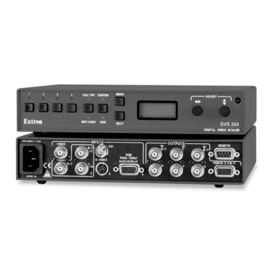
Page 14: Rear Panel Features
Installation and Operation Rear Panel Features The rear panels of the DVS 204 D and DVS 204 D 12V models, as shown below, contain all of the possible connectors available on the DVS 204 series of scalers (the DVS 204 and DVS 12V models do not come with an SDI input connector). - Page 15 SDI (serial digital interface) input connector — Connect an SDI signal to this female BNC connector. Only the DVS 204 D and DVS 204 D 12V models have an SDI connector. Video input 4: RGB pass-through, RGBS, or RGBcvS —...
- Page 16 (pin 5). To force one of the inputs to be always selected, leave the short to logic ground in place. The short overrides front panel input selections. DVS 204 • Installation and Operation...
-
Page 17: Front Panel Features
The front panel buttons, controls, LCD, and infrared sensor of the DVS 204, as shown below, are found on all models of the DVS 204 scaler series. The LEDs above each input button will light green and the LEDs above/below each picture control button will light amber when the button is pressed. -
Page 18: Menu Button
DVD player will defeat the advantage of having 3:2 pulldown detection in the DVS 204. All sizing adjustments to correct aspect ratio should be done using the DVS 204. To change the output aspect ratio of most DVD players, Enter the DVD player’s Setup or Action menu while the disc is stopped. -
Page 19: Menus, Configuration, And Adjustments
The default menus appear on the LCD when no adjustments are actively being made. They cycle between the screen showing the model of the scaler (DVS 204 or DVS 204 D) and the screen that shows the active input’s number and video format, as shown below. -
Page 20: Input Configuration
MENU MENU Main menus To return to the default screens, let the DVS 204 time-out for 10 seconds, or press the Menu button until the Exit Menu menu appears, then press the Next button. Submenus are accessed from a main menu by pressing the Next button. If you press the Menu button while a submenu is active, the next main menu will become active. -
Page 21: Input 2 Video Type
• H (default) – outputs horizontal sync through the "H" BNC • HV – outputs composite sync through the "H" BNC NOTE See the section "RGB pass-through" under the Rear Panel Features section of this chapter for further details. DVS 204 • Installation and Operation 2-11... -
Page 22: Resolution And Refresh Rates
It exactly matches the output rate of the DVS 204’s scaler to the frame rate of the active input. Select this feature if you will be using motion video sources with a display that is capable of a variety of refresh rates. -
Page 23: H Format
The following flowchart provides an overview of the Memory Preset submenus and the options for each setting. The presets will only save the Sizing and Centering information, but will not save information for the pass-through input, i.e., RGB at Input 4. DVS 204 • Installation and Operation 2-13... -
Page 24: Save (Save) Memory Preset
Next button. The presets will save the Sizing and Centering information in non-volatile memory, so powering down the DVS 204 will not lose the presets. Saving a preset by pressing the Next button will also advance to the next submenu (Clear memory preset). -
Page 25: Recalling A Preset
For CRT output, set the filter “Off”. Use either the Adjust horizontal ( ) or Adjust vertical ( ) knob to specify this mode as “On” or “Off”. The default is “On”. DVS 204 • Installation and Operation 2-15... -
Page 26: Blue Mode
( ) knob to specify this mode as “On” or “Off”. RGB delay (Triple-Action Switching) With Triple-Action Switching, the DVS 204 switches to the new sync signal before switching RGB (video) signals. RGB delay allows the display device to adjust to the new sync timing after a brief delay (during which the display is blanked) before displaying the new picture, which will appear without glitches. -
Page 27: Exit Menu
COL/TNT Tint 10 sec. timeout NOTE The Adjust horizontal knob and the Adjust vertical knob are used to adjust the image settings on the left and right sides of the LCD screen, respectively. DVS 204 • Installation and Operation 2-17... -
Page 28: Input Reset
LCD screen. System Reset The DVS 204 can be reset to all of its default values by holding down the Input 1 button while simultaneously plugging in the power cord. The System Reset message will be displayed on the LCD screen. -
Page 29: Front Panel Security Lockout (Executive Mode)
Front Panel Security Lockout (Executive Mode) To prevent accidental changes to settings, press the Col/Tnt and Center buttons simultaneously for 2 seconds to enable the DVS 204’s Executive mode. Executive mode locks all front panel functions. The menu system will still return to the Default menu when 10 seconds have elapsed. -
Page 30: Ir 901 Infrared Remote Control
Executive mode has been enabled on the DVS 204, input selection and adjustments can still be made from the IR 901. You must use the DVS 204’s front panel or the Windows-based control program (via an RS-232 device) to configure and program the scaler. See chapter three, “Serial Communication”, for details. -
Page 31: Troubleshooting
Troubleshooting This section gives recommendations on what to do if you have problems operating the DVS 204, and it provides examples and descriptions for some image problems you might encounter. The following are some tips to help you in troubleshooting. - Page 32 Installation and Operation, cont’d 2-22 DVS 204 • Installation and Operation...
-
Page 33: Chapter 3 • Serial Communication
DVS 204 Chapter Three Serial Communication RS-232 Programmer’s Guide Control Software for Windows... -
Page 34: Rs-232 Programmer's Guide
When the scaler receives a valid SIS command, it executes the command and sends a response to the host device. If the DVS 204 is unable to execute the command because the command is invalid or it contains invalid parameters, it returns an error response to the host. -
Page 35: Using The Command/Response Tables
7 = 1280x1024 ™ *NOTE: Lock or AFL is Accu-RATE Frame Lock 8 = 1360x765 9 = 1365x1024 10 = 480p 11 = 720p 12 = 1080p 13 = 1080i 14 = 1400x1050 15 = 576p DVS 204 • Serial Communication... -
Page 36: Command/Response Table For Sis Commands
Decrease the brightness. View the brightness value Show the brightness setting. Detail mode Set the detail level Specify the detail level. View the detail value Show the detail setting. Increment Increase detail level. Decrement Decrease detail level. DVS 204 • Serial Communication... - Page 37 Select a scaler output scan rate. View the output rate Show the scaler output rate. Video mute Mute on Mute video output. Example: Vmt1 Mute off Unmute video output. View video mute status Show the status of video mute. DVS 204 • Serial Communication...
- Page 38 •Pre •Sdi Zap (reset to default settings) Zap image adjustments/controls ZapI Reset the image adjustments to factory settings. Zap all DVS 204 settings/memories zXXX ZapXXX Reset everything: all settings and adjustments to the factory default. DVS 204 • Serial Communication...
-
Page 39: Command/Response Table For Special Function Sis Commands
RGB delay times RGB delay 0 = 0.0 seconds (default), 1 = 0.5 seconds, 2 = 1.0 seconds, ... in ½ second steps up to 10 = 5.0 seconds Example: 3*7# RGB07 Example: 3.5 second RGB delay DVS 204 • Serial Communication... -
Page 40: Control Software For Windows
Follow the instructions that appear on the screen. By default the installation creates a C:\DVS 204 directory, and it places two icons (DVS 204 Control Pgm and DVS 204 Help) into a group or folder named “Extron Electronics”. Using the control program Many items found in the DVS 204 Control Program are also accessible via front panel controls and the LCD menus described in chapter two. -
Page 41: Using The Help Program
Using the help program For information on program features, press the F1 computer key, or click on the Help menu from within the DVS 204 Control Program, or double-click on the DVS 204 Help icon in the Extron Electronics group or folder. - Page 42 Serial Communication, cont’d 3-10 DVS 204 • Serial Communication...
-
Page 43: Appendix A • Appendix
DVS 204 Appendix Appendix Specifications Part Numbers and Accessories Firmware Upgrade Installation Serial Digital Interface (SDI) Card Installation... -
Page 44: Specifications
Input type ........(RGBHV, RGBS, RGsB) pass-through, RGBS, RGBcvS Output type ........RGBHV, RGBS, RGsB Standards ........NTSC 3.58, NTSC 4.43, PAL, SECAM Input level ........0 V to 1.0 Vp-p Output level ........TTL: 5.0 Vp-p, unterminated Input impedance ......75 ohms DVS 204 • Appendix... - Page 45 All models ......Storage: -40 to +158 °F (-40 to +70 °C) / 10% to 90%, noncondensing DVS 204, DVS 204D ..Operating: +32 to +113 °F (0 to +45 °C) / 10% to 90%, noncondensing DVS 204/204D 12VDC ..Operating: +32 to +122 °F (0 to +50 °C) / 10% to 90%, noncondensing Rack mount ........
-
Page 46: Part Numbers And Accessories
Appendix, cont’d Part Numbers and Accessories Included parts These items are included in each order for a DVS 204 scaler: Included parts Part number DVS 204, 204 D, 204 12V, 204 D 12V (1) 60-442-01, -02, -11, -12 Rubber feet (self-adhesive) (4) -
Page 47: Firmware Upgrade Installation
Extron factory. Follow these steps to replace firmware in the scaler. Disconnect the AC or 12 VDC power cord from the DVS 204 to remove power from the unit. To prevent electric shock or damage, always unplug the DVS 204 scaler from the AC or DC power source before opening the enclosure. - Page 48 Gently, but firmly, press the chip into place in the socket. Replace the top cover on the DVS 204 scaler, and fasten it with the screws that were removed in step 3. Rack/furniture mount the scaler, and reconnect the AC or DC power cord.
-
Page 49: Serial Digital Interface (Sdi) Card Installation
Follow these steps to install an SDI card in the DVS 204. Disconnect the AC or DC power cord from the DVS 204 to remove power from the unit. To prevent electric shock, always unplug the DVS 204 scaler from the AC power source before opening the enclosure. - Page 50 Install the SDI connector’s hex nut and keep the SDI card from twisting as the nut is tightened. Replace the top cover on the DVS 204 scaler, and fasten it with the screws that were removed in step 3. Rack/furniture mount the scaler, and reconnect the AC power cord.
- Page 51 FCC Class A Notice Note: This equipment has been tested and found to comply with the limits for a Class A digital device, pursuant to part 15 of the FCC Rules. These limits are designed to provide reasonable protection against harmful interference when the equipment is operated in a commercial environment. This equipment generates, uses and can radiate radio frequency energy and, if not installed and used in accordance with the instruction manual, may cause harmful interference to radio communications.
- Page 52 Extron Electronics, USA Extron Electronics, Europe Extron Electronics, Asia Extron Electronics, Japan 1230 South Lewis Street Beeldschermweg 6C 135 Joo Seng Road, #04-01 Kyodo Building Anaheim, CA 92805 3821 AH Amersfoort PM Industrial Building 16 Ichibancho The Netherlands Singapore 368363 Chiyoda-ku, Tokyo 102-0082 Japan 714.491.1500 +31.33.453.4040...