
Related Manuals for Extron electronics CrossPoint Plus 84HV


Summary of Contents for Extron electronics CrossPoint Plus 84HV
- Page 1 CrossPoint Plus Matrix Switchers CrossPoint Plus 84, 88, 124, 128, 168, and 1616 HV and HVA 68-521-01 Rev. F 11 04...
- Page 2 Precautions Safety Instructions • English Warning This symbol is intended to alert the user of important operating and maintenance Power sources • This equipment should be operated only from the power source indicated on the product. This equipment is intended to be used with a main power system with a grounded (servicing) instructions in the literature provided with the equipment.
- Page 3 Quick Start — CrossPoint Plus Matrix Switchers Installation Step 1 Mount the switcher in a rack. Step 2 Sleeve Sleeve Turn off power to the input and output devices, Unbalanced Input and remove the power cords from them. (high impedance) Step 3 Ring Sleeve (s)
-
Page 4: Front Panel Controls
Quick Start — CrossPoint Plus Matrix Switchers, cont’d Front Panel Controls Input and output buttons and LEDs select and identify inputs and outputs. Input buttons also select presets. On HVA models, the output LEDs also display the audio level of the selected input. Enter button saves changes when you change the configuration. -
Page 5: Table Of Contents
Table of Contents Chapter 1 • Introduction ....................... 1-1 About the CrossPoint Plus Series Matrix Switchers .......... 1-2 Features ........................... 1-3 Chapter 2 • Installation ......................2-1 Rack Mounting the Switcher ..................2-2 Cabling and Rear Panel Views ..................2-2 Power connection ...................... - Page 6 Table of Contents, cont’d Worksheet example 2: Drawing ties ................3-19 Worksheet example 3: Test configuration ..............3-20 Matrix Switchers Configuration Worksheet ..............3-21 Chapter 4 • Programmer’s Guide ..................4-1 Host-to-Switcher Instructions ..................4-2 Switcher-Initiated Messages ..................4-2 Switcher Error Responses ....................
-
Page 7: Chapter 1 • Introduction
CrossPoint Plus Matrix Switchers Chapter One Introduction About the CrossPoint Plus Matrix Switchers Features... -
Page 8: About The Crosspoint Plus Series Matrix Switchers
Introduction Introduction, cont’d About the CrossPoint Plus Series Matrix Switchers The Extron CrossPoint Plus Series Matrix Switchers are ultra-wideband analog RGBHV matrix switchers that distribute any input to any combination of outputs. The matrix switchers can route multiple input/output configurations simultaneously. -
Page 9: Features
Monitor CrossPoint Plus 128HVA Projector /PAN SIZE BURS PHAS MIN/ LOCK ERIN FILT SIZE VSC 150 Projector Up to 8 Outputs RGB 109xi RGB 103xi RGB 112xi Sun/SGI Workstation PC Computer Macintosh Computer Up to 12 Inputs RGB 440 Laptop w/ Audio Outputs Document Camera REMO REMO... - Page 10 Introduction, cont’d CrossPoint Plus Series delivers the highest performance and the most cost- effective solution. Digital Sync Validation Processing (DSVP™) — In critical environments or unmanned, remote locations, it is vital to know that sources are active and switching. Extron’s exclusive DSVP confirms that input sources are active by scanning all sync inputs for active signals.
- Page 11 Operational flexibility — Operations such as input/output selection, setting of presets, and adjustment of audio levels can be performed on the front panel or over the RS-232/RS-422 link. The RS-232/RS-422 link allows remote control via a PC, RS-232 capable PDA, or control system. •...
- Page 12 Introduction, cont’d Switching flexibility — Individually buffered, independent matrix switched video outputs with audio follow and audio breakaway for HVA versions. • Any input to any or all outputs • Quick multiple tie — Multiple inputs can be switched to multiple outputs simultaneously.
-
Page 13: Chapter 2 • Installation
CrossPoint Plus Matrix Switchers Chapter Two Installation Rack Mounting the Switcher Cabling and Rear Panel Views... -
Page 14: Rack Mounting The Switcher
Installation Installation, cont’d Rack Mounting the Switcher The CrossPoint Plus 84, 88, 124, and 128 Matrix Switchers are housed in rack- mountable, 3U high, 19” wide metal enclosures. The CrossPoint Plus 168 and 1616 are in 6U high enclosures. The appropriate rack mount kit is included with each switcher. -
Page 15: Video Input And Output Connections
Video input and output connections All video input and output connections to the CrossPoint Plus switchers are made with female BNC connectors. Some types of video output devices do not have BNC video output connectors. For these cases, a suitable cable or connector adapter is necessary between the device output connector and the BNC input connector of the CrossPoint Plus. -
Page 16: Rs-232/422 Connection
Installation, cont’d Sleeve Tip (Left) Sleeve (Gnd) Ring (Right) Tip (Signal) Tip (Left) Sleeve (Gnd) Sleeve (Gnd) Unbalanced Mono Unbalanced Stereo Figure 2-4 — Phono audio connectors Connections for audio outputs — These 3.5 mm, 5-pole captive screw connectors output the selected unamplified, line level audio. Connect audio devices, such as an audio amplifier or powered speakers. -
Page 17: Additional Rear Panel Views
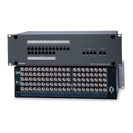
CrossPoint Plus 1616HVA, which is shown in figure 2-2. INPUTS 1 2 4 INPUTS 1 2 4 INPUTS OUTPUTS Figure 2-7 — Rear panel view, CrossPoint Plus 84HV INPUTS 1 2 4 INPUTS 1 2 4 INPUTS OUTPUTS Figure 2-8 — Rear panel view, CrossPoint Plus 84HVA... - Page 18 Installation, cont’d INPUTS 1 2 4 INPUTS 1 2 4 INPUTS OUTPUTS Figure 2-11 — Rear panel view, CrossPoint Plus 124HV INPUTS 1 2 4 INPUTS 1 2 4 INPUTS OUTPUTS Figure 2-12 — Rear panel view, CrossPoint Plus 124HVA INPUTS 1 2 4 INPUTS...
- Page 19 1 3 5 7 1 3 5 7 Figure 2-15 — Rear panel view, CrossPoint Plus 168HVA 1 3 5 7 1 3 5 7 Figure 2-16 — Rear panel view, CrossPoint Plus 1616HV CrossPoint Plus Matrix Switchers • Installation...
- Page 20 Installation, cont’d CrossPoint Plus Matrix Switchers • Installation...
-
Page 21: Chapter 3 • Operation
CrossPoint Plus Matrix Switchers Chapter Three Operation Front Panel Controls and Indicators Front Panel Operations Rear Panel Controls Worksheets... -
Page 22: Front Panel Controls And Indicators
Operation Operation, cont’d Front Panel Controls and Indicators The front panel controls (figure 3-1 and figure 3-2) are grouped into two sets. The input and output buttons and LED indicators are grouped on the left side of the control panel. The control buttons and input/output (I/O) selection buttons and indicators are grouped on the right side of the panel. -
Page 23: Input Buttons, Output Buttons, And Leds
Current configuration — The configuration that is currently being used (also called configuration 0). Global memory preset — A configuration that has been stored. Up to 16 global memory presets can be stored in memory. The input buttons select the desired preset memory location to load or retrieve a preset. When a preset is retrieved from memory, it becomes the current configuration. -
Page 24: I/O Controls
Operation, cont’d As a secondary function on HVA models, the Esc button increments the audio level of the selected input. In audio adjust mode, the Esc LED indicates a positive (+) gain value. A more detailed explanation of audio level adjustment is included in Viewing and adjusting the input audio level (HV A models only) on page 3-15. -
Page 25: Front Panel Operations
Front Panel Operations The following paragraphs detail the power-up process and then provide sample procedures for creating ties, sets of ties, and configurations; changing a configuration; viewing ties, sets of ties, and configurations; saving a preset; recalling a preset; and viewing and adjusting the audio level. Power On all models, power is automatically applied when the power cord is connected to an AC source. -
Page 26: Creating A Configuration
Operation, cont’d The I/O groups can be set up only by using the RS-232/422 port and either the SIS or the Windows control program. Ties between groups (an input in group 1 tied to an output in group 2) can be created under RS-232/422 control. Presets can also be created under RS-232/422 control that tie inputs and outputs across group boundaries. -
Page 27: Example 1: Create A Set Of Video And Audio Ties
If the input button for a grouped input is pressed, and then the output button for an output in a different group is pressed, the associated output LED blinks twice and goes out to indicate that output cannot be tied to the input. -
Page 28: Example 3: Remove A Tie From A Set Of Video And Audio Ties
Operation, cont’d LED key: = off, = on, = blinking, Press Press = flash once RGBHV INPUTS CONTROL ENTER PRESET VIEW RGBHV AUDIO OUTPUTS Press Press Press ENTER Figure 3-6 — Example 2: Adding a video tie Press and release the Enter button. The input and output LEDs turn off. The current configuration is now defined as video input 5 tied to video output 1, output 3, output 4, and output 8;... -
Page 29: Viewing A Configuration
LED key: = off, = on, = on for 2 seconds, then off INPUTS AUDIO CONTROL ENTER PRESET VIEW RGBHV AUDIO OUTPUTS Press Press ENTER Figure 3-8 — Example 3, step d: Removing an audio tie Press and release the Enter button. The input and output LEDs turn off. The current configuration is now defined as video input 5 tied to video output 1, output 3, output 4, and output 8;... -
Page 30: Example 4: View Video And Audio, Audio Only, And Video Only Ties
Operation, cont’d Example 4: View video and audio, audio-only, and video-only ties See figure 3-9, figure 3-10, figure 3-11, and figure 3-12 and the following steps for an example of viewing the video and audio, audio-only, and video-only ties in the current configuration. -
Page 31: Muting And Unmuting Video And/Or Audio
A set of ties can also be viewed by selecting a tied output. To demonstrate this, note the number of a lit output LED and press and release the output button for an unlit (untied) output LED. Observe that all of the untied outputs light. Then press the output button for the output LED noted previously and observe that the selected output LED, the tied input LED (input 5), and the output LEDs light for all of the outputs that are tied to the input. -
Page 32: Example 5: Muting And Unmuting An Output
Operation, cont’d One at a time, press and hold the output button(s) for the desired output(s) for approximately 2 seconds. The output LED(s) for the selected output(s) blink to indicate the mute or return to their previous state to indicate the unmute. -
Page 33: Using Presets
Press INPUTS VIEW CONTROL ENTER PRESET VIEW RGBHV AUDIO OUTPUTS Hold Hold LED key: = off, = on, = blinking, Hold Hold Figure 3-13 — Example 5, step d: Muting and unmuting outputs Using presets The current configuration (configuration 0) can be saved as a preset in any 1 of 16 preset memory addresses. -
Page 34: Example 6: Save A Preset
Operation, cont’d Example 6: Save a preset Refer to figure 3-14 and the following steps for an example of saving the current configuration as a preset. LED key: = off, = on, = blinking, = flash once INPUTS PRESET CONTROL ENTER PRESET VIEW RGBHV AUDIO... -
Page 35: Viewing And Adjusting The Input Audio Level (Hva Models Only)
Viewing and adjusting the input audio level (HVA models only) On HVA models, the audio level of each input can be displayed and adjusted through a range of -15dB to +9dB to ensure that there is no noticeable volume difference among sources. The audio level can be adjusted from the front panel or by using Extron’s Windows-based control program. - Page 36 Operation, cont’d Figure 3-16 and figure 3-17 show an audio level of +8dB displayed in the output LEDs on the two different CrossPoint Plus front panels. LED key: = off (value 0 dB), = blinking (value 1dB), = on (value 2dB), = flash once Press INPUTS...
-
Page 37: Executive Mode (Front Panel Security Lockout)
Press LED key: = off (value 0 dB), = blinking (value 1dB), = on (value 2dB) RGBHV AUDIO AUDIO INPUTS CONTROL ENTER PRESET VIEW RGBHV AUDIO OUTPUTS -1dB (9 times) VIEW Figure 3-18 — Example 8, step d: Adjusting the audio level, CrossPoint Plus 84, 88, 124, and 128 LED key: = off (value 0dB),... -
Page 38: System Reset To Factory Defaults
Operation, cont’d System reset to factory defaults To reset the switcher to the factory default settings, press and hold the Esc button on the front panel while AC power is being applied. Continue to hold the Esc button until the power up sequence is completed (all LEDs turn off, the Video and Audio LEDs turn on, the Esc LED blinks, and the Power LED (if equipped) turns on). -
Page 39: Plasma Display S-Video Problem
Plasma display S-video problem Extron has encountered a problem with the S-video output by some video conference codecs, when it is switched using a CrossPoint Plus. Some codecs change the DC offset on the chrominance (C) so that it is very different from the level on the luminance (Y). -
Page 40: Worksheet Example 2: Drawing Ties
Operation, cont’d Worksheet example 2: Drawing ties Figure 3-22 continues from worksheet example 1 by showing the video and audio ties that make up the configuration of preset 3, a solid ink line shows video ties, and a dashed pencil line shows the audio ties. In this example, the image of the presenter, from the main podium camera (input 1), is displayed in the main hall (output 1), to the overflow crowd in the conference room (output 4), and in the lobby (output 8). - Page 41 CrossPoint Plus Matrix Switchers • Operation 3-21...
- Page 42 Operation, cont’d 3-22 CrossPoint Plus Matrix Switchers • Operation...
-
Page 43: Chapter 4 • Programmer's Guide
CrossPoint Plus Matrix Switchers Chapter Four Programmer’s Guide Host-to-Switcher Instructions Switcher-Initiated Messages Switcher Error Responses Using the Command/Response Table Command/Response Table... -
Page 44: Host-To-Switcher Instructions
Programmer’s Guide Programmer’s Guide, cont’d The switcher’s rear panel RS-232/RS-422 connector (figure 4-1) can be connected to the serial port output of a host device such as a computer, RS-232 capable PDA, or control system. This connection makes software control of the switcher possible. RS-232 Function RS-422 Function —... -
Page 45: Switcher Error Responses
The switcher does not expect a response from the host, but, for example, the host program might request a new status. Switcher Error Responses When the switcher receives an SIS command and determines that it is valid, it performs the command and sends a response to the host device. If the switcher is unable to perform the command because the command is invalid or contains invalid parameters, the switcher returns an error response to the host. -
Page 46: Command/Response Table
Programmer’s Guide, cont’d Command/Response Table Symbol Definitions: = Carriage return/line feed = Carriage return (no line feed) • = space = Input number 01 – 08 (CrossPoint Plus 84, 88); Input and output numbers in 01 – 12 (CrossPoint Plus 124, 128); commands may be entered as either 1-digit or 2-digit 01 –... - Page 47 Command/response table for SIS commands (Cont’d) Command ASCII Command Response Additional description (host to switcher) (switcher to host) List all sync (DSVP) Input•Horz.•Vert. •• • thru •• • Example: Input•Horz.•Vert. 01••031.50•060.00 Input 1 (H) 31.5 kHz (V) 60 Hz thru thru 16••031.50•060.00 Input 16 (H) 31.5 kHz (V) 60 Hz.
- Page 48 Programmer’s Guide, cont’d Command/response table for SIS commands (Cont’d) Command ASCII Command Response Additional description (host to switcher) (switcher to host) Start direct write of global presets Write Preset Ready Allows direct entry of presets. {Tie commands} {Define ties for preset.} End direct write of global presets End Write Preset Saves directly written presets.
- Page 49 Command/response table for SIS commands (Cont’d) Command ASCII Command Response Additional description (host to switcher) (switcher to host) Reset all mutes ZapZ Unmute all outputs. Reset whole switcher zXXX ZapXXX Clears all ties and global presets, the RGB delay, the I/O grouping, and resets all audio gains to 0dB.
- Page 50 Programmer’s Guide, cont’d CrossPoint Plus Matrix Switchers • Programmer’s Guide...
-
Page 51: Chapter 5 • Matrix Software
CrossPoint Plus Matrix Switchers Chapter Five Matrix Software Matrix Switchers Control Program Button-Label Generator... -
Page 52: Matrix Switchers Control Program
Matrix Software Matrix Software, cont’d Two software programs accompany the CrossPoint Plus Series switchers: • The Extron Matrix Switcher+ Control Program (Extron part #29-015-01), which communicates with the switcher via the RS-232/RS-422 port, provides an easy way for you to set up ties and sets of ties. If your CrossPoint Plus Series switcher was previously set up for RS-232, and your computer comm port uses RS-422, you must change the switcher cabling to match the computer interface. -
Page 53: Windows Buttons
Figure 5-1 — Extron Matrix Switcher+ Control Program window (blank) Figure 5-2 — Sample program window (complete) To make the control program easier to use, assign a device icon to each input and output. Click on a box that represents an input or output, and drag the desired icon onto the box from the icon palette that appears. -
Page 54: Windows Menus
Matrix Software, cont’d Executive mode — Allows you to lock out front panel operations, except for the view-only mode functions. Presets menu — Displays a list of up to 16 presets. You can select a preset from the list to display it in the window. Go —... -
Page 55: Using Emulation Mode
Audio-config — Displays the audio gain level settings for each input and allows you to change them. Preferences menu — Immediate changes — Causes changes to take effect immediately. Hold/verify changes — Delays implementation of changes until the Changes – Take button is pressed. Ties as lines —... -
Page 56: Using The Software
Matrix Software, cont’d Using the software To run the Button-Label Generator program, double-click on the Button-Label Generator icon (shown at left) in the Extron Electronics group or folder, and click OK when prompted. The Extron’s Button-Label Generator window appears (figure 5-3). Under System selection, choose Mtrx50/MAV/XPoint. -
Page 57: Appendix A • Specifications
CrossPoint Plus Matrix Switchers A ppendix A Specifications Specifications Part Numbers... - Page 58 Specifications Specifications, cont’d Video Routing .......... 84 Series ....8 x 4 matrix 88 Series ....8 x 8 matrix 124 Series ....12 x 4 matrix 128 Series ....12 x 8 matrix 168 Series ....16 x 8 matrix 1616 Series ....
- Page 59 Output impedance ...... 75 ohms Polarity .......... Positive or negative (follows input) Audio — audio models only Routing .......... 84 Series ....8 x 4 stereo matrix 88 Series ....8 x 8 stereo matrix 124 Series ....12 x 4 stereo matrix 128 Series ....
-
Page 60: Crosspoint Plus Part Numbers
MTBF ..........30,000 hours Warranty ........3 years parts and labor Specifications are subject to change without notice. Part Numbers CrossPoint Plus part numbers Extron Part Part # CrossPoint Plus 84HV 60-337-02 CrossPoint Plus 84HVA 60-337-01 CrossPoint Plus 88HV 60-336-02 CrossPoint Plus 88HVA... -
Page 61: Optional Accessories
Optional accessories Extron Part Part # Rack/desk mounting kit 70-077-03 MKP 1000 Gray 60-239-01 Black 60-239-02 White 60-239-03 MCP 1000M (master) 60-298-01 MCP 1000S (slave) 60-298-02 Captive screw audio connector 10-319-10 RCA-to-BNC adapter 10-264-01 SVHS - BNC adapter 26-353-01 Cables When using signals with a scanning frequency of 15-125 kHz and running distances of 100 feet or more, use high resolution BNC cables to achieve maximum performance. - Page 62 Specifications, cont’d Pre-cut cables BNC-4 Mini HR cable is used for RGBS cable runs, and BNC-5 Mini HR cable is used for RGBHV cable runs. Either type can also be used for composite video, S-video, or RGsB. All Extron BNC cables have male connectors on both ends. A plenum version of the BNC-5 Mini HR cable is also available.
-
Page 63: Appendix B • Reference Information
CrossPoint Plus Matrix Switchers A ppendix B Reference Information Hardware Upgrades Button Labels... -
Page 64: Hardware Upgrades
Reference Information Reference Information, cont’d Hardware Upgrades This appendix contains procedures for performing hardware maintenance procedures such as swapping the RS-232 and RS-422 ports, installing a new firmware update, and replacing the fuse. Opening the switcher Before you can perform any of the hardware upgrade procedures, you must open the switcher. -
Page 65: Opening The Crosspoint Plus 168 And 1616
If you are updating the firmware, remove the two screws at the front edge of the bottom cover, press the two receptacle tabs on the top Ribbon cable cable outward as shown at the left, and pull back gently on Connector the cable connector to remove it from the receptacle. -
Page 66: Closing The Switcher
Reference Information, cont’d Closing the switcher Reinstall any cables removed. To plug a self latching cable into the desired receptacle, align the holes in the connector with the pins in the Ribbon cable receptacle, and press evenly until the receptacle tabs lock into place. -
Page 67: Installing A Firmware Update
Attach the power cord to the switcher and to the AC power source. Ensure the switcher is working properly. If the switcher was removed from a rack, remove its power cord, reattach the switcher to the rack, and reconnect the power cord. Reconnect the input and output cables. -
Page 68: Replacing The Ac Fuse (Crosspoint Plus 84, 88, 124, And 128 Only
Reference Information, cont’d Reinstall the switcher’s front panel and cover. See Closing the switcher on page B-4. If you choose to check for proper operation before putting the cover back on, ensure that tools and hands are outside the switcher and then perform step 11. - Page 69 CrossPoint Plus Matrix Switchers • Reference Information...
- Page 70 Reference Information, cont’d CrossPoint Plus Matrix Switchers • Reference Information...
- Page 71 FCC Class A Notice Note: This equipment has been tested and found to comply with the limits for a Class A digital device, pursuant to part 15 of the FCC Rules. These limits are designed to provide reasonable protection against harmful interference when the equipment is operated in a commercial environment.
- Page 72 Extron Electronics, USA Extron Electronics, Europe Extron Electronics, Asia Extron Electronics, Japan 1230 South Lewis Street Beeldschermweg 6C 135 Joo Seng Road, #04-01 Daisan DMJ Building 6F Anaheim, CA 92805 3821 AH Amersfoort PM Industrial Building 3-9-1 Kudan Minami The Netherlands Singapore 368363 Chiyoda-ku, Tokyo 102-0074 Japan 714.491.1500...