
Related Manuals for Directed Electronics AutoCommand 20095


Summary of Contents for Directed Electronics AutoCommand 20095
- Page 1 M M o o d d e e l l 2 2 0 0 0 0 9 9 5 5 ➤ O O w w n n e e r r ’ ’ s s G G u u i i d d e e...
-
Page 2: L L I I M M I I T T E E D D L L I I F F E E T T I I M M E E C C O O N N S S U U M M E E R R W W A A R R R R A A N N T T Y Y
Directed Electronics (hereinafter "Directed") promises to the original purchaser to repair or replace with a comparable reconditioned Directed DIY unit if this Directed DIY unit (hereinafter "Unit"), excluding without limitation, any remote transmitters or associated... - Page 3 This product warranty is automatically void if its date code or serial number is defaced, missing, or altered. This warranty will not be valid unless you have completed the war- ranty card and mailed it to Directed Electronics. within 10 days after purchase to the address listed on the warranty registration card.
-
Page 4: Table Of Contents
........38 © 2005 directed electronics—all rights reser ved... - Page 5 ......................5 5 1 1 © 2005 directed electronics—all rights reser ved...
-
Page 6: Lcd 2-Way Configuration
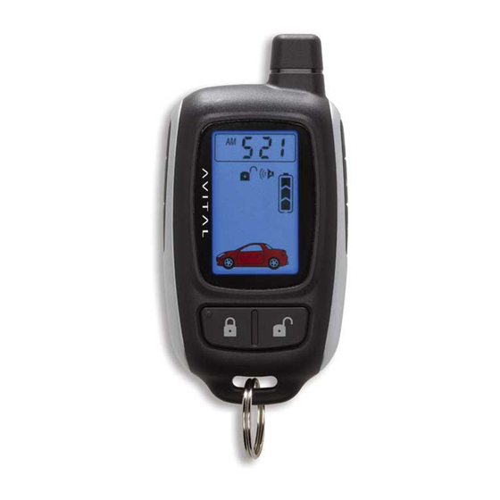
➜ LCD 2-way configuration © 2005 directed electronics—all rights reser ved... - Page 7 Remote Start Button Valet Mode Indicator Remote Start Safety Shutdown Indicator Battery Level Indicator Auxiliary Button Temperature-Controlled Remote Start Indicator Silent Arm/Disarm Mode Indicator Full Trigger Alert Indicator Arm/Disarm Indicator Function Button Celsius/Fahrenheit Indicator © 2005 directed electronics—all rights reser ved...
-
Page 8: Standard 4-Button Configuration
T T u u r r b b o o / / S S h h o o r r t t R R u u n n . pressed together control channel 4 4 output. pressed together control channel 5 5 output. pressed together display interior car temperature. © 2005 directed electronics—all rights reser ved... - Page 9 By carefully reading this Owner's Guide prior to using your system, you will maximize the use of this system and its features. You can print additional or replacement copies of this manual by accessing our web site at www.directed.com. © 2005 directed electronics—all rights reser ved...
-
Page 10: System Maintenance
Your remote is powered by a small, lightweight 3-volt lithium battery (CR2032) that will last approximately one year under normal use. When the battery begins to weaken, operating range will be reduced and the LED on the remote will dim. © 2005 directed electronics—all rights reser ved... -
Page 11: Your Warranty
(2) This device must accept any interference received, including interference that may cause undesirable operation. Directed Electronics, Inc. 544 Series Tested to Comply with FCC Standards Directed Electronics, Inc. 477T Series Tested to Comply with FCC Standards © 2005 directed electronics—all rights reser ved... -
Page 12: Caution
➜ caution This product is designed for fuel injected, automatic transmission vehicles only. Use of this product in a standard transmission vehicle is dangerous and contrary the product's intended use. © 2005 directed electronics—all rights reser ved... -
Page 13: Lcd 2-Way Remote Standard Configuration
For more information, please refer to the Function Button Configurations section of this guide. © 2005 directed electronics—all rights reser ved... - Page 14 Disarming the system while in temperature auto start mode will cause the system to exit this mode. Buttons The numeric display toggles between the time of the day and the alarm clock when these buttons are pressed simultaneously. © 2005 directed electronics—all rights reser ved...
-
Page 15: Standard Lcd 2-Way Icon Configuration
The numeric display icon will show the hours and minutes. Icon The AM/PM icon indicates the time before or after noon. Icon The alarm clock mode icon indicates that the alarm clock mode is active. © 2005 directed electronics—all rights reser ved... - Page 16 24 hours from the time activated. Icon The VRS mode icon has no function. Icon The vehicle page mode icon displays when the alarm module is paging the transceiver. © 2005 directed electronics—all rights reser ved...
- Page 17 The Valet mode icon appears when the system is in Valet mode. Icon The remote start safety shut down icon indicates the vehicle may be in gear or other unsafe condition inhibiting remote start operation. © 2005 directed electronics—all rights reser ved...
- Page 18 The arm icon appears when the vehicle is armed and locked. The disarm icon appears when the vehicle is disarmed and unlocked. Icon Celsius/Fahrenheit icon indicates the current mode of the displayed temperature either in Celsius or Fahrenheit. © 2005 directed electronics—all rights reser ved...
- Page 19 6 Times*** Adjust Mode (hour)** Timer Count Down 7 Times*** Adjust Mode (min)** Timer Count 8 Times*** 5 Selections Down Ending Melody 1/2/3/4/5 Selection 1** RS Timer Count 9 Times*** Down Mode (on/off )* © 2005 directed electronics—all rights reser ved...
- Page 20 **** Press once to have the alarm clock on. Press twice to have the alarm clock off. The remote will revert to normal operation from the set mode when 15-seconds has elapsed without a button entry. © 2005 directed electronics—all rights reser ved...
-
Page 21: 4-Button Remote Standard Configuration
The remote start function of your system is controlled by pressing this button. Buttons An optional auxiliary convenience or expansion function that you have added to your system can be activated by pressing these buttons simultaneously. The auxiliary output controls __________________________. © 2005 directed electronics—all rights reser ved... -
Page 22: L L C C D D 2 2 - - W W A A Y Y R R E E M M O O T T E E O O P P E E R R A A T T I I O O N
When the transceiver receives a page it will generate a page notifi- cation to the user (notifications are audible beeps or the remote vibrates) and the LCD icons will display the current system status. © 2005 directed electronics—all rights reser ved... -
Page 23: Warning! Safety First
Therefore, never operate the system in an enclosed area or partially enclosed area without ventilation (such as a garage). When parking in an enclosed or partially enclosed area or when having the © 2005 directed electronics—all rights reser ved... - Page 24 Directed dealer to fix the problem. ➤ After the remote start module has been installed, contact your authorized dealer to have him or her test the remote start module by performing the Safety Check outlined in the © 2005 directed electronics—all rights reser ved...
-
Page 25: Active Arming
LED will flash approximately once per second, indicating that the system is actively protecting your vehicle. If you hear a second chirp after arming and note that the © 2005 directed electronics—all rights reser ved... -
Page 26: Passive Arming
Heavy impacts trip a Triggered Sequence. The sequence consists of the siren sounding continuously and the parking lights flashing for a pre-programmed period, which can range in duration from 1 to 180 seconds. © 2005 directed electronics—all rights reser ved... -
Page 27: Warn Away Response Description
The transceiver will enter Page Recognition Mode and operate alarm page alerts. note: Icons 13 and 14 represent alarm system zone inputs. For more information about icons and the zones they represent refer to the Standard Remote Configurations section. © 2005 directed electronics—all rights reser ved... -
Page 28: Triggered Response Description
Zone 5. When a Triggered Response is activated the transceiver will: ➤ Repeat four quick beeps (or vibrate) for 15 seconds. ➤ The full trigger alert icon (28) will turn on for 15 seconds. © 2005 directed electronics—all rights reser ved... -
Page 29: Multi-Level Security Arming
Zone 4 is now bypassed. ➤ Press a fourth time within five seconds: The siren chirps four times followed by a long chirp. Zones 2 and 4 are now bypassed. © 2005 directed electronics—all rights reser ved... -
Page 30: Arming While Driving
® response page while armed, the first press of the unlock button will clear the page alert. A second press will turn the siren off, and a third press will disarm the system. © 2005 directed electronics—all rights reser ved... -
Page 31: Disarming
This prevents you from disabling the system should you wish to disarm it without visually checking the vehicle. Pressing after resetting the system will disarm the system; pressing this button during the first six © 2005 directed electronics—all rights reser ved... -
Page 32: Disarming Without A Remote
Number of Presses_____________________________________ important! The Valet button can be programmed to respond to 1-5 presses for the disarm function. You must check with the installer to verify the programming for your individual unit. © 2005 directed electronics—all rights reser ved... -
Page 33: Silent Mode
The LCD 2-way remote will beep (or vibrate) continuously when the system enters panic mode. The 2-way remote will not generate a page notification when panic mode is exited. © 2005 directed electronics—all rights reser ved... -
Page 34: Valet Mode
1. Open any vehicle door. 2. Press 3. Press 4. Press again. The status LED will light solidly if you are entering Valet Mode, and it will go out if you are exiting Valet Mode. © 2005 directed electronics—all rights reser ved... -
Page 35: Remote Start
4. In gasoline vehicles, the engine will start 4 seconds after the parking lights flash. In diesel vehicles, the engine will start when the WAIT-TO-START indicator on the vehicle's dash goes out. © 2005 directed electronics—all rights reser ved... - Page 36 The shutdown toggle switch is put into the OFF position. ➤ The pre-programmed run time (12, 24, or 60 minutes) has elapsed. ➤ Remote button is pressed twice within 3 seconds. The LCD 2-way remote will generate a page notification with a © 2005 directed electronics—all rights reser ved...
-
Page 37: Valet Take-Over
3. The engine will run until the pre-programmed time elapses or a shut-down input is received. (See the previous Remote Start section for a complete list of shut-down inputs.) note: This feature will not work if the brake pedal is being pressed. © 2005 directed electronics—all rights reser ved... -
Page 38: Short-Run/Turbo
Immediately press to advance the hour selection or reverse the hour selection. Once the correct hour is displayed press again and the minute selection will start flashing. © 2005 directed electronics—all rights reser ved... -
Page 39: Temperature Check Mode
Press Timer mode buttons. The vehicle will confirm with 4 parking light flashes. A 1-second delay will start. © 2005 directed electronics—all rights reser ved... -
Page 40: Starter Anti-Grind Circuitry
This prevents damage to the starter motor if the key is turned to the start position during remote start operation. © 2005 directed electronics—all rights reser ved... -
Page 41: Disabling The Remote Start System
The two most important are hood and brake inputs. The hood input will prevent the motor from starting, as well as shut it down, any time the hood is opened. The brake © 2005 directed electronics—all rights reser ved... -
Page 42: Nuisance Prevention Circuitry
The vehicle doors are protected by NPC differently. If your secu- rity system is triggered by an open door for three full cycles, the system will bypass the doors until the trigger ceases. © 2005 directed electronics—all rights reser ved... - Page 43 The microprocessor will also record and report any triggers that occurred during your absence. Refer to the System Status Chirps and Table of Zones sections of this guide for diagnostic information. © 2005 directed electronics—all rights reser ved...
-
Page 44: Arming Diagnostics
(see Table of Zones section). The secu- rity system will retain this information in its memory and chirp four or five times each time it is disarmed, until the next time that the ignition is turned on. © 2005 directed electronics—all rights reser ved... -
Page 45: System Status Chirps
A zone is represented by the number of LED flashes used by the system to identify a particular type of input. Standard input assignments are listed in the following table, along with spaces to write in any optional sensors or switches that have been installed. © 2005 directed electronics—all rights reser ved... -
Page 46: Interpreting Zone Diagnostics
If your system has been triggered but the LED has been reset by turning on the ignition, your dealer can still recall the last two zones that were triggered. Contact your dealer for details. © 2005 directed electronics—all rights reser ved... - Page 47 Your system transmits and receives at 434 MHz. This provides a cleaner spectrum with less interference and a more stable signal. Enjoy a phenomenal increase in range, even in areas with high radio interference. © 2005 directed electronics—all rights reser ved...
- Page 48 Valet Mode and the battery is disconnected for any reason, such as servicing the car, when the battery is reconnected the unit will still be in Valet Mode. This applies to all states of the system including arm, disarm, and Valet Mode. © 2005 directed electronics—all rights reser ved...
- Page 49 A A c c t t i i v v e e arming (from remote only) or passive arming (auto- matic arming 30 seconds after the last door has been closed). ➤ Arming/disarming siren chirps o o n n or off. © 2005 directed electronics—all rights reser ved...
- Page 50 When the system passively arms after one hour, the entry point that has been left open, and anything con- nected to the same zone, is bypassed and cannot trigger the system. However, the remaining inputs to the system are fully operational. © 2005 directed electronics—all rights reser ved...
- Page 51 6 6 d d e e c c i i b b e e l l s s q q u u i i e e t t e e r r than the full alarm blast. © 2005 directed electronics—all rights reser ved...
- Page 52 An invisible dome of coverage is estab- Field Disturbance Sensor: lished by installing the 508D “radar” sensor. Your system can © 2005 directed electronics—all rights reser ved...
- Page 53 This system is compatible with Directed Video’s Mobile Video: MCB1000 Multi-Channel Controller, featuring on-screen secu- rity system programming and zone trigger information. © 2005 directed electronics—all rights reser ved...
- Page 54 A hand-held, transceiver which operates and LCD 2-Way Remote: monitors the various functions of your system. © 2005 directed electronics—all rights reser ved...
- Page 55 A zone is a separate input that the alarm can recognize as Zone: unique. Each input to the system is connected to a particular zone. Often two or more inputs may share the same zone. © 2005 directed electronics—all rights reser ved...
- Page 56 To disable the remote start system ■ To disable the remote start, move the shutdown toggle switch to the OFF position. Location of Valet switch_________________________________ Number of Valet switch pulses for disarming_______________ © 2005 directed electronics—all rights reser ved...
- Page 57 The company behind this system is Directed Electronics. Since its inception, Directed Electronics has had one purpose, to provide consumers with the finest vehicle security and car stereo products and accessories available. The recipient of nearly 100 patents and Innovations Awards in the field of advanced electronic technology, Directed is ISO 9001 registered.