
Related Manuals for Planet GSW-1600S


Summary of Contents for Planet GSW-1600S
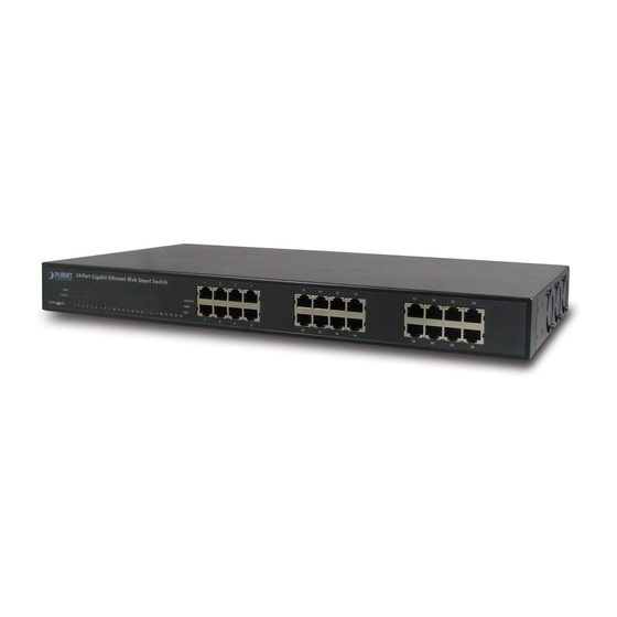
- Page 1 10/100/1000Mbps 16/24-port Web Smart Gigabit Ethernet Switch GSW-1600S/GSW-2400S User’s Manual...
-
Page 2: Fcc Warning
PLANET has made every effort to ensure that this User ’s Manual is accurate; PLANET disclaims liability for any inaccuracies or omissions that may have occurred. -
Page 3: Table Of Contents
2. INSTALLATION ..........................3 2.1 P ...............................3 RODUCT ESCRIPTION 2.1.1 Product Overview...............................3 2.1.2 GSW-1600S/2400S Front Panel........................3 2.1.3 LED Indicators ..............................3 2.1.4 GSW-1600S/2400S Rear Panel ........................4 2.2 I GSW-1600S/2400S ..........................4 NSTALLING A 2.2.1 Desktop Installation ............................4 2.2.2 Rack Mounting ..............................5 3. CONFIGURATION........................7 3.1 P ...........................7... -
Page 4: Introduction
It contains specifications of GSW-1600S/2400S. § Appendices It contains cable information of GSW-1600S/2400S. In the following section, terms “Switch” with upper case means the two switches, i.e. GSW-1600S or GSW-2400S. Terms with lower case “switch” means any Ethernet switches. 1.3 Product Features §... -
Page 5: Product Specifications
§ Support CSMA/CD protocol § 100~240VAC, 50~60Hz universal Power input § FCC, CE class A compliant 1.4 Product Specifications Model GSW-1600S GSW-2400S Hardware Specification Network ports Switch architecture Store-and-Forward Switch Fabric 32Gbps 48Gbps Switch throughput 23.8Mpps 35.7Mpps Address Table 8K entries... -
Page 6: Installation
Basic knowledge of networking is assumed. Please read this chapter completely before continuing. 2.1 Product Description The PLANET GSW-1600S/GSW-2400S is a 16/24-port 10/100/1000 Mbps Web Smart with non-blocking wire-speed performance Ethernet Switch. With 32/48Gbps internal switching fabric, the Switch can handle extremely large amounts of data transmission in a secure topology linking to a backbone or high-power servers. -
Page 7: Gsw-1600S/2400S Rear Panel
This section describes how to install your GSW-1600S/2400S Web Smart Gigabit Ethernet Switch and make connections to the Switch. Please read the following topics and perform the procedures in the order being presented. PLANET Web Smart Gigabit Ethernet Switch do not need software configuration. To install the Switch on a desktop or shelf, simply complete the following steps. -
Page 8: Rack Mounting
B. Connect the power plug of the power cable to a standard wall outlet. When the Switch receives power, the Power LED should remain solid Green. 2.2.2 Rack Mounting To install the switch in a 19-inch standard rack, follow the instructions described below. Step1: Place your Switch on a hard flat surface, with the front panel positioned towards your front side. -
Page 10: Configuration
3. CONFIGURATION Unlike the unmanaged switch (Dumb switch), the Switch performs series smart functions that make the Switch operate more effectively. This Chapter describes the common usage of the Switch ’s Smart Configuration. 3.1 Preparing for configuration When you are ready to configure the smart functions of the Web Smart Gigabit Ethernet Switch, please install the Web Switch utility and it can easily list the Switch in your Ethernet environment. - Page 11 Figure 3-2 Web Switch Utility installation wizard Press on “Next” button to install the Web Switch Utility to the default installation folder. Figure 3-3 Web Switch Utility installation process...
- Page 12 Figure 3-4 Web Switch Utility installation process Figure 3-5 Web Switch Utility installation process...
- Page 13 Figure 3-7 Web Switch Utility installation completed 3. After complete the installation, run “Web Switch Utility.exe” in default installation folder “C:\Program Files\Web Switch Utility” or run start -> Program Files -> PLANET Web Switch -> Web Switch Utility to start the management program.
- Page 14 The PLANET Web Switch Utility window then pops up as shown in Figure 3-8. Figure 3-8 The Web Switch Utility application window There are four main ports of the Web Switch Utility application, they are Toolbar, Discovery List, Monitor List, and Device Setting, please refer to the below section for details.
- Page 15 Figure 3-9 File function category on Web Switch Utility 3.1.1.1.2 View The “View” function category provides view log and clear log functions, these functions will help user to view and clear the trap messages. The detail explanation of each item is shown as below: View Log: to display the events of the Switch.
- Page 16 3.1.1.1.4 Help In the “Help” function category, it provides “About” function, it display the version of the Web Switch Utility. Figure 3-12 Help message on Web Switch Utility’s 3.1.1.2 Discovery List This function allows user to list the Switch in the entire network. By pressing the “Discovery” button, you can list all the Switch in the discovery list.
- Page 17 The Discovery List contains nine titles: MAC Address: display the Switch MAC Address. IP Address: display the current IP address of the Switch. Protocol version: display the version of the Utility protocol. Product Name: display the Switch model name. System Name: display the appointed Switch system name. Location: display where the Switch is located.
- Page 18 MAC Address: display the Switch MAC Address. Protocol version: display the version of the Utility protocol. Product Name: display the Switch model name. System Name: display the appointed Switch system name. Location: display where the Switch is located. Trap IP: display the IP address where the Trap to be sent. Subnet Mask: display the Subnet Mask configuration of the Switch.
- Page 19 Figure 3-16 Trap information In order to receive Trap information, the Trap IP and Trap Events must be configured in the GSW Note -1600S /2400S Web management interface. Please refer to chapter 3.1.2.10 Trap for detail information. Add Item: To add a device to the Monitor List manually, enter the IP Address of the device that want to monitor. Delete Item: To delete the device from the Monitor List.
-
Page 20: Configure The Gsw-1600S/2400S
GSW-1600S /2400S can be configured through the Web Browser. A network administrator can manage and monitor the GSW-1600S /2400S from the local LAN. This section indicates how to configure the Switch to enable its smart function. The smart functions are shown as below: ◆... - Page 21 Figure 3-20 Login page 3.1.2.2 Main Menu After entering the password, the main screen appears, the main screen displays the Switch status. The screen in Figure 3-21 appears. Figure 3-21 The Main page 3.1.2.3 Port This function allows displaying each port ’s status. The Link Status in the screen displays the current connection speed and duplex mode;...
- Page 22 Figure 3-22 The Port Setting page Press the port ID to configure each port ’s speed, flow control, QoS priority and link status. The screen in Figure 3-23 appears. Figure 3-23 The Per Port Setting page The options and descriptions of Port Settings show as below: Speed: this function provides six modes —100M Full, 100M Half, 10M Full, 10M Half, Auto and Disable Flow Control: this setting determines whether or not the Switch will be handling flow control.
- Page 23 “Apply” button to take effect. Once you want to modify the existence VLAN Group, press the ID parameter, the ID VLAN configuration screen will pop out. The screen in Figure 3-25 appears. The GSW-1600S supports 16-port Based-VLAN groups and the GSW-2400S supports 24-port Based-VLAN groups...
- Page 24 There are three selections in each trunk group setting as follow: Group 1: Selection 1(Disable) Selection 2(port 1, 2) Selection 3(port 1, 2, 3, 4) (GSW-1600S/2400S) Group 2: Selection 1(Disable), Selection 2(port5, 6), Selection 3(port 5, 6, 7, 8) (GSW-1600S/2400S)
- Page 25 Figure 3-27 Mirror Setting page 3.1.2.7 Status Click on the “Status” to present the Switch status on this screen, it display the Switch Status, Port Status, VLAN Status, Trunk Status and Mirror Status. Press “Refresh” to renew the posted information. The Status screen in Figure 3-28 appears.
- Page 26 Figure 3-29 Statistics page Press the port ID for detail packet information on each port. The screen in Figure 3-30 appears. Figure 3-30 Per port Statistics page 3.1.2.9 System The System Setting includes the System name, Location name, Login Timeout, IP Address, Subnet Mask and Gateway. Through the Web Switch Utility, you can easily recognize the device by using the System Name and the Location Name.
- Page 27 Figure 3-31 System Setting page 3.1.2.10 Trap The Trap function enables the Switch to monitor the Trap through the Web Switch Utility, set the Trap IP Address of the manager workstation where the trap to be sent. The screen in Figure 3-32 appears Figure 3-32 Trap Setting page The description of each item is shown as below: Events: Monitoring the Switch’s trap.
- Page 28 3.1.2.12 Backup Setting This function allows backup the current configuration of GSW-1600S /2400S. The screen in Figure 3-34 appears. Figure 3-34 Backup Setting page Press the “Backup” button to save the current configuration in manager workstation. The following screens in Figure 3-35...
- Page 29 Figure 3-35 Backup Setting dialog box Figure 3-36 Backup Setting dialog box Figure 3-37 Backup Setting message box...
- Page 30 To restore a configuration file to the Switch, please specify the backup file and press the “Restore” button to continue, after restore completed, the Switch will reboot for the previous configuration. The screen in Figure 3-38 & 3-39 appears. Figure 3-38 Restore Setting page Figure 3-39 Restore Setting page 3.1.2.13 Reset Setting The Factory Reset button can reset the Switch back to the factory default settings.
- Page 31 Figure 3-40 Reset Setting page 3.1.2.14 Logout Click on this link; the web management interface logout immediately and login page appears. Figure 3-41 Login page appears after click on the Logout link...
-
Page 32: Switch Operation
4. SWITCH OPERATION 4.1 Address Table The Switch is implemented with an address table. This address table composed of many entries. Each entry is used to store the address information of some node in network, including MAC address, port no, etc. This information comes from the learning process of Ethernet Switch. -
Page 33: Switch ' Srj-45 Pin Assignments
APPENDIX A A.1 Switch‘s RJ-45 Pin Assignments 1000Mbps, 1000Base T Contact MDI-X BI_DA+ BI_DB+ BI_DA- BI_DB- BI_DB+ BI_DA+ BI_DC+ BI_DD+ BI_DC- BI_DD- BI_DB- BI_DA- BI_DD+ BI_DC+ BI_DD- BI_DC- Implicit implementation of the crossover function within a twisted-pair cable, or at a wiring panel, while not expressly forbidden, is beyond the scope of this standard.