
Related Manuals for Planet GSW-2400HPS


Summary of Contents for Planet GSW-2400HPS
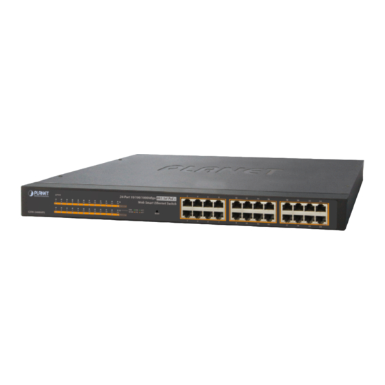
- Page 1 User’s Manual 24-Port Gigabit 802.3at PoE Web Smart Ethernet Switch GSW-2400HPS www.PLANET.com.tw...
-
Page 2: Fcc Warning
PLANET is a registered trademark of PLANET Technology Corp. All other trademarks belong to their respective owners. Disclaimer PLANET Technology does not warrant that the hardware will work properly in all environments and applications, and makes no warranty and representation, either implied or expressed, with respect to the quality, performance, merchantability, or fitness for a particular purpose. -
Page 3: Table Of Contents
User’s Manual of GSW-2400HPS TABLE OF CONTENTS 1. INTRODUCTION........................6 1.1 Packet Contents ............................6 1.2 Product Description .............................7 1.3 How to Use This Manual ..........................9 1.4 Product Features............................9 1.5 Product Specifications ..........................11 2. INSTALLATION ........................13 2.1 Hardware Description ..........................13 2.1.1 Switch Front Panel ..............................13... - Page 4 User’s Manual of GSW-2400HPS 4.3.2.3 VLAN Setting Example: ..........................41 4.3.3 QoS ..................................46 4.3.3.1 Port-based Priority Setting.........................47 4.3.3.2 Packet Scheduling.............................48 4.3.4 Trunk..................................50 4.3.4.1 Trunk Group ..............................51 4.3.5 Port Mirroring...............................53 4.3.6 Port Isolation................................56 4.3.7 Bandwidth Control ...............................58 4.3.8 Jumbo Frame ..............................60 4.3.9 Loop Protection ..............................61 4.3.10 Green Networking..............................62...
- Page 5 User’s Manual of GSW-2400HPS 5.5 Auto-Negotiation ............................83 6. POWER OVER ETHERNET OVERVIEW ................84 7. TROUBLESHOOTING......................87 APPENDEX A .......................... 89 A.1 Switch's RJ-45 Pin Assignments 1000Mbps, 1000Base T ..............89 A.2 10/100Mbps, 10/100Base-TX ........................89...
-
Page 6: Introduction
User’s Manual of GSW-2400HPS 1. INTRODUCTION Thank you for purchasing PLANET 24-Port 10/100/1000Mbps 802.3at PoE+ Web Smart Ethernet Switch, GSW-2400HPS. “Web Smart Switch” is also mentioned in this user’s manual to replace the GSW-2400HPS. 1.1 Packet Contents Open the box of the Web Smart Switch and carefully unpack it. The box should contain the following items: Check the contents of your package for the following parts: ... -
Page 7: Product Description
High-Performance, Cost-Effective Gigabit Networking Solution The GSW-2400HPS is a Layer 2 24-Port 10/100/1000Mbps 802.3at PoE Web Smart Ethernet Switch which can handle extremely large amount of data in a secure topology linking to an Enterprise backbone or high capacity network server with 48Gbps switching fabric. - Page 8 Green Networking, and static MAC, storm control. The GSW-2400HPS provides 802.1Q Tagged VLAN, and the VLAN groups allowed will be maximally up to 32. Via aggregation of supporting ports, the GSW-2400HPS allows the operation of a high-speed trunk combining multiple ports. It enables maximum up to 8 groups of 4 ports for trunking and supports fail-over as well.
-
Page 9: How To Use This Manual
User’s Manual of GSW-2400HPS 1.3 How to Use This Manual This User Manual is structured as follows: Section 2, INSTALLATION The section explains the functions of the Switch and how to physically install the Web Smart Switch. Section 3, SWITCH MANAGEMENT The section contains the information about the software function of the Web Smart Switch. - Page 10 User’s Manual of GSW-2400HPS Layer 2 Features Prevents packet loss with back pressure (Half-Duplex) and IEEE 802.3x PAUSE frame flow control (Full-Duplex) High performance of Store-and-Forward architecture and runt/CRC filtering eliminates erroneous packets to optimize the network bandwidth ...
-
Page 11: Product Specifications
User’s Manual of GSW-2400HPS 1.5 Product Specifications Product GSW-2400HPS Hardware Specifications Copper Ports 24 10/ 100/1000Base-T RJ-45 Auto-MDI/MDI-X ports PoE Injector Port 24 802.3af / 802.3at PoE Injector Ports System: Power (Green) LED Indicate Port 1 to port 24: PoE In-Use (Orange) - Page 12 User’s Manual of GSW-2400HPS Traffic classification based, Strict priority and Weight Fair Queue / Weighted Round Robin (WRR) policies Port-Based priority Static Trunk Trunk Supports 8 groups of 4-Port trunk support Port mirroring allows monitoring of the traffic across any port in real time...
-
Page 13: Installation
Figure 2-1 shows the front panel of the Web Smart Switch. GSW-2400HPS Front Panel Figure 2-1: GSW-2400HPS Front Panel ■ Gigabit TP Interface (802.3af / 802.3at PoE Injector) 10/100/1000Base-T Copper, RJ-45 Twist-Pair: Up to 100 meters. ■ Reset Button In the middle of the front panel, the reset button is designed for reset and reboots the Web Smart Switch without turning off and on the power. -
Page 14: Led Indications
The front panel LEDs indicate instant status of port links, data activity and system power; help monitor and troubleshoot when needed. Figure 2-2 shows the LED indications of Web Smart Switch. GSW-2400HPS LED Indication Figure 2-2: GSW-2400HPS LED Panel ■ System Color Function Green Lights to indicate that the Switch has power. -
Page 15: Switch Rear Panel
Figure 2-3 shows the rear panel of Web Smart Switch. GSW-2400HPS Rear Panel Figure 2-3: Rear Panel of GSW-2400HPS ■ AC Power Receptacle For compatibility with electric service in most areas of the world, the Web Smart Switch’s power supply automatically adjusts to line power in the range of 100-240V AC and 50/60 Hz, 4A. -
Page 16: Install The Switch
User’s Manual of GSW-2400HPS 2.2 Install the Switch This section describes how to install your Web Smart Switch and make connections to the Web Smart Switch. Please read the following topics and perform the procedures in the order being presented. To install your Web Smart Switch on a desktop or shelf, simply complete the following steps. -
Page 17: Rack Mounting
User’s Manual of GSW-2400HPS Step5: Supply power to the Web Smart Switch. Connect one end of the power cable to the Web Smart Switch. Connect the power plug of the power cable to a standard wall outlet. When the Web Smart Switch receives power, the Power LED should remain solid Green. - Page 18 User’s Manual of GSW-2400HPS PW R GS W- 24 00 HP S PoE In 100 0 10/1 00 PoE In Res et Figure 2-6: Mounting Web Smart Switch in a Rack Step6: Proceeds with steps 4 and steps 5 of section 2.2.1 for Desktop Installation to connect the network cabling and supply...
-
Page 19: Switch Management
User’s Manual of GSW-2400HPS 3. SWITCH MANAGEMENT This chapter explains the method that you can use to configure management access to the Web Smart Switch. It describes the type of management applications and the communication and management protocols that deliver data between your management device (workstation or personal computer) and the system. -
Page 20: Management Access Overview
User’s Manual of GSW-2400HPS 3.2 Management Access Overview The Web Smart Switch gives you the flexibility to access and manage it using any or all of the following methods: Web browser interface The administration Web browser interface support is embedded in the Web Smart Switch software and is available for immediate use. - Page 21 User’s Manual of GSW-2400HPS Figure 3-2: Web Main Screen of Web Smart Switch...
-
Page 22: Web Configuration
User’s Manual of GSW-2400HPS 4. WEB CONFIGURATION This section introduces the configuration and functions of the Web-based management. About Web-based Management The Web Smart Switch offers management features that allow users to manage the Web Smart Switch from anywhere on the network through a standard browser such as Microsoft Internet Explorer. - Page 23 User’s Manual of GSW-2400HPS Logging on the Web Smart Switch Use Internet Explorer 7.0 or above Web browser. Enter the factory-default IP address to access the Web interface. The factory-default IP Address is as follows: http://192.168.0.100 When the following login screen appears, please enter "admin" in both the default username and password fields to login to the main screen of Web Smart Switch.
- Page 24 User’s Manual of GSW-2400HPS Figure 4-1-3: Web Main Screen of Web Smart Switch Now, you can use the Web management interface to continue the switch management or manage the Web Smart Switch by Web interface. The Switch Menu on the left of the web page let you access all the commands and statistics the Web Smart Switch provides.
-
Page 25: Main Web Page
User’s Manual of GSW-2400HPS 4.1 Main Web Page The Web Smart Switch provides a Web-based browser interface for configuring and managing it. This interface allows you to access the Web Smart Switch using the Web browser of your choice. This chapter describes how to use the Web Smart Switch’s Web browser interface to configure and manage it. - Page 26 User’s Manual of GSW-2400HPS Main Menu Using the onboard web agent, you can define system parameters, manage and control the Web Smart Switch, and all its ports, or monitor network conditions. Via the Web-Management, the administrator can set up the Web Smart Switch by selecting the functions those listed in the Main Function.
-
Page 27: System
User’s Manual of GSW-2400HPS 4.2 System Use the System menu items to display and configure basic administrative details of the Web Smart Switch. Under the System the following topics are provided to configure and view the system information. This section has the following items: ■... -
Page 28: Ip Configuration
User’s Manual of GSW-2400HPS 4.2.2 IP Configuration The IP Configuration includes the IP Address, Subnet Mask and Gateway. The Configured column is used to view or change the IP configuration. Fill up the IP Address, Subnet Mask and Gateway for the device. The screen in Figure 4-2-2 appears. -
Page 29: User Configuration
User’s Manual of GSW-2400HPS 4.2.3 User Configuration This page provides change in the username and password of the current users. After setup is completed, please press “Apply” button to take effect. The system will ask for re-login web interface with new username and password as the screen in... -
Page 30: Layer 2 Features
User’s Manual of GSW-2400HPS 4.3 Layer 2 Features Use the Layer 2 Feature items to display and configure management functions of the Web Smart Switch. Under the Layer 2 Features, the following topics are provided to configure and view the management functions. This section has the following items: ■... - Page 31 User’s Manual of GSW-2400HPS Disabled - Shutdown the port manually. Speed Duplex Select any available link speed duplex mode for the given switch port. Draw the menu bar to select the mode. Auto - Setup Auto negotiation.
-
Page 32: Vlan
User’s Manual of GSW-2400HPS 4.3.2 VLAN VLAN Overview A Virtual Local Area Network (VLAN) is a network topology configured according to a logical scheme rather than the physical layout. VLAN can be used to combine any collection of LAN segments with an autonomous user group that appears as a single LAN. - Page 33 User’s Manual of GSW-2400HPS physical connections. VLANs can be easily organized to reflect departmental groups (such as Marketing or R&D), usage groups (such as e-mail), or multicast groups (used for multimedia applications such as videoconferencing). VLANs provide greater network efficiency by reducing broadcast traffic, and allow you to make network changes without having to update IP addresses or IP subnets.
-
Page 34: Port Vlan Id
User’s Manual of GSW-2400HPS 802.1Q Tag User Priority VLAN ID (VID) 3 bits 1 bits 12 bits TPID (Tag Protocol Identifier) TCI (Tag Control Information) 2 bytes 2 bytes Destination Source Ethernet Preamble VLAN TAG Data Address Address Type 6 bytes... - Page 35 User’s Manual of GSW-2400HPS Because some devices on a network may be tag-unaware, a decision must be made at each port on a tag-aware device before packets are transmitted – should the packet to be transmitted have a tag or not? If the transmitting port is connected to a tag-unaware device, the packet should be untagged.
-
Page 36: Vlan Switching
User’s Manual of GSW-2400HPS 4.3.2.1 VLAN Switching This page is used for configuring the Web Smart Switch port VLAN. The VLAN per Port Configuration page contains fields for managing ports that are part of a VLAN. Understanding nomenclature of the Switch ■... - Page 37 User’s Manual of GSW-2400HPS Figure 4-3-3: VLAN Setting Page Screenshot The page includes the following fields: Object Description VLAN ID Indicates the ID of this particular VLAN. Available range is 1 to 4094. VLAN Name Indicates the name of this particular VLAN. Maximum length: 16 characters;...
- Page 38 User’s Manual of GSW-2400HPS Member Ports Displays the current member ports Tagged Ports Displays the current tagged ports. Displays the current untagged ports. Untagged Ports Click to choose the existing VLAN group to delete. Delete Buttons : Click to delete existing 802.1Q VLAN groups.
-
Page 39: Vlan Port Configuration
User’s Manual of GSW-2400HPS 4.3.2.2 VLAN Port Configuration This page provides to configure VLAN Port Configuration parameter. The VLAN Port Configuration screens in Figure 4-3-5 & Figure 4-3-6 appear. Figure 4-3-5: VLAN Port Settings Page Screenshot The page includes the following fields:... - Page 40 User’s Manual of GSW-2400HPS The page includes the following fields: Object Description Port The Web Smart Switch port number of the logical port. PVID Displays the current PVID of each port.
-
Page 41: Vlan Setting Example
User’s Manual of GSW-2400HPS 4.3.2.3 VLAN Setting Example: - Two Separate 802.1Q VLAN - 802.1Q VLAN Trunk Two Separate 802.1Q VLAN The diagram shows how the Web Smart Switch handles Tagged and Untagged traffic flow for two VLANs. VLAN Group 2 and VLAN Group 3 are separated VLAN. - Page 42 User’s Manual of GSW-2400HPS Tagged packet entering VLAN 2 While [PC-3] transmit a tagged packet with VLAN Tag=2 enters Port-3, [PC-1] and [PC-2] will received the packet through Port-1 and Port-2. While the packet leaves Port-1 and Port-2, it will be stripped away it tag becoming an untagged packet.
- Page 43 User’s Manual of GSW-2400HPS It’s important to remove the VLAN members from VLAN 1 configuration. Or the ports would become overlap setting. ( For the overlapped VLAN configuration, see the next sample of the VLAN configuration.) Assign PVID for each port:...
- Page 44 User’s Manual of GSW-2400HPS VLAN Trunking between Two 802.1Q Aware Switches The most cases are used for “Uplink” to other switches. VLANs are separated at different switches, but they need to access with other switches within the same VLAN group. The screen in Figure 4-3-10 appears.
- Page 45 User’s Manual of GSW-2400HPS As to the VLAN ports being connected to the hosts, please refer to two separate VLAN examples. The following steps will focus on the VLAN Trunk port configuration. Specify Port-7 to be the 802.1Q VLAN Trunk port.
-
Page 46: Qos
User’s Manual of GSW-2400HPS 4.3.3 QoS Understanding QoS Quality of Service (QoS) is an advanced traffic prioritization feature that allows you to establish control over network traffic. QoS enables you to assign various grades of network service to different types of traffic, such as multi-media, video, protocol-specific, time critical, and file-backup traffic. -
Page 47: Port-Based Priority Setting
User’s Manual of GSW-2400HPS 4.3.3.1 Port-based Priority Setting This page provides Port-based Priority. The Port-based Priority screens in Figure 4-3-13 & Figure 4-3-14 appear. Figure 4-3-13: Port-based Priority Page Screenshot The page includes the following fields: Object Description Select port for this drop down list. -
Page 48: Packet Scheduling
User’s Manual of GSW-2400HPS The page includes the following fields: Object Description Port The switch port number of the logical port. Priority Queue Display the current per port priority Queue. 4.3.3.2 Packet Scheduling This page provides Packet Scheduling. The Packet Scheduling screens in Figure 4-3-15 &... - Page 49 User’s Manual of GSW-2400HPS Figure 4-3-16: Per Port Setting Page Screenshot The page includes the following fields: Object Description Displays the priority queues. Priority Queue Displays the current schedule algorithm. Schedule Algorithm Weight Displays the current Weight queue.
-
Page 50: Trunk
User’s Manual of GSW-2400HPS 4.3.4 Trunk Understanding Trunk Port Aggregation optimizes port usage by linking a group of ports together to form a single Link Aggregated Groups (LAGs). Port Aggregation multiplies the bandwidth between the devices, increases port flexibility, and provides link redundancy. -
Page 51: Trunk Group
User’s Manual of GSW-2400HPS menu to specify the link aggregation on the devices at both ends. When using a port link aggregation, note that: The ports used in a link aggregation must all be of the same media type (RJ-45, 100 Mbps fiber). - Page 52 User’s Manual of GSW-2400HPS Button : Click to apply changes. Trunk Group Information Figure 4-3-19: Trunk Group Information Page Screenshot The page includes the following fields: Object Description Group ID Displays the current trunk entry. Ports Displays the current member of Trunk group.
-
Page 53: Port Mirroring
User’s Manual of GSW-2400HPS 4.3.5 Port Mirroring Configure port Mirroring on this page. This function provides to monitor network traffic that forwards a copy of each incoming or outgoing packet from one port of a network Switch to another port where the packet can be studied. It enables the manager to keep close track of switch performance and alter it if necessary. - Page 54 User’s Manual of GSW-2400HPS Port Mirror Setting The Port Mirror Setting screens in Figure 4-3-21 & Figure 4-3-22 appear. Figure 4-3-21: Port Mirroring Settings Page Screenshot The page includes the following fields: Object Description Mirror Set Index Choose “1” or “2” as Mirror Set Index.
- Page 55 User’s Manual of GSW-2400HPS The page includes the following fields: Object Description Mirror Set Index Display the Mirror set index information. Mirror Mode Display the current mirror mode status. Mirroring Port Display the current mirroring port. Mirrored Port List Display the current mirrored port list.
-
Page 56: Port Isolation
User’s Manual of GSW-2400HPS 4.3.6 Port Isolation The diagram shows how the Web Smart Switch handles isolated ports, and the each PC is not able to access each other PCs of each isolated port. The screens in Figure 4-3-23 & Figure 4-3-24 appear. - Page 57 User’s Manual of GSW-2400HPS The page includes the following fields: Object Description Port Displays per port number information. Port Isolation List Displays the current port isolation list status.
-
Page 58: Bandwidth Control
User’s Manual of GSW-2400HPS 4.3.7 Bandwidth Control Configure the switch port rate limit for the switch port on this page. The settings relate to the currently selected stack unit, as reflected by the page header. The screens in Figure 4-3-25 & Figure 4-3-26 appear. - Page 59 User’s Manual of GSW-2400HPS Bandwidth Control Status Figure 4-3-26: Bandwdith Control Status Page Screenshot The page includes the following fields: Object Description Port Displays per port number information. Ingress Rate (Kbit/sec) Displays the current Ingress Rate (Kbit/sec) status.
-
Page 60: Jumbo Frame
User’s Manual of GSW-2400HPS 4.3.8 Jumbo Frame This page provides to select the maximum frame size allowed for the switch port. The jumbo frame setting screen in Figure 4-3-27 appears. Figure 4-3-27: Jumbo Frame Setting Page Screenshot The page includes the following fields:... -
Page 61: Loop Protection
User’s Manual of GSW-2400HPS 4.3.9 Loop Protection This page provides to select the loop protection modes for the switch port. The loop protection setting screen in Figure 4-3-28 appears. Figure 4-3-28: Loop Protection Setting Page Screenshot The page includes the following fields:... -
Page 62: Green Networking
User’s Manual of GSW-2400HPS 4.3.10 Green Networking This page provides to select the Green Networking modes for the Web Smart Switch. The green networking setting screen in Figure 4-3-29 appears. Figure 4-3-29: Green Networking Setting Page Screenshot The page includes the following fields:... -
Page 63: Security
User’s Manual of GSW-2400HPS 4.4 Security Use the Security items to display and configure security functions of the Web Smart Switch. Under security the following topics are provided to configure and view the security functions: This section has the following items: ■... -
Page 64: Mac Forwarding Table
User’s Manual of GSW-2400HPS 4.4.1.1 MAC Forwarding Table This page provides MAC Forwarding Table for the Web Smart Switch. The MAC Forwarding Table screen in Figure 4-4-1 appears. Figure 4-4-1: MAC Forwarding Table Page Screenshot The page includes the following fields:... -
Page 65: Static Mac
User’s Manual of GSW-2400HPS 4.4.1.2 Static MAC The static entries in the MAC table are shown on this page. The Static MAC Setting screens in Figure 4-4-2 & 4-4-3 appear. Figure 4-4-2: Statics MAC Setting Page Screenshot The page includes the following fields:... -
Page 66: Mac Constrain
User’s Manual of GSW-2400HPS Delete Check to delete the entry. Button : Click to delete existing static MAC address. 4.4.2 MAC Constrain Constrain Setting and status constrain setting This page provides MAC for the Web Smart Switch. The MAC screens in Figure 4-4-4 &... - Page 67 User’s Manual of GSW-2400HPS MAC Constrain Status Constrain Figure 4-4-5: MAC Status Page Screenshot The page includes the following fields: Object Description Port Displays per port number information. Status Displays per port current MAC Constrain Status. L2 Constrain Number Displays per port current L2 Constrain Number.
-
Page 68: Storm Control
User’s Manual of GSW-2400HPS 4.4.3 Storm Control Storm control for the Web Smart Switch is configured on this page. There are four types of storm rate controls: Broadcast storm rate control Multicast storm rate control Unknown Unicast storm rate control ... - Page 69 User’s Manual of GSW-2400HPS Storm Control Information Figure 4-4-7: Storm Control Information Page Screenshot The page includes the following fields: Object Description Port Displays per port number information. Broadcast (pps) Displays the current broadcast rate. Multicast (pps) Displays the current multicast rate.
-
Page 70: Monitoring
User’s Manual of GSW-2400HPS 4.5 Monitoring Use the Monitoring items to display and configure Monitoring functions of the Web Smart Switch. Under monitoring the following topics are provided to configure and view the monitoring functions: This section has the following items: ■... -
Page 71: Cable Diagnostics
User’s Manual of GSW-2400HPS Rx Bad Pkt Displays the number of frames received in error and the number of incomplete transmissions from per port. Button : Clears the counters for all ports. 4.5.2 Cable Diagnostics This page provides the Cable Diagnostics for all switch ports. The cable diagnostics screen in Figure 4-5-2 appears. - Page 72 User’s Manual of GSW-2400HPS The page includes the following fields: Object Description Selects specific port for run the cable diagnostics with this function. Check Displays per port number information. Port Test Result Displays per port current cable test result.
-
Page 73: Tools
User’s Manual of GSW-2400HPS 4.6 Tools Use the Tools items to display and configure Tools functions of the Web Smart Switch. Under Tools the following topics are provided to configure and view the Tools functions: This section has the following items: ■... -
Page 74: Configuration Upload
User’s Manual of GSW-2400HPS Please choose “Save as” to save current configuration file in managed PC. The configuration file save screen in Figure 4-6-3 appears. Figure 4-6-3: Configuration File Save Page Screenshot 4.6.1.2 Configuration Upload This function allows the configuration file to be uploaded to the Web Smart Switch from the managed PC. The configuration... - Page 75 User’s Manual of GSW-2400HPS Please choose “Browse” button to find the saved configuration file in the managed PC. The browse screen in Figure 4-6-5 appears. Figure 4-6-5: Configuration File Browse Page Screenshot Please press the “Upload” button to start the configuration file upload process. The configuration file upload successfully...
-
Page 76: Web Firmware Upgrade
User’s Manual of GSW-2400HPS 4.6.1.3 Web Firmware Upgrade This function provides firmware upgrade for the Web Smart Switch. The firmware upgrade screen in Figure 4-6-7 appears. Figure 4-6-7: Web Firmware Upgrade Page Screenshot Buttons : Click to search the firmware file in managed PC. - Page 77 User’s Manual of GSW-2400HPS Please press the “Upgrade” button to start the firmware upgrade process. The firmware upgrade process screen in Figure 4-6-9 appears. Figure 4-6-9: Firmware Upgrade Page Screenshot Press “OK” button to start the firmware upgrade process. The firmware upgrade successfully screen in Figure 4-6-10 appears.
-
Page 78: Factory Default
User’s Manual of GSW-2400HPS 4.6.2 Factory Default This function provides reset configuration of Web Smart Switch to factory default mode. The factory default screens in Figure 4-6-11 & Figure 4-6-12 appear. Figure 4-6-11: Factory Default Page Screenshot Button : Click to reset the configuration to factory default mode. -
Page 79: Save Configuration
User’s Manual of GSW-2400HPS 4.6.3 Save Configuration This function provides save the current configuration of the Web Smart Switch. The save configuration screens in Figure 4-6-13 & Figure 4-6-14 appear. Figure 4-6-13: Save Configuration Page Screenshot Button : Click to save configuration. -
Page 80: Reboot
User’s Manual of GSW-2400HPS 4.6.4 Reboot This page provides reboot function. The reboot screen in Figure 4-6-15 appears. Figure 4-6-15: Reboot Page Screenshot Button : Click to reboot the system. Press “Reboot” button and the Web Smart Switch will reboot automatically. The reboot screen in Figure 4-6-16 appears. -
Page 81: Logout
User’s Manual of GSW-2400HPS 4.7 Logout This page provides logout function. The logout screen in Figure 4-7-1 appears. Figure 4-7-1: Logout Page Screenshot Button : Click to logout the Web Smart Switch. -
Page 82: Switch Operation
User’s Manual of GSW-2400HPS 5. SWITCH OPERATION 5.1 Address Table The Switch is implemented with an address table. This address table is composed of many entries. Each entry is used to store the address information of some node in network, including MAC address, port no, etc. This information comes from the learning process of Ethernet Switch. -
Page 83: Auto-Negotiation
User’s Manual of GSW-2400HPS 5.5 Auto-Negotiation The STP ports on the Switch have built-in "Auto-negotiation". This technology automatically sets the best possible bandwidth when a connection is established with another network device (usually at Power On or Reset). This is done by detecting the modes and speeds in the second of both devices which are connected and capable of. -
Page 84: Power Over Ethernet Overview
User’s Manual of GSW-2400HPS 6. POWER OVER ETHERNET OVERVIEW What is PoE? The PoE is an abbreviation of Power over Ethernet; the PoE technology means a system to pass electrical power safely, along with data on Ethernet UTP cable. The IEEE standard for PoE technology requires Category 5 cable or higher for high power PoE levels, but can operate with category 3 cable for low power levels. - Page 85 User’s Manual of GSW-2400HPS pair on pins 7 and 8 connected and forming the negative supply. (In fact, a late change to the spec allows either polarity to be used). Figure 6-1: Power Supplied over the Spare Pins The data pairs are used. Since Ethernet pairs are transformer coupled at each end, it is possible to apply DC power to the center tap of the isolation transformer without upsetting the data transfer.
-
Page 86: Power Over Ethernet Powered Device
AC sockets. 30 Watts Since the GSW-2400HPS per PoE port supports 52V DC PoE power output, please check and assure the Powered Device (PD) acceptable DC power range is from 52V DC. Otherwise, it will damage the Powered Device (PD). -
Page 87: Troubleshooting
User’s Manual of GSW-2400HPS 7. TROUBLESHOOTING This chapter contains information to help you solve issue. If the Web Smart Switch is not functioning properly, make sure the Web Smart Switch is set up according to instructions in this manual. ■ The Link LED is not lit Solution: Check the cable connection and remove duplex mode of the Web Smart Switch. - Page 88 User’s Manual of GSW-2400HPS ■ Switch does not power up Solution: AC power cord not inserted or faulty Check that the AC power cord is inserted correctly Replace the power cord if the cord is inserted correctly. Check the AC power source is working by connecting a different device in place of the switch.
-
Page 89: Appendex A
User’s Manual of GSW-2400HPS APPENDEX A A.1 Switch's RJ-45 Pin Assignments 1000Mbps, 1000Base T Contact MDI-X BI_DA+ BI_DB+ BI_DA- BI_DB- BI_DB+ BI_DA+ BI_DC+ BI_DD+ BI_DC- BI_DD- BI_DB- BI_DA- BI_DD+ BI_DC+ BI_DD- BI_DC- Implicit implementation of the crossover function within a twisted-pair cable, or at a wiring panel, while not expressly forbidden, is beyond the scope of this standard. - Page 90 User’s Manual of GSW-2400HPS The standard cable, RJ-45 pin assignment The standard RJ-45 receptacle/connector There are 8 wires on a standard UTP/STP cable and each wire is color-coded. The following shows the pin allocation and color of straight cable and crossover cable connection:...
-
Page 91: Ec Declaration Of Conformity
*Model Number: GSW-2400HPS * Produced by: Manufacturer‘s Name : Planet Technology Corp. Manufacturer‘s Address: 10F., No.96, Minquan Rd., Xindian Dist., New Taipei City 231, Taiwan (R.O.C.) is herewith confirmed to comply with the requirements set out in the Council Directive on the Approximation of the Laws of the Member States relating to Electromagnetic Compatibility Directive on (2004/108/EC).