Table of Contents
Advertisement
OWNER'S AND
OPERATOR'S
MANUAL
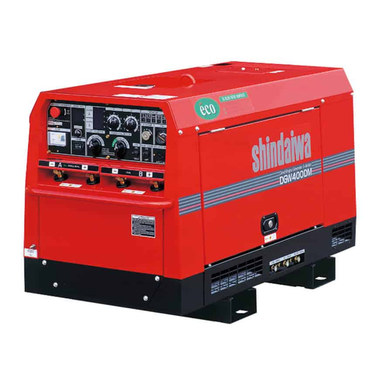
SOUND PROOF DIESEL ENGINE
GENERATOR/WELDER
DGW400DM-380A
Vertical, Water-Cooled
4-Cycle Diesel Engine
CAUTION: Do not operate the Generator/Welder, or any other appliance, before you
have read and understood the instructions for use.
Shindaiwa Corporation
Table of Contents
3.Use
Page
2
5
6
6
7
7
7
8
10
11
13
13
14
14
14
15
16
17
17
19
19
20
21
21
21
21
22
23
24
24
25
26
28
28
33
33
35
36
Advertisement
Table of Contents

Related Manuals for Shindaiwa DGW400DM-380A


Summary of Contents for Shindaiwa DGW400DM-380A
-
Page 1: Table Of Contents
5-4.Frequency Change SOUND PROOF DIESEL ENGINE 5-5.Earth Leakage Relay 5-6.Single Phase Breaker for GENERATOR/WELDER the receptacle circuit only 5-7.The Slow-Down Feature DGW400DM-380A 5-8.Voltage Adjusting Dial 6.Initialization and Pre-check Vertical, Water-Cooled 6-1.Checking Engine Oil 6-2.Checking Coolant/Water 4-Cycle Diesel Engine 6-3.Checking Fuel 6-4.Checking Fuel, Engine Oil... - Page 2 Introduction Thank you for purchasing Shindaiwa Sound Proof Diesel Engine Generator/Welder. This user manual was created to ensure the safe operation of this equipment. Therefore, the manufacturer of this equipment strongly recommends that the user follow the instructions herein, to avoid unnecessary accidents and repairs.
-
Page 3: Safety Guidelines
1. Safety Guidelines Danger : Suffocation from exhaust fume Exhaust fume from the engine contains many elements harmful to human. Do not operate this equipment in poorly ventilated area, such as inside a room or in a tunnel. Danger : Electric Shock Do not touch the output terminals during operation. - Page 4 Caution : Fire The equipment uses Diesel Oil as a fuel. When refueling, always stop the engine and keep away from fire. Moreover, always wait until the engine cools down before refueling. Always wipe any drip of Diesel fuel or lubrication oil. Do not use this equipment when a leak is found.
- Page 5 Location of Warning labels When the warning labels become unreadable or damaged, place new labels on the appropriate locations, as specified in the following figure. When ordering the label, use the following part numbers. Suffocation from exhaust fume (No. 19402-00194) Suffocation from welding fume (No.
-
Page 6: Specifications
2. Specifications Model DGW400DM Generating Method Rotating Field Rated Current (A) 370 / 390 Rated Voltage (V) 34.8 / 35.6 Duty Cycle Rated Speed (min 3000 / 3600 No Load Voltage (A) MAX 85 Single Current Adj. Range (A) 90 – 380 / 110 - 400 Welding Rod (Ф) 2.6 - 8.0 Dual... -
Page 7: Parts
3. Usage Arc Welding Electric Tools and Home Appliances Power Source for lights Caution : Damage to the equipment or other properties The equipment is designed for the above purposes only. Do not use it for the other purpose. When it will be used for the equipment with the microcomputers control or for the ultra-precision devices, the load may be malfunctioned. -
Page 8: Equipment
5. Equipment 5-1 Eco Welding The equipment is incorporated in Eco welding features that are aimed at performing the lower noise, the lower fuel consumption and the lower gas emission than conventional models. When you turn the selector switch to Eco, you will be able to weld with Max. 5.0mmφwelding rod at the slow down speed. -
Page 9: 5-3.Monitor Lamp
5-3 Monitor Lamp The equipment is incorporated in monitoring function of WATER TEMP, BATTERY CHARGING, OIL PRESSURE, Hz/OVERHEAT. Under normal condition, when the starter switch changes from STOP to RUN, all the lamps of BATTERY CHARGING, OIL PRESSURE and Hz/OVERHEAT turn ON. When the engine starts, all the lamps turn OFF. - Page 10 <Caution> The battery charge monitor cannot detect the degradation of the battery nor the battery fluid level. Check the battery fluid level periodically. (Refer to No. 6-5 Checking Battery) (3) Oil Pressure Monitor Lamp Danger : Injuries Close all doors and place locks during operating this equipment, to avoid injuries by unintentionally touching cooling fan and fan belt.
-
Page 11: 5-4.Frequency Change
5-4 Frequency Change Danger : Injuries Frequency change should be done, after stopping the engine. Moreover, close doors and place locks during operating this equipment, to avoid injuries by unintentionally touching cooling fan and fan belt. Danger: Electric Shock Never touch the frequency change bus bar during operation. Caution: Burns Do not touch the engine and muffler during operation and immediately after stopping the equipment, for the temperature can reach extremely high. -
Page 12: 5-5.Earth Leakage Relay
5-5 Earth Leakage Relay Danger : Electric Shock Ground every grounding terminal to the earth as set out in the manual. If even one of all is unconnected by mistake or accident, it will be much more dangerous for human body than the NO RELAY case, because leaking current inevitably goes through the body. - Page 13 (2) Operation Check Before operating the equipment, check always if the device can work duly as shown in the following procedure. Turn the starter switch from STOP to RUN. Turn (Push-up) the 3-P circuit breaker (lever) to ON position. Push the test button. The device is found to be normal as the earth leakage indication lamp turns ON and the 3-P circuit breaker positions in the middle of ON and OFF.
-
Page 14: 5-6.Single Phase Breaker For The Receptacle Circuit Only
5-6 Single Phase Breaker for the receptacle circuit only Caution : Electric Shock Injuries Be sure to disconnect all the loads to the generator when turning the breakers ON again, after the 1-Phase Breaker has activated. Disconnect all the loads. Turn the breaker to ON. -
Page 15: 5-8.Voltage Adjusting Dial
5-8 Voltage Adjusting Dial Adjust the dial whenever the AC Output adjustment is necessary. Set the dial in the center usually. <Caution> When raising the voltage, the current is decreasing. (Use the output within the output capacity.) In you raise the voltage exceeding the allowable voltage range, which causes the damage to the loads. -
Page 16: 6-2.Checking Coolant/Water
Selecting proper engine oil <Caution> Use the API class CC or higher. Viscosity and Temperature Temperature Over +20 +10 +20 -10 +40 Viscosity SAE30 SAE20 SAE10W/30 6-2 Checking Coolant / Water Danger : Injuries Close all doors and place locks during operating this equipment, to avoid injuries by unintentionally touching cooling fan and fan belt. -
Page 17: 6-3.Checking Fuel
(1) Filling to the Reservoir Tank Remove the sub tank cap. Fill up the sub tank to the FULL level. Install the cap back. (2) Filling to the Radiator Remove the top plate. Remove the radiator cap. Fill the radiator up to the top. Install the cap back and tighten. -
Page 18: 6-4.Checking Fuel, Engine Oil And Water Leakage
<Caution> Use Diesel fuel, ASTM D975 No.2-D in the event ambient temperature reaches down to -5 . The engine is designed to use either No.1-D or No.2-D Diesel fuel. However, for better economy, use No. 2-D Diesel Fuel whenever possible. At temperatures less than -7 (20 ), No.2-D fuel may pose operating problems (see “Cold Weather Operation which follows). - Page 19 Check the fluid level. If the level is near or lower than LOWER level, add distilled water until the fluid level reaches UPPER level. Make sure that the battery cables are firmly secured to the posts. Tighten the clamps if necessary. <Caution>...
-
Page 20: Operation
7. Operation Danger : Suffocation from exhaust fume Exhaust fume from the engine contains many elements harmful to human. Do not operate this equipment in poorly ventilated area, such as inside a room or in a tunnel. Caution : Suffocation from exhaust fume Do not point the exhaust fume toward pedestrians or building. -
Page 21: 7-2.Stopping
Restart after stopping due to fuel shortage This equipment is incorporated in automatic vacuuming air feature. Therefore, even though the engine stops due to running out of fuel, you can restart the engine easily by the following steps. Turn the starter switch to STOP. Fill the fuel. -
Page 22: Welding Operation
8. Welding Operation 8-1 Selection – Welding Cable Select the cable with proper gauge, based on the allowable amperage and the length, per the table shown below. The welding capacity is to reduce if the small gauge cable is used. <Caution>... -
Page 23: 8-4.Duty Cycle
Stop the engine. Connect a welding cable to a crimping terminal, a welding rod holder, and a material holder. Connect the welding cables to the output terminals per the table below. Eco (Single) Single Dual Welding Rod Welding Rod Welding Rod φ2.0 –... -
Page 24: 8-5.Welding
8-5 Welding Caution : Suffocation from welding fume Be sure to wear a fume proof mask in operation, because welding fume contains poisonous gas and dust. Pay attention to the airflow direction and sufficient ventilation also in order to prevent from inhaling the fume. Caution : Injuries to eyes and skin Be sure to wear spark protection glass(es)(Refer to the table below), long-sleeve shirts, gloves, etc. -
Page 25: Generator Operation
Adjust the current amperage by the current adjust dial, per the table below. Welding Current at the dial position Position Freq 1 Person 50Hz Single 60Hz 50Hz Dual 2 Persons 60Hz The values shown in the table are for reference only. The length and the ambient temperature affect the value. -
Page 26: 9-2.Output Limitation
9-2 Output Limitation Please refer to the following table, because electric tools and home appliances cannot be judged only by the rated output or the power consumption due to the efficiency and character of the components. Applicable Load (For reference purpose only) Capacity (kW) 1-Phase 1-Phase... -
Page 27: 9-3.Operation
9-3 Operation Danger : Electric Shock Before connecting or disconnecting a load cable from output terminals, always turn the circuit breakers (3-P and 1-P) to OFF position. And always stop engine, and remove the engine key. A person performing the maintenance should always keep the key. - Page 28 After the engine starts (Refer to 7-1 Starting ), operate the equipment as per the following procedures. Turn the power switch OFF in the load, and then turn the circuit breaker to OFF . Check to confirm that the breakers (3-P and 1-P) position OFF .
-
Page 29: Simultaneous Use Of Welding And Generating
10. Simultaneous Use of Welding and Generating The circuit breakers (3-P and 1-P) react on the AC power supply circuit only. In the simultaneous use of welding and generating, there sometimes happens overload to the engine. Refer to the following table and limit the AC power use. Limitation of AC Power Supply in the simultaneous use of welding and generating (60Hz) Welding Output AC Power Output... - Page 30 Checking Time Startup Every Every Every Every Every Checking Items Check 50hrs 1000 2000 hrs hrs. Check and Supply Fuel ○ Check and Supply Engine ○ Engine Oil Change after ○ ○ Oil Filter Change after ○ ○ Check/Add Water/Coolant ○...
- Page 31 (1) Oil Change First Time 50 hour mark or after Every 100 hours Remove the oil plug. Loosen the oil drain plug and allow the oil to drain fully. Reinstall the oil drain plug. Checking the oil level by the oil level gauge, add oil into the oil filler to fill up to the max level (about 5.0 liter).
- Page 32 Clean 50 hours and Every 100 hours afterwards Replace Every 400 hours Loosen the wing bolts in the air cleaner and remove the air element. Clean or replace the air element. <The element is adhered with dried contaminants> Blow up compressed air from inside the element. <The element is adhered with carbon or oil>...
- Page 33 Drain Water Every 200 hours Unscrew the fuel drain plug. Reinstall the drain plug, after draining water completely <Caution> Change the packing, whenever changing oil. Packing Part No.: 6C090-58961 (Kubota) (6) Changing Coolant/Water Replace Every 2 years or 2000 hours Total Coolant/Water Capacity: 4.3 liter, including sub tank cap.
-
Page 34: Long-Term Storage
12. Long-Term Storage Danger : Electric Shock Before performing any equipment check or maintenance, stop the engine, and remove the engine key. A person performing the maintenance should always keep the key. Caution : Injuries Before performing any equipment check or maintenance, stop the engine, and remove the engine key. - Page 35 Symptoms Possible Cause Corrective Actions Starter motor does not 1. Weak Battery 1. Recharge Battery start 2. Dead Battery 2. Replace Battery Engine does not start 1. Fuel lever to CLOSE 1. Fuel lever to OPEN 2. Insufficient Fuel 2. Replenish fuel 3.
-
Page 36: Engine Wiring Diagram
14. Engine Wiring Diagram - 35 -... -
Page 37: Generator Wiring Diagram
15. Generator Wiring Diagram - 36 -... - Page 38 Shindaiwa Corporation Head Office : Telephone: +81-82-849-2220 FAX: +81-82-849-2481 71905-94310 - 37 -...