Table of Contents
Advertisement
Quick Links
Advertisement
Table of Contents

Related Manuals for Shindaiwa EGW165M-I/UKV


Summary of Contents for Shindaiwa EGW165M-I/UKV
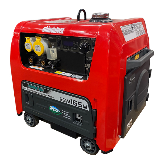
- Page 1 Original instructions OWNER’S AND OPERATOR’S MANUAL Air-Cooled, 4 Cycle OHV Engine CAUTION: Do not operate the Generator/Welder, or any other appliance, before you have read and understood the instructions for use. EGW165M-I/UKV X750-031 03 2 X750804-430 2...
- Page 3 Introduction Thank you for purchasing Shindaiwa Sound Proof Petrol Engine Generator/Welder. This Operator’s manual has been created to ensure the safe operation of this equipment. Therefore, the manufacturer of this equipment strongly recommends that the user follow the instructions herein, to avoid unnecessary accidents and repairs.
- Page 4 Symbol form/shape Symbol description/application Do not use for Indoor wiring Do not use in the rain Beware of eyes and skin Beware of hot surface Beware of high voltage Guaranteed sound power level Some of the items noted in [ Caution] may also lead to serious injuries.
- Page 5 Ohme, Tokyo 198-8760 JAPAN declares, under the sole responsibility thereof, that the hereunder specified new unit: SOUND PROOF PETROL ENGINE GENERATOR/WELDER Brand: Shindaiwa Type: EGW165M-I/UKV Serial Number M03301000055 to M03301999999 complies with: the requirements of Directive 2006/42/EC (use of harmonized standard...
-
Page 6: Table Of Contents
Table of Contents 1. Safety Guidelines ································································· 1 2. Specifications ····································································· 5 3. Use ···················································································· 6 4. Parts ·················································································· 7 5. Equipment ·········································································· 8 5-1. Earth Grounding Terminal ············································· 8 5-2. Frequency Changeover Switch ······································ 8 5-3. Engine Speed Control Switch (Eco-mode) ························ 8 5-4. -
Page 7: Safety Guidelines
1. Safety Guidelines Warning: Suffocation from exhaust fumes Exhaust fumes from the engine contain many elements harmful to humans. Do not operate this equipment in poorly ventilated areas, such as inside a room or in a tunnel. Warning: Electric Shock ... - Page 8 Warning: Fire The equipment uses Petrol as a fuel. When inspecting the equipment or refueling, always stop the engine, remove static electricity and keep away from sparks or naked flames. Always wait until the engine cools down before refueling. ...
- Page 9 Caution: Fire Do not connect AC output to any indoor wiring. Always wait until the equipment cools down, before covering for storage. Do not allow children near the equipment. Keep children at a safe distance from the machine at all times.
- Page 10 Location of Warning Labels When the warning labels become unreadable or damaged, place new labels on the appropriate locations, as specified in the following figure. When ordering the label, use the following part numbers. 1. Suffocation from Exhaust Fumes (X505-011481) 2.
-
Page 11: Specifications
2. Specifications Model EGW165M-I/UKV Generating Method Rotating Field, Synchronous AC Generator Rated Current (A) Rated Load Voltage (V) 25.8 Duty Cycle (%) @ 40°C Rated Speed (min 3600 75 (3800 min No Load Voltage (V) 54 (EN 60974-1:2012 Fig. 4, 3800 min... -
Page 12: Use
3. Use Arc welding (Manual welding only) Power source for electric tools Power source for lights EMC classification Group 2 Class A Caution: Damage to the equipment or other properties This product may cause interference if used in residential areas. Such use must be avoided unless the user takes special measures to reduce electromagnetic emissions to prevent interference to the reception of radio and television broadcasts. -
Page 13: Parts
4. Parts Choke 17. Air Cleaner (Cleaner Cover) AC Output Switch 18. Recoil Knob Frequency Changeover Switch 19. Fuel Inlet Display 20. Front Door Current Adjusting Dial 21. Side Door Engine Speed Control Switch 22. Plug Maintenance Cover Starter Switch 23. -
Page 14: Equipment
5. Equipment 5-1. Earth Grounding Terminal The grounding terminal of this equipment. Even though all the terminals of the loads have been grounded to the earth, this machine grounding terminal should be grounded to the earth. (Grounding resistance: 500 Ω or below) <Caution>... -
Page 15: Weld Mode Selector
5-4. Weld Mode Selector You can select a weld mode of [DROOP] or [CC] in accordance with the type of welding being performed. DROOP (Drooping Characteristic) The weld current can be adjusted by manipulating the welding rod due to being able Weld Mode Selector to increase or decrease the current for changing the arc length, thereby allowing you to adjust the arc status and weld beads. -
Page 16: Oil Sensor
After checking the engine has stopped completely, turn the engine on again, and then change the AC output switch to [ON] position. <Caution> Refer to 8-2 Output Limitation (P. 23) for a table showing maximum currents from the circuit. ... -
Page 17: Wheel Brake
(2) Welding current (pre-set/actual) Default display mode indicates pre-set welding current. (The pre-set welding current lamp turns on.) The display indicates actual welding current while welding. (The actual welding current lamp turns on.) (3) Oil warning If the engine oil sensor is activated during operation, the display will indicate [OIL]. Please refer to 5-7 Oil Sensor (P. -
Page 18: Earth Leakage Circuit Breaker And Grounding
(2) Unlock the wheel Wheel Unlock Slide the brake arm to position 1 and then down to default position 2. <Caution> Be sure to unlock the brake, before attempting to move the equipment to avoid a locking system malfunction. 5-10. -
Page 19: Operation
7. Be sure to set the AC output switch to [OFF] position before starting the engine. (3) The Earth Leakage Circuit Breaker has activated Warning: Electric Shock/Injuries Be sure to disconnect all the loads to the equipment before turning the ELCB ON again, after the earth leakage circuit breaker has activated. - Page 20 <Caution> You cannot measure the oil level accurately when the equipment is on an uneven surface. If the machine is placed on an uneven surface, it is still possible for the engine to run, however, the oil sensor may not detect accurately the true level of oil and this may cause engine failure.
- Page 21 (2) Checking Fuel Warning: Fire When checking and refueling fuel, always stop the engine, remove static electricity. Never fill fuel above the upper level. Always wipe away any drips of fuel. Check the fuel valve and add fuel if necessary. <Caution>...
- Page 22 <Caution> Tighten the ring more in order to prevent fuel leakage from the Fuel Strainer. Ring Fuel Strainer (4) Checking Battery Terminal Tightening Warning: Explosion The battery may emit some combustible gas. Keep it away from fire and sparks. ...
-
Page 23: Starting
6-2. Starting Warning: Suffocation from exhaust fume Exhaust fumes from the engine contain many elements harmful to humans. Do not operate this equipment in poorly ventilated areas, such as inside a room or in a tunnel. Warning: Fire Temperatures around the muffler and exhaust can reach extremely high levels. Keep flammable items (such as fuel, gas, paint, etc.) away from the equipment. - Page 24 <Caution> Never turn the starter switch to [START] position once the engine is running. 6. Push back the choke. <Caution> Just after starting, the engine may stop if the choke is prematurely pushed back in. In this case, push back the choke slowly once the engine is warm. 7.
-
Page 25: Stopping
6-3. Stopping ELCB AC Output Switch 1. Switch the AC output switch to [OFF] position. 2. Turn the idle control switch to [ECO] position. 3. Keep the engine idling for approximately 3 minutes to cool. 4. Turn the starter switch to [STOP] position. 5. -
Page 26: Connection-Welding Cable
7-3. Connection–Welding Cable Warning: Electric Shock Always examine welding cables, power cables and plugs etc., to ensure there are no defects present, prior to operation. Before connecting or disconnecting a welding cable from welding output terminals, stop the engine, and remove the starter key. A person performing this task must always keep the key. -
Page 27: Welding
7-5. Welding Warning: Electromagnetic Interference Persons using a heart pacemaker are not allowed near the Generator work area while the Generator is in operation without the permission of a doctor. The welder generates a magnetic field while energized that can negatively affect pacemaker operation. -
Page 28: Generator Operation
8. Generator Operation Warning: Electric Shock Do not operate the equipment, if the equipment or you are wet. Caution: Injuries Attach a plug to the receptacle of the equipment, after confirming the breaker is in the [OFF] position. ... -
Page 29: Operation
<Caution> Single phase AC output from the 29 and 16 amp sockets are as follows. 110 V, 16 A 110 V, 29 A Total current should be limited to within the rated current specification. 110 V, 16 A 110 V, 29 A ... -
Page 30: Checking And Maintenance
9. Checking and Maintenance Warning: Electric Shock/Injuries Before performing any equipment check or maintenance, stop the engine and remove the starter key. The person performing the maintenance must always keep the key. Warning: Fire Never operate the equipment close to naked flames. ... - Page 31 (1) Change Engine Oil First Time 20 hours mark Open to arrow direction 2nd or after Every 100 hours 1. Open the oil maintenance cover. 2. Put the oil saucer under the oil drain outlet. Press the Click to arrow direction 3.
- Page 32 (3) Clean and Change Air Cleaner Pull the Knob to arrow direction Clean Every 50 hours <Caution> Clean more frequently, if used in dusty environment. Knob Change the urethane part if the urethane part deteriorated with time. Side Door Open to arrow direction ...
- Page 33 Fuel Valve Seal Strainer Cup Strainer Ring (5) Clean Exhaust Wire Mesh Clean Every 500 hours 1. Loosen the bolt and remove the exhaust wire mesh and holder. 2. Clean off the carbon deposits from the exhaust’s wire mesh using a wire brush. 3.
-
Page 34: Long-Term Storage
Replacing the battery 1. Remove the clamp and the cable from the negative (-) post on the battery. (Always remove negative side first.) 2. Remove the clamp and cable from the positive (+) post on the battery. (Never touch the battery fixing plate to the terminals) 3. -
Page 35: Troubleshooting
4. Turn the fuel valve to [CLOSE] position and re-fit the strainer cup tight with the ring. <Caution> Be sure to check for any contaminants on the seal, whenever reinstalling the strainer cup. 5. Re-fit the fuel valve with the bolts. 6. - Page 36 Follow the guidelines below, when performing any troubleshooting. If you cannot resolve the problems by this method, contact our authorized distributor or our dealer to request the repair. Symptoms Presumed Cause Corrective Actions Starter motor does not 1. Weak Battery 1.
-
Page 37: Wiring Diagram
12. Wiring Diagram - 31 -... - Page 40 1-7-2 SUEHIROCHO, OHME, TOKYO 198-8760, JAPAN PHONE: 81-428-32-6118. FAX: 81-428-32-6145. ©2020 Printed in Japan...