
Related Manuals for Liebert GXT2-10000RT208


Summary of Contents for Liebert GXT2-10000RT208
- Page 1 AC Power For Business-Critical Continuity Liebert GXT2-10000RT208 ™ User Manual–10kVA, 60 Hz, 120/208/240V...
-
Page 3: Table Of Contents
ONFIGURATION ROGRAM GXT2-10000RT208 Configuration Program Features ......20 8.1.1 What You Will Need ............20... - Page 4 Configuration Program—Installation ......... . . 21 Establishing Communication Link with the UPS .
- Page 5 11.1 Communications Interface Port..........32 11.1.1 DB-9 Interface Port .
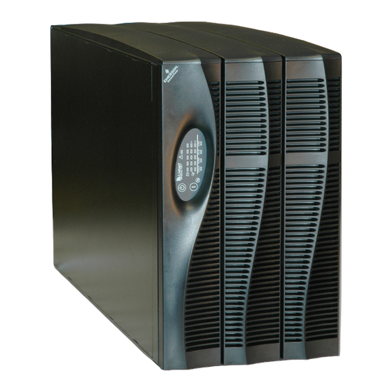
- Page 6 FIGURES Figure 1 10 kVA Dual Inverter GXT 2 (front and rear views) ........7 Figure 2 Internal battery pack and connector .
-
Page 7: Important Safety Instructions
Do not continue to use the UPS if the front panel indications are not in accordance with these operating instructions or if the UPS performance alters in use. Refer all faults to your local dealer, Liebert representative or the Liebert Worldwide Support Group. - Page 8 When replacing batteries, replace with the same Liebert authorized replacement battery kits. When replacing power module, replace with the same Liebert authorized replacement power module kit. CAUTION Do not dispose of battery or batteries in a fire. The battery may explode.
-
Page 9: Glossary Of Symbols
Glossary of Symbols LOSSARY OF YMBOLS Risk of electrical shock Indicates caution followed by important instructions AC input AC output Requests the user to consult the manual Indicates the unit contains a valve-regulated lead acid battery PbH2SO4 Recycle DC voltage Equipment grounding conductor Bonded to ground AC voltage... -
Page 10: Introduction And System Description
The UPStation GXT2-10000RT208 has an interface port for communication between the UPS and a network server or other computer systems. This port provides detailed operating information includ- ing voltages, currents and alarm status to the host system when used in conjunction with Liebert’s MultiLink™ software. MultiLink software can also control UPS operation remotely. -
Page 11: System Description
Battery Charger The battery charger utilizes energy from the utility power and precisely regulates it to continuously float charge the batteries. The batteries are being charged whenever the UPStation GXT2-10000RT208 is plugged in, even when the UPS is not turned on. -
Page 12: Dc To Dc Converter
(20°C to 25°C). Optional external battery cabinets are available to extend battery run times. Static Bypass The UPStation GXT2-10000RT208 provides an alternate path for utility power to the connected load in the unlikely event of a UPS malfunction. Should the UPS have an overload, overtemperature or UPS failure condition, the UPS automatically transfers the connected load to bypass. -
Page 13: Major Components
Major Components AJOR OMPONENTS The GXT2-10000RT208 is composed of three major assemblies to provide easier handling, installation and versatility. Main Frame and Electronics This 6U cabinet arrives without internal batteries to lighten the UPS for easier installation. Once the cabinet has been placed in its final floor or rack position, the internal batteries may be installed. The UPS is shipped with standard hardwire terminal blocks for input and output connections. -
Page 14: Input/Output Terminal Blocks And Optional Output Distribution
Major Components Input/Output Terminal Blocks and Optional Output Distribution The UPS is shipped with hardwire terminal blocks. For maximum flexibility, additional distribution options are available that provide the benefit of output receptacle convenience. Figure 3 Hardwire terminal blocks INPUT OUTPUT Figure 4 Optional output distribution modules PD-101... -
Page 15: What S Included
What’s Included ’ NCLUDED The GXT2-10000RT208 is shipped with Box containing accessories is shipped in the UPS’ these items: battery compartment • GXT2-10000RT208 user manual • Vertical display overlay • Front bezels - 3 • Top bezels - 3 • Battery cover grille •... -
Page 16: Installation And Configuration
UPS operation in sustained temperatures above 77°F (25°C) reduces battery life. Install the Main Cabinet The GXT2-10000RT208 may be installed either as a tower unit or in a rack, depending on available space and use considerations. Determine the type of installation and follow the appropriate instruc- tions in either 6.1.1 - Tower UPS Installation or 6.1.2 - Installing the Adjustable Rack-Mount... -
Page 17: Installing The Adjustable Rack-Mount Kit-Sold Separately
This kit contains parts needed to mount several different models of UPS and external battery cabi- nets into EIA310-D standard four-post racks that are 18-32" deep (457-813mm). The weight limit per pair of adjustable rack-mounting brackets is 200 pounds (91 kg). Liebert rack-mount bracket kit, part # RMKIT18-32, includes: Item Quantity... - Page 18 Installation and Configuration 4. Get eight (8) M4 screws and eight (8) M4 nuts from the M4 nuts hardware pack in this kit. Each nut has a locking, nylon screws insert that begins gripping the screw when it is halfway tight.
-
Page 19: External Battery Cabinet Installation
Installation and Configuration External Battery Cabinet Installation Optional Liebert external battery cabinets may be connected to the UPS to provide additional battery run time. External battery cabinets are designed to be placed on one side of the UPS or stacked beneath the UPS. -
Page 20: Connect Input/Output Power
Installation and Configuration Connect Input/Output Power The UPS has hardwire terminal blocks for input and output electrical connections. Optional output distribution modules permit connecting additional loads to the UPS. These optional plug-and-play distribution modules offer different types and numbers of connection plugs. WARNING The UPS must be completely powered down before beginning to make these electrical connections. -
Page 21: Input & Output Terminal Block Connections
Installation and Configuration 6.3.2 Input & Output Terminal Block Connections Conduit entry holes are provided on the rear and side of the box. Input and output wiring should not share the same conduit. Table 1 Electrical requirements Recommended Wire Maximum Wire Terminal Input Current Recommended (Max.) External... -
Page 22: Add An Output Power Distribution Module-Optional
Installation and Configuration 6.3.3 Add an Output Power Distribution Module—Optional To add an optional output distribution module to the GXT2 10000RT208: 1. Remove the four screws securing the blank output distribution cover plate to the rear of the UPS. The cover is at top left corner in the tower configuration and at the bottom left in the rack configuration. -
Page 23: Install The Internal Battery Packs
Installation and Configuration Install the Internal Battery Packs To facilitate shipping and installation, the GXT2-10000RT208 ships without the internal battery packs installed. Once the UPS is installed in place, the internal battery packs must be installed. Controls and Indicators (horizontal overlay) -
Page 24: Initial Startup And Electrical Checks
Initial Startup and Electrical Checks NITIAL TARTUP AND LECTRICAL HECKS Initial Startup and the Configuration Program—The UPS ships with a default 120 VAC L-N setting. This is also the most robust setting in that it can operate with either input phase angle (120 or 180 degrees). -
Page 25: Output Receptacle Distribution Options
Initial Startup and Electrical Checks Figure 7 Hardwire terminal connections INPUT OUTPUT Output Receptacle Distribution Options WARNING A qualified electrician should install the optional output distribution. 1. Verify that the input feeder circuit breaker is off. 2. Verify that the input and output circuit breakers are off. 3. -
Page 26: Configuration Program
8.1.1 What You Will Need In addition to the GXT2-10000RT208 UPS, you will need the configuration program compact disk and serial cable (beige or tan, three-wire: GND, TX, RX; straight through 2-2, 3-3, 5-5) included in the ® UPS accessory box. A computer—desktop or laptop—running Windows 95 or later is also required to set up and run the configuration program. -
Page 27: Configuration Program-Installation
2. When you see this PreSetup window, select OK. This will open the main installation screen. 3. Click NEXT to continue installing the configuration program. Liebert recommends using the default installation options, but you will be given the option to make modifications to the standard entries. -
Page 28: Establishing Communication Link With The Ups
Configuration Program Establishing Communication Link with the UPS Use only the serial communication cable supplied with the configuration program. NOTE If an accessory communication card has been installed in the UPS’s communication card slot, the option card must be removed while using the configuration program. Use the serial communication cable to connect your computer’s COM1 port to the DB-9 communica- tion port on the rear of the UPS. -
Page 29: Configuration Program-Operation
Configuration Program Configuration Program—Operation 8.4.1 Read/Confirm UPS Configuration Settings The UPS settings may be monitored, but not changed, using the configuration program while the UPS is operating in any mode. If the program is only used to read the present UPS settings, close the pro- gram using the CANCEL button. -
Page 30: Ups Tab
Configuration Program UPS Tab When the program starts, the following window will open displaying the UPS model along with the current UPS settings. This information can be updated at any time using the REFRESH button. Figure 8 Factory default settings for 120VAC UPS 8.5.1 Output Voltage The Output Voltage displayed is the nominal input/output voltage. -
Page 31: Options Tab
Configuration Program Options Tab Computer users may choose to use versatile com- puter shutdown software that communicates with the UPS via a serial communications cable. The Options tab should not be used to modify the UPS functions for such applications. For some industrial applications and special computer applications, the UPS may be moni- tored and controlled using external voltages and... -
Page 32: Options Tab Used With Earlier Gxt 2U Models
Configuration Program Options Tab Used With Earlier GXT 2U Models This version of the configuration program will accompany GXT 2U UPS models that support new pro- gramming features accessible using the Options tab. If version 1.6 (or later) is used with an earlier GXT 2U model (with an earlier UPS firmware version), the Any Mode Shutdown features cannot be changed. -
Page 33: Battery Tab
The boxes on the right show the available options using the drop-down selection boxes. The GXT2-10000RT208 automatically detects external battery cabinets when they are connected. Use the Battery Cabinets Number selection box to select non-Liebert battery cabinets when used with the UPS. 8.8.1 Low Battery Time Warning The UPS will estimate remaining operating time when on batteries. -
Page 34: About Tab
Configuration Program About Tab The version number of the configuration program may be confirmed using the About Tab. -
Page 35: Controls And Indicators
ON - Pressing this button will start up the UPS in order to provide conditioned and protected power. Alarm Silence - To silence alarms, press this button for at least one Second. After the alarm is silenced, the UPStation GXT2-10000RT208 will reactivate the alarm system to alert of additional problems. NOTE The LOW BATTERY and BYPASS reminder alarms CANNOT be silenced. -
Page 36: L1 & L2 Load Level Indicators (Two Rows Of Indicators: 4 Green, 1 Amber)
The Battery Level indicators display approximate battery capacity at all times. Each indicator repre- sents an approximate 20 percent increase in battery capacity. The UPStation GXT2-10000RT208 is equipped with automatic and remote battery test features. The automatic test occurs every 14 days (this option is user-configurable) if utility has not been inter- rupted. -
Page 37: Modes Of Operation
Modes of Operation 10.0 M ODES OF PERATION 10.1 Normal Mode Operation During normal operation, utility power provides energy to the UPS. The filters, power factor correction circuit and the inverter process this power to provide computer grade power to connected loads. The UPS maintains the batteries in a fully charged state. -
Page 38: Communications
OMMUNICATIONS 11.1 Communications Interface Port The UPStation GXT2-10000RT208 UPS has a standard DB-9 serial port female connector located on the rear of the UPS unit. Several signals are provided on this port and are assigned as follows: Table 2 DB-9 pin assignment... -
Page 39: Pin 4 - Remote Shutdown On Battery
2. Pin 4 requires a 5-12 VDC signal to shutdown. This normally comes form the serial port using Liebert’s contact closure cable. It cannot be used with just a contact closure unless the relay is used to switch a voltage source. A 5-12 VDC signal for 1.5 seconds or greater is required to signal a shutdown. -
Page 40: Remote Emergency Power Off
Communications 11.4 Remote Emergency Power Off The UPS is equipped with a Remote Emergency Power Off (REPO) connector. The user must supply a means of interfacing with the REPO circuit to allow disconnecting the UPS input feeder breaker to remove all sources of power to the UPS and connected equipment to comply with national and local wiring codes and regulations. -
Page 41: Maintenance
Failure to recharge the batteries peri- odically will permanently degrade battery capacity. The UPStation GXT2-10000RT208 is designed to allow the user to safely replace the internal batter- ies. Read the safety cautions before proceeding. Contact your local dealer or Liebert representative to obtain the appropriate replacement battery kit part number and pricing. -
Page 42: Ups Power Module Replacement
Maintenance 12.2 UPS Power Module Replacement CAUTION The UPS must be switched to manual bypass before personnel begin to replace the power module. NOTE During the procedure, the connected load will not be protected from power disturbances, such as spikes, sags and failure. To remove the UPS power module without shutting off power to the connected load: 1. -
Page 43: Figure 11 Ups Back Panel-Control Location
Maintenance Figure 11 UPS back panel—control location Input Output Bypass Inverter Output Breaker 60A 250V~/T Input Breaker 60A 250V~/T Figure 12 Power module replacement Power module pulled out of UPS (Retaining grilles removed for clarity) -
Page 44: Troubleshooting
ROUBLESHOOTING The information below indicates various symptoms a user may encounter in the event the UPStation GXT2-10000RT208 develops a problem. Use this information to determine whether external factors caused the problem and how to remedy the situation. 1. The Fault indicator will illuminate, indicating the UPS has detected a problem. -
Page 45: Table 4 Alarm Conditions
5 minutes while the battery charger is not operational. If a problem persists, consult your local dealer, Liebert representative or contact the Liebert World- wide Support Group. Please have the UPS model number and serial number available at the time of your inquiry. -
Page 46: Table 5 Troubleshooting Guide
Wait 30 minutes to allow UPS to cool, then restart UPS. illuminated. condition. Load is on bypass If UPS does not restart, contact your local dealer, Liebert power. representative or the Liebert Worldwide Support Group. Fault and Bypass indicators UPS internal DC bus UPS requires service. - Page 47 Liebert representative or the Liebert Worldwide Support Group. Fault indicator and diagnostic UPS requires service. Contact your local dealer, Liebert indicators D and E are UPS charger fault. Representative or the Liebert Worldwide Support Group.
-
Page 48: Table 6 Battery Run Times
Troubleshooting Using the configuration program, the user may specify the number of GXT2-288VBATT external bat- tery cabinets attached to the UPS. The factory default is programmed for internal batteries only. Table 6 shows estimated run times at different loads. Table 6 Battery run times Battery/External 10000VA Run Time... -
Page 49: Auto-Learning Battery Run Times
13.1 Auto-Learning Battery Run Times As batteries age, the estimated run times may become less accurate. The GXT2-10000RT208 is pro- grammed to “learn” from a full battery discharge and modify the estimated run time for the measured battery capacity. This can improve accuracy and compensate for aging batteries or batteries that operate at different ambient temperatures. -
Page 50: Specifications
Specifications 14.0 S PECIFICATIONS Table 7 UPS specifications Model Number GXT2-10000RT208 8000W/8660VA at 127/220 (120 or 240 degrees only) 8000W/8660VA at 120/208 (120 or 240 degrees) 8000W/10000VA at 120/240 (180 degrees) Model Rating 8000W/10000VA at 115/230 (180 degrees only) 7200W/9000VA at 110/220 (180 degrees only) -
Page 51: Table 8 Battery Specifications
Specifications Table 7 UPS specifications (continued) Model Number GXT2-10000RT208 Bypass Protection Limits Disable Bypass operation If input voltage exceeds ±15% of the nominal voltage Re-enable Bypass operation If input voltage returns to within ±10% of nominal output voltage Disable Bypass operation... -
Page 52: Table 10 Optional Output Distribution Specifications-Pd-102
Table 11 External battery cabinet specifications Model Number GXT2-288RTVBATT Used w/ UPS Model GXT2-10000RT208 DIMENSIONS, Rack Mount, W x D x H Unit (with bezel), in (mm) 16.93 x 25.98 x 7 (430 x 660 x 178); 4U Shipping, in (mm) 22.64 x 33.46 x 12.40 (575 x 850 x 315) -
Page 53: Table 12 Replacement 10Kva Power Module Specifications
Specifications Table 12 Replacement 10kVA power module specifications Model Number GXT2-10KPWR208 DIMENSIONS in (mm) Shipping W x D x H 22.04 x 28.14 x 9.88 (560 x 715 x 251) WEIGHT lb (kg) Shipping 59.5 (27) ENVIRONMENTAL Storage Temp -5°F to +122°F (-15°C to +50°C) Relative Humidity 0% to 95%, non-condensing Storage Elevation... -
Page 54: Product Warranty Registration
• Visit the Quick Links section of our Web site at: http://www.liebert.com • Click on Product Warranty Registration and fill in the form. If you have any questions, please contact us at: US: 800-222-5877 Outside the US: 614-841-6755 upstech@emersonnetworkpower.com Contact Liebert Global Services at: US: 800-LIEBERT (800-543-2378) powertech@emersonnetworkpower.com... - Page 56 All rights reserved throughout the world. Specifications subject to change Hong Kong without notice. 852 2572220 ® Liebert and the Liebert logo are registered trademarks of Liebert Corporation. All names referred to are trademarks Fax: 852 28029250 or registered trademarks of their respective owners.