Table of Contents
Advertisement
Quick Links
Advertisement
Table of Contents
Troubleshooting

Related Manuals for Liebert GXT2-6000 RT208


Summary of Contents for Liebert GXT2-6000 RT208
- Page 1 OWER VAILABILITY ™ GXT2-6000RT208 ANUAL 120/208V 120/240V...
-
Page 3: Table Of Contents
MPORTANT AFETY NSTRUCTIONS LOSSARY OF YMBOLS NTRODUCTION AND YSTEM ESCRIPTION Transient Voltage Surge Suppression (TVSS) and EMI/RFI Filters....5 Rectifier/Power Factor Correction (PFC) Circuit ........5 Inverter . - Page 4 ONFIGURATION ROGRAM GXT2-6000RT208 Configuration Program Features ....... 19 8.1.1 What You Will Need ............19 Configuration Program—Installation .
- Page 5 10.0 ODES OF PERATION 10.1 Normal Mode Operation............30 10.2 Battery Mode Operation .
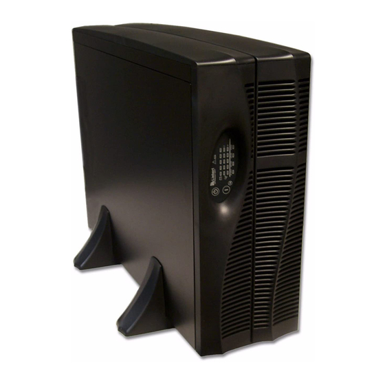
- Page 6 Figure 1 6 kVA Dual Inverter GXT 2U (front and rear views) ........7 Figure 2 Support base and spacers .
-
Page 7: Important Safety Instructions
Do not continue to use the UPS if the front panel indications are not in accordance with these operating instructions or if the UPS performance alters in use. Refer all faults to your local dealer, Liebert representative or the Liebert Worldwide Support Group. - Page 8 When replacing batteries, replace with the same Liebert authorized replacement battery kits. CAUTION Do not dispose of battery or batteries in a fire. The battery may explode. Do not open or mutilate the battery or batteries. Released electrolyte is harmful to skin and eyes. It may be toxic.
-
Page 9: Glossary Of Symbols
Glossary of Symbols LOSSARY OF YMBOLS Risk of electrical shock Indicates caution followed by important instructions AC input AC output Requests the user to consult the manual Indicates the unit contains a valve-regulated lead acid battery PbH2SO4 Recycle DC voltage Equipment grounding conductor Bonded to ground AC voltage... -
Page 10: Introduction And System Description
The UPStation GXT2-6000RT208 has an interface port for communication between the UPS and a network server or other computer systems. This port provides detailed operating information includ- ing voltages, currents and alarm status to the host system when used in conjunction with Liebert’s MultiLink™ software. MultiLink software can also control UPS operation remotely. -
Page 11: System Description
YSTEM ESCRIPTION Input TVSS & EMI/RFI Filters Transient Voltage Surge Suppression (TVSS) and EMI/RFI Filters These UPS components provide surge protection and filter both electromagnetic interference (EMI) and radio frequency interference (RFI). They minimize any surges or interference present in the util- ity line and keep the sensitive equipment protected. -
Page 12: Dc To Dc Converter
DC to DC Converter The DC to DC converter utilizes energy from the battery system and raises the DC voltage to the opti- mum operating voltage for the inverter. This allows the inverter to operate continuously at its opti- mum efficiency and voltage, thus increasing reliability. Battery The UPStation GXT2-6000RT208 utilizes valve-regulated, nonspillable, flame retardant, lead acid batteries. -
Page 13: Major Components
AJOR OMPONENTS The GXT2-6000RT208 is composed of three major assemblies to provide easier handling, installation and versatility. Main Frame and Electronics This 4U cabinet arrives without internal batteries to lighten the UPS for easier installation. Once the cabinet has been placed in its final floor or rack position, the internal batteries may be installed. The UPS is shipped with a basic hardwire distribution box. -
Page 14: Removable Power Distribution Box
Major Components Removable Power Distribution Box The UPS is shipped with a basic hardwire power distribution pack installed. For maximum flexibility, this may be easily replaced with either of two optional power distribution boxes that provide the ben- efits of hardwire input and output plus manual bypass switch or plug/receptacle convenience with manual bypass switch. -
Page 15: What
10 ft (3m) GEC connector Ferrite beads (2) What’s Included Battery cover grille Rack mount handles www.liebert.com GXT 2U™ Configuration Program For use with LiebertGXT2U model UPS systems Version 1.6 For Windows 95/98/NT To Install: Choose the Start button on the Taskbar... -
Page 16: Installation And Configuration
7.0 - Initial Startup and Electrical Checks. Visually inspect the UPS for freight damage. Report damage to the carrier and your local dealer or Liebert representative. CAUTION The UPS is heavy (see 14.0 - Specifications). Take proper precautions when lifting or moving it. -
Page 17: Installing The Adjustable Rack-Mount Kit-Sold Separately
6.1.2 Installing the Adjustable Rack-Mount Kit—Sold Separately This kit contains parts needed to mount several different models of UPS and external battery cabi- nets into EIA310-D standard four-post racks that are 18-32" deep (457-813mm). The weight limit per pair of adjustable rack-mounting brackets is 200 pounds (91 kg). Parts included are: Item Rear bracket members... - Page 18 4. Get eight (8) M4 screws and eight (8) M4 nuts from the hardware pack in this kit. Each nut has a locking, nylon insert that begins gripping the screw when it is halfway tight. Make sure to tighten the nut and screw completely to ensure locking action.Fasten the rear member and the front member together using (4) screws and (4) nuts per bracket assembly as shown in at right.
-
Page 19: External Battery Cabinet Installation
External Battery Cabinet Installation Optional Liebert external battery cabinets may be connected to the UPS to provide additional battery run time. External battery cabinets are designed to be placed on one side of the UPS or stacked beneath the UPS. -
Page 20: Connect Input/Output Power
Connect Input/Output Power The UPS ships with the basic hardwire box attached. If an optional model is to be used, remove the standard box and install the optional box using the three captive mounting screws marked in the illustration, below, right. 6.3.1 Replacing a power distribution box Whenever a power distribution box is not attached to a UPS,... -
Page 21: Pd-Hdwr And Pd-Hdwr-Mbs Terminal Block Connections
6.3.3 PD-HDWR and PD-HDWR-MBS Terminal Block Connections Conduit entry holes are provided on the rear and side of the box. Input and output wiring should not share the same conduit. Table 1 Electrical requirements—PD-HDWR and PD-HDWR-MBS Input Current Recommended (Max.) Rating External Overcurrent Protection... -
Page 22: Install The Grounding Electrode Conductor
Install the Grounding Electrode Conductor A Grounding Electrode Conductor must be attached to the rear panel using the M5x12 Phillips screw provided. This connection is required in addition to the power input ground connection to the remov- able power distribution box. Install an 8 AWG (10 mm 250-94) grounding electrode conductor to the nearest effectively grounded metal structural member, nearest effectively grounded metal water pipe or other grounding electrode in the grounding electrode... -
Page 23: Initial Startup And Electrical Checks
NITIAL TARTUP AND Initial Startup and the Configuration Program—The UPS ships with a default 120 VAC L-N setting. This is also the most robust setting in that it can operate with either input phase angle (120 or 180 degrees). Perform initial system checks first. If the UPS configuration needs to be modified for your application, then go to the next section to review use of the configuration program. -
Page 24: L14-30P Plug-In Connections-Including The Pd-001 Distribution Box
L14-30P Plug-in Connections—Including the PD-001 Distribution Box WARNING Miswiring power to the input (L1-L2-N-G) or connecting to single phase voltages (L-N-G only) may damage the UPS. A qualified electrician should verify that the L14-30R is properly wired before attaching the UPS. If the configuration program has been used to set the L-N voltage at 100, 110 or 115, then the input phase angle is required to be 180 degrees. -
Page 25: Configuration
• Specify the number of external battery cabinets connected to the UPS to adjust the remaining run time calculations reported by Liebert software products • Modify the shutdown setting of DB-9 pin 6 (for information on pin assignments, see 11.0 - Com- munications) 8.1.1... -
Page 26: Configuration Program-Installation
2. When you see this PreSetup window, select OK. This will open the main installation screen. 3. Click NEXT to continue installing the configuration program. Liebert recommends using the default installation options, but you will be given the option to make modifications to the standard entries. -
Page 27: Establishing Communication Link With The Ups
Establishing Communication Link with the UPS Use only the serial communication cable supplied with the configuration program. If an accessory communication card has been installed in the UPS’s communication card slot, the option card must be removed while using the configuration program. Use the serial communication cable to connect your computer’s COM1 port to the DB-9 communica- tion port on the rear of the UPS. -
Page 28: Configuration Program-Operation
Configuration Program—Operation 8.4.1 Read/Confirm UPS Configuration Settings The UPS settings may be monitored, but not changed, using the configuration program while the UPS is operating in any mode. If the program is only used to read the present UPS settings, close the pro- gram using the CANCEL button. -
Page 29: Ups Tab
UPS Tab When the program starts, the following window will open displaying the UPS model along with the current UPS settings. This information can be updated at any time using the REFRESH button. Figure 4 Factory default settings for 120VAC UPS 8.5.1 Output Voltage The Output Voltage displayed is the nominal input/output voltage. -
Page 30: Frequency Selection
8.5.4 Frequency Selection The UPS is normally designed for 50Hz or 60Hz operation. The factory default corresponds to the model. All models are capable of being used as 50Hz or 60Hz systems. The UPS will automatically sense the utility frequency when first plugged in and set the nominal frequency to match. Therefore, for all normal use the Auto Sense button should be selected. -
Page 31: Options Tab Used With Earlier Gxt 2U Models
Configuration Program Options Tab Used With Earlier GXT 2U Models This version of the configuration program will accompany GXT 2U UPS models that support new pro- gramming features accessible using the Options tab. If version 1.6 (or later) is used with an earlier GXT 2U model (with an earlier UPS firmware version), the Any Mode Shutdown features cannot be changed. -
Page 32: Battery Tab
Battery Tab Factory default settings illustrated. The boxes on the right show the available options using the drop-down selection boxes. 8.8.1 Low Battery Time Warning The UPS will estimate remaining operating time when on batteries. A low battery alarm is activated if the estimated time reaches the Low Battery Time. -
Page 33: About Tab
Configuration Program About Tab The version number of the configuration program may be confirmed using the About Tab. -
Page 34: Controls And Indicators
• After 24 hours, retest the batteries. • After the batteries have been retested, if only three of the five Battery indicators illuminate, con- tact your local dealer, Liebert representative or Liebert Worldwide Support Group. OFF/Bypass Button This button controls output power to connected load(s) and has dual functions: OFF and Bypass. -
Page 35: L1 & L2 Load Level Indicators (Two Rows Of Indicators: 4 Green, 1 Amber)
L1 & L2 Load Level Indicators (Two Rows of Indicators: 4 Green, 1 Amber) The Load Level indicators display the approximate electrical load placed upon both output legs of the UPS at all times. Each indicator represents an approximate 25 percent increase in load. For optimum utilization of the UPS, distribute L-N loads to approximately balance the loads on L1 and L2. -
Page 36: Odes Of Peration
10.0 M ODES OF PERATION 10.1 Normal Mode Operation During normal operation, utility power provides energy to the UPS. The filters, power factor correction circuit and the inverter process this power to provide computer grade power to connected loads. The UPS maintains the batteries in a fully charged state. -
Page 37: Communications
11.0 C OMMUNICATIONS 11.1 Communications Interface Port The UPStation GXT2-6000RT208 UPS has a standard DB-9 serial port female connector located on the rear of the UPS unit. Several signals are provided on this port and are assigned as follows: Table 3 DB-9 pin assignment DB-9 Assignment Description... -
Page 38: Pin 4 - Remote Shutdown On Battery
2. Pin 4 requires a 5-12 VDC signal to shutdown. This normally comes form the serial port using Liebert’s contact closure cable. It cannot be used with just a contact closure unless the relay is used to switch a voltage source. A 5-12 VDC signal for 1.5 seconds or greater is required to signal a shutdown. -
Page 39: Remote Emergency Power Off
11.4 Remote Emergency Power Off The UPS is equipped with a Remote Emergency Power Off (REPO) connector. The user must supply a means of interfacing with the REPO circuit to allow disconnecting the UPS input feeder breaker to remove all sources of power to the UPS and connected equipment to comply with national and local wiring codes and regulations. -
Page 40: Maintenance
The UPStation GXT2-6000RT208 is designed to allow the user to safely replace the internal batteries. Read the safety cautions before proceeding. Contact your local dealer or Liebert representative to obtain the appropriate replacement battery kit part number and pricing. -
Page 41: Ups Replacement
12.2 UPS Replacement When using a power distribution box with bypass, the UPS can be removed while powering the load through the Bypass Switch. NOTE During the procedure, the connected load will not be protected from power disturbances, such as spikes, sags and failure. To remove the UPS without shutting off power to the connected load: 1. -
Page 42: Troubleshooting
5 minutes while the battery charger is not operational. If a problem persists, consult your local dealer, Liebert representative or contact the Liebert World- wide Support Group. Please have the UPS model number and serial number available at the time of your inquiry. -
Page 43: Alarm Conditions
Wait 30 minutes to allow UPS to cool, then restart UPS. If UPS does not restart, contact your local dealer, Liebert representative or the Liebert Worldwide Support Group. Troubleshooting Alarm... - Page 44 Cause UPS requires service. Contact your local dealer, Liebert representative or the Liebert Worldwide Support Group. UPS requires service. Contact your local dealer, Liebert Representative or the Liebert Worldwide Support Group.
-
Page 45: Table 7 Battery Run Times
Using the configuration program, the user may specify the number of GXT2-144VBATT external bat- tery cabinets attached to the UPS. The factory default is programmed for internal batteries only. Table 7 shows estimated run times at different loads. Table 7 Battery run times Battery/External Cabinets Internal Battery... -
Page 46: Auto-Learning Battery Run Times
13.1 Auto-Learning Battery Run Times As batteries age, the estimated run times may become less accurate. The GXT2-6000RT208 is pro- grammed to “learn” from a full battery discharge and modify the estimated run time for the measured battery capacity. This can improve accuracy and compensate for aging batteries or batteries that operate at different ambient temperatures. -
Page 47: Specifications
14.0 S PECIFICATIONS Table 8 UPS specifications Model Number Model Rating DIMENSIONS in (mm) Unit W x D x H in. (mm) Shipping W x D x H in. (mm) WEIGHT lbs (kg) Unit Shipping INPUT AC PARAMETERS Nominal Operating Frequency Factory Default VAC L1-L2 Factory Default Input Phase Angle... -
Page 48: Table 9 Battery Specifications
Table 8 UPS specifications (continued) Model Number ENVIRONMENTAL Operating Temp Storage Temp Relative Humidity Operating Elevation Storage Elevation Audible Noise AGENCY Safety RFI/EMI Surge Immunity Transportation Table 9 Battery specifications Model Number DIMENSIONS in (mm) Shipping W x D x H in. (mm) WEIGHT lbs (kg) Unit Shipping... -
Page 49: Product Warranty Registration
Product Warranty Registration To register for warranty protection: • Visit the Quick Links section of our Web site at: http://www.liebert.com • Click on Product Warranty Registration and fill in the form. If you have any questions, please contact us at:... - Page 50 Specifications...
- Page 52 GXT2-6000RT208 The Company Behind the Products With over a million installations around the globe, Liebert is the world leader in computer protection systems. Since its founding in 1965, Liebert has developed a complete range of support and protection systems for sensitive electronics: •...