Table of Contents
Advertisement
ISO 9001
Use
Landis & Staefa Division
Flame Safeguards
Flame safeguards for burners with intermittent operation.
For safety reasons - self-test of flame supervision circuit, etc. - at least one controlled
shutdown is required every 24 hours.
For flame supervision systems for continuous operation, refer to data sheet 7783.
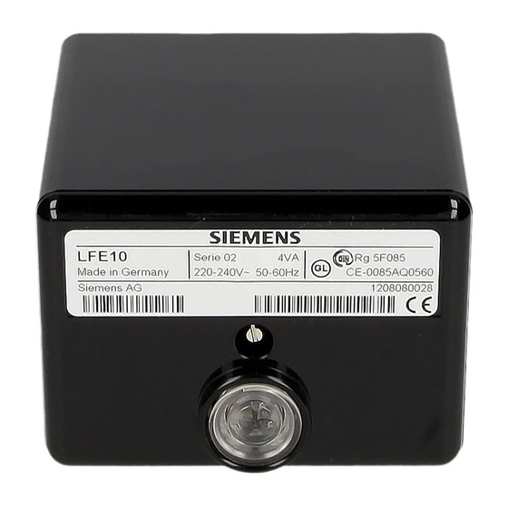
The LAE10 is used for the supervision and indication of oil flames, the LFE10
for gas and oil flames.
The LAE10 / LFE10 and this data sheet are intended for use by OEMs which
integrate the flame safeguards in their products.
The LAE10 is designed for the supervision of oil flames in connection with selenium
photocell detectors RAR...
The LFE10 is suited for the supervision of gas flames and luminous or blue-burning oil
flames in connection with UV detectors QRA... or a flame rectification probe.
Both types of flame safeguards are used primarily in conjunction with the LEC1 burner
control on the following applications:
– Dual-supervision of burners
Supervision of the main flame or of the pilot and main flame by two identical or
different types of flame detectors
– Supervision of forced draught oil / gas burners
Supervision of the flame with different types of detectors, depending on the
operating mode
– Multi-flame supervision
Plants with several burners whose flames must be supervised individually by one or
several detectors, whose startup and supervision, however, should or must be
carried out centrally and simultaneously by only one burner control
– The flame safeguards can also be used in connection with other types of burner
controls provided the given combination and selected circuitry do not impair the
burner control's safety functions
– The flame safeguards are also used as flame indication units in combustion plant
with manual startup
CC1N7781E
June 01, 1999
7
Supplementary data sheets 7712 and 7713
781
Series 02
1/8
Advertisement
Table of Contents

Related Manuals for Siemens LAE10


Summary of Contents for Siemens LAE10
- Page 1 The LAE10 is used for the supervision and indication of oil flames, the LFE10 for gas and oil flames. The LAE10 / LFE10 and this data sheet are intended for use by OEMs which integrate the flame safeguards in their products.
- Page 2 It is not permitted to open, interfere with or modify the units! • Before performing any wiring changes in the connection area of the LAE10 / LFE10, the flame safeguard must be completely isolated from the mains supply! •...
-
Page 3: Technical Data
-20...+60 °C Mounting orientation optional Humidity < 95 % r.h. Condensation, formation of ice and ingress of water are not permitted! LAE10 LFE10 Weight without plug-in base 305 g 395 g Weight with normal plug-in base 380 g 470 g... - Page 4 «HR1» and «HR2» of the LEC1 burner control. The LEC1 also delivers the program for the flame simulation test in connection with the LAE10, and the UV detector test with the LFE10. The tests are controlled via the connecting line between terminal 15 of the burner control and terminal 6 of the respective flame safeguard.
- Page 5 "improbable coincidence". RAR... With dual-supervision, the control contacts of the flame relays of both 2 LAE10 flame safeguards are connected in series so that loss of the flame signal of either of the flame safeguards is sufficient to cause lockout of the burner.
- Page 6 Detailed connection diagram (e.g. for gas burners) Mode operation flame safeguards with multi-flame supervision Like with dual-supervision, the control contacts of the flame relays of LEC1 all flame safeguards must be connected in series. A burner causes all other burners to go to lockout if –...
- Page 7 Basic circuit diagrams LAE10 P(R) With selenium photocell detector RAR... 15 LEC1 RAR... 7781a04/1198 N(Mp) 14 LEC1 LFE10 P(R) With UV detector QRA... 15 LEC1 QRA... Terminal 10 must be connected to earth! 7781a05/0199 N(Mp) 14 LEC1 LFE10 P(R) With flame rectification probe...
- Page 8 Dimensions Dimensions in mm Base versions Low plug-in base, AGK 4 104 1345 0 Design features: Ten-pole (screw terminals), with additional earth terminals. Cable entry either through the bottom of the base (two knock-out holes), the front, from the right or left side (total of five cable entries).