
Related Manuals for Siemens FDF241-9


Summary of Contents for Siemens FDF241-9
- Page 1 FDF241-9 Flame detector Technical Manual Building Technologies 007011_m_en_-- 2018-06-28 Control Products and Systems...
- Page 2 Issued by: Siemens Switzerland Ltd. Building Technologies Division International Headquarters Theilerstrasse 1a CH-6300 Zug Tel. +41 58 724-2424 www.siemens.com/buildingtechnologies Edition: 2018-06-28 Document ID: 007011_m_en_-- © Siemens Switzerland Ltd, 2003 2 | 66 Building Technologies 007011_m_en_-- Fire Safety 2018-06-28...
-
Page 3: Table Of Contents
Examples of application ..............30 Defining the place of installation ..............31 4.2.1 Calculate detection distance............32 4.2.2 Calculate mounting height ............34 Mask deceptive phenomena ..............35 Determine parameter set ................36 4.4.1 Parameter sets for FDF241-9 ............37 3 | 66 Building Technologies 007011_m_en_-- Fire Safety 2018-06-28... - Page 4 Mounting / Installation ................39 Switch flame detector over to collective operation ........39 Fit base for flame detector ................. 41 Electrical connection .................. 43 5.3.1 Connection to an addressed detector line........44 5.3.1.1 Use of unshielded cables ..........44 5.3.1.2 Use of shielded cables ..........
-
Page 5: About This Document
Incorrect installation can take safety devices out of operation unbeknown to a layperson. Goal and purpose This document contains all necessary information on the flame detector FDF241-9. Following the instructions consistently will ensure that the product can be used safely and without any problems. - Page 6 About this document Applicable documents Target groups The information in this document is intended for the following target groups: Target group Activity Qualification Product Manager Is responsible for information Has obtained suitable specialist passing between the manufacturer training for the function and for the and regional company.
- Page 7 About this document Applicable documents Date format The date format in the document corresponds to the recommendation of international standard ISO 8601 (format YYYY-MM-DD). Conventions for text marking Markups Special markups are shown in this document as follows: Requirement for a behavior instruction Behavior instruction with at least two operation sequences –...
-
Page 8: Applicable Documents
Data sheet DA Infrared flame detectors, ASA Infrared flame detectors FDF221-9, FDF241-9 007984 Installation Base for flame detector FDFB291 008121 Installation Infrared flame detector FDF241-9 008331 List of compatibility (for 'Sinteso™' product line) 009977 Acceptance test fire (Guideline) Detector system FD20 A6V10229261 List of compatibility (for 'Cerberus™... -
Page 9: Revision History
Version Edition date Brief description 2018-06-28 Chapter 'Parameter sets for FDF241-9': Parameter set No. 07, 'Hot objects' -> 'X' 2017-12-19 No. 00 'Default' added to the table in 'Setting a parameter set' chapter DBZ1190-AB: Conductor cross-section adapted (0.5…2.5 mm Data sheet updated in 'Applicable documents' chapter. -
Page 10: Safety
Safety Intended use 2 Safety 2.1 Intended use The flame detector FDF241-9 must only be used in one of the following fire detection systems: FS20 FS720 FC360 2.2 Safety instructions The safety notices must be observed in order to protect people and property. - Page 11 Safety Safety instructions Signal word The signal word classifies the danger as defined in the following table: Signal word Danger level DANGER 'DANGER' identifies a dangerous situation, which will result directly in death or serious injury if you do not avoid this situation. WARNING 'WARNING' identifies a dangerous situation, which may result in death or serious injury if you do not avoid this situation.
-
Page 12: Safety Regulations For The Method Of Operation
2.3 Safety regulations for the method of operation National standards, regulations and legislation Siemens products are developed and produced in compliance with the relevant European and international safety standards. Should additional national or local safety standards or legislation concerning the planning, mounting, installation,... - Page 13 Modifications to the system and to individual products may lead to faults, malfunctioning and safety risks. Written confirmation must be obtained from Siemens and the corresponding safety bodies for modifications or additions. Modules and spare parts Components and spare parts must comply with the technical specifications defined by Siemens.
-
Page 14: Standards And Directives Complied With
Personal injury or damage to property caused by poor maintenance or lack of maintenance 2.4 Standards and directives complied with A list of the standards and directives complied with is available from your Siemens contact. 2.5 Release Notes Limitations to the configuration or use of devices in a fire detection installation with a particular firmware version are possible. -
Page 15: Structure And Function
Structure and function Overview 3 Structure and function 3.1 Overview The flame detector measures infrared radiation and can therefore detect organic material fires with and without smoke. The table below shows what types of fire the flame detector can and cannot detect. Detection No detection Liquid fires without smoke... -
Page 16: Characteristics Of The Flame Detector
Engine test beds Limitations No detection of UV radiation No detection of inorganic material fires 3.1.2 Details for ordering Type Order number Designation FDF241-9 A5Q00003006 Flame detector (S-LINE) FDFB291 A5Q00003310 Base for flame detector 16 | 66 Building Technologies 007011_m_en_--... -
Page 17: Setup
Structure and function Setup 3.2 Setup The flame detector consists of the base for flame detector (1) and the flame detector itself (2). Figure 1: Base for flame detector and flame detector 1 Base for flame detector 2 Flame detector The components of the flame detector are described in the following sections. - Page 18 Structure and function Setup Base for flame detector The base for flame detector contains the socket strip (2) for connecting to the detector line. The bridging connector (5) simulates the flame detector if not connected to the base. This prevents the detector line from being interrupted. Figure 2: Base for flame detector 1 Six openings for cable entry 4 Connection for connection cable...
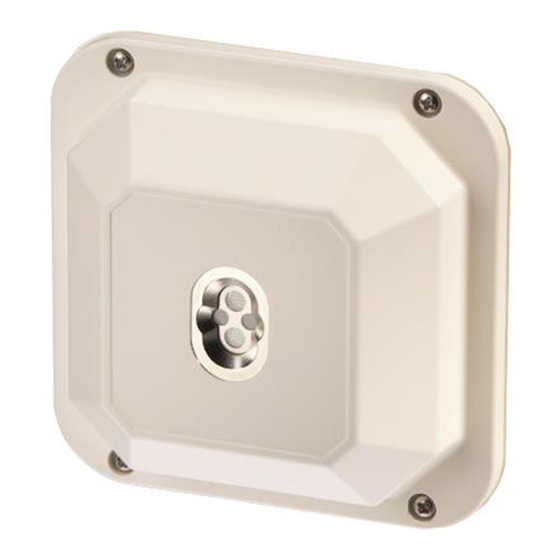
- Page 19 Setup Flame detector The flame detector contains the electronic components and sensory. Flame detector FDF241-9 has three sensors (A, B, C). The alarm indicator (2) displays an alarm. FDF241-9 Figure 3: Front of flame detector with enlarged view of sensors...
- Page 20 Structure and function Setup The connection for the connection cable (2) and the swiveling cover (3) are on the rear of the flame detector. The swiveling cover can be opened to set the parameter set. Figure 4: Rear of flame detector 1 Four screws for mounting 3 Swiveling cover 2 Connection for connection cable...
-
Page 21: Function
Thanks to these characteristics and the three sensors, flame detector FDF241-9 can use ASAtechnology to distinguish between deceptive phenomena and real fires. Flame detector FDF241-9 is suited to use in environments with deceptive phenomena, such as solar radiation or hot motors. -
Page 22: Line Separator
On a loop line, all FDnet/C-NET devices remain fully functional after a single short- circuit. 3.3.2 Selftest Flame detector FDF241-9 regularly carries out a selftest. If a fault is detected, it transmits a message to the control panel. See also... -
Page 23: Messages To The Control Panel
Structure and function Function 3.3.3 Messages to the control panel The flame detector can transmit the following messages to the control panel: FDnet/C-NET operation Message Meaning Measures Danger level '0' Normal condition Danger level '3' The flame detector has detected a fire and transmits an alarm to the control panel. -
Page 24: Accessories
3.4 Accessories 3.4.1 Mounting bracket MV1 For fixing flame detector at 45° Compatible with: – Flame detector FDF241-9 Order number: BPZ:3950450001 3.4.2 Ball and socket joint MWV1 For fixing flame detector at the angle and in the direction required For accurately aligning the flame detector to... -
Page 25: Rain Hood Fdfz241
3.4.4 Rain hood FDFZ241 Rain hood made of plastic For protecting the flame detector during outdoor applications Compatible with: – Flame detector FDF241-9 You will find more information in document A6V10882455 Order number: S54330-N4-A1 3.4.5 LE3 Test lamp For checking flame detectors Compatible with: –... -
Page 26: Micro Terminal Dbz1190-Aa
Structure and function Accessories 3.4.7 Micro terminal DBZ1190-AA Auxiliary terminal for connecting cables For T-branches of additional cabling e.g. for detector heating units, sounder base, external alarm indicators etc. For conductor cross-sections of 0.28…0.5 mm 4-pin Order number: BPZ:4677080001 3.4.8 Connection terminal DBZ1190-AB Auxiliary terminal for connecting cables For T-branches of additional cabling, e.g., for cable shielding, detector heating units,... -
Page 27: Planning
Planning Establish flame detector arrangement 4 Planning In this chapter you will learn how to arrange the flame detector for optimum room monitoring and how you determine the mounting site and appropriate parameter set. Sequence 1. Establish flame detector arrangement [ 2. -
Page 28: Line Of Sight
Planning Establish flame detector arrangement 4.1.1 Line of sight In order for the flame detector to detect a fire, the fire's infrared radiation must reach the flame detector. The infrared radiation can reach the detector through direct or indirect irradiation. Direct irradiation: Indirect irradiation from reflections on walls, equipment etc.: Direct irradiation is many times higher than indirect irradiation. -
Page 29: Arrangement Of Several Flame Detectors
Planning Establish flame detector arrangement 4.1.2 Arrangement of several flame detectors If several flame detectors are needed in a room, they must be arranged such that as high a level of monitoring redundancy as possible is present. In other words, some of the monitoring areas of the individual flame detectors should overlap. -
Page 30: Deceptive Phenomena
Planning Establish flame detector arrangement 4.1.3 Deceptive phenomena When arranging the flame detector, take possible deceptive phenomena into account and take appropriate measures. Deceptive phenomena which may activate the flame detector and trigger a false alarm are listed below. Direct and indirect solar radiation Hot objects, such as hot motors Arc welding Moving parts between the flame detector and a hot object, such as air hoses... -
Page 31: Defining The Place Of Installation
Only use all the calculations provided below for areas with little air circulation. If you want to use the flame detector in areas with high levels of air circulation, please talk to your Siemens contact. See also 2 Calculate detection distance [... -
Page 32: Calculate Detection Distance
Planning Defining the place of installation 4.2.1 Calculate detection distance The maximum detection distance of a flame detector depends on the following factors: Detector sensitivity Fire size Directional sensitivity Fuel Various correction coefficients therefore need to be taken into account when calculating the maximum detection distance. - Page 33 Planning Defining the place of installation Correction coefficient K for directional sensitivity The detection distance depends on the flame detector's vision angle. The following diagram shows the correction coefficients for various vision angles. 45° 40° 30° 20° 10° -10° -20° -30°...
-
Page 34: Calculate Mounting Height
Planning Defining the place of installation Example of how to calculate the maximum detection distance Calculate the maximum detection distance for a heptane fire, 0.1 m in size. The flame detector has a 'Normal' detector sensitivity and a vision angle of 0°. Known: Correction coefficient for detector sensitivity Gg Fire size wanted... -
Page 35: Mask Deceptive Phenomena
Planning Mask deceptive phenomena 4.3 Mask deceptive phenomena If the monitoring area has deceptive phenomena, you can use masks. There are two ways of using masks: Use masks to limit the vision angle of the flame detector such that the detector does not detect the deceptive phenomenon. -
Page 36: Determine Parameter Set
Medium: 6 seconds Very long: 12 seconds The integration time is not the same as the response time. Resistance to deceptive phenomena Flame detector FDF241-9 has parameter sets which take account of the following deceptive phenomena: Direct solar radiation Hot objects... -
Page 37: Parameter Sets For Fdf241-9
Planning Determine parameter set 4.4.1 Parameter sets for FDF241-9 The table below shows the parameter sets for flame detector FDF241-9: Parameter set Sensitivity Integration Resistance to deceptive phenomena Name Solar radiation Arc welding objects Robust Normal (class 2) Very long... - Page 38 Planning Determine parameter set Motor test bed (07) This parameter set is suited to motor test beds. Download 1 (14) and download 2 (15) These application-specific parameter sets can be downloaded locally and depend on the control panel used. 38 | 66 Building Technologies 007011_m_en_-- Fire Safety...
-
Page 39: Mounting / Installation
Mounting / Installation Switch flame detector over to collective operation 5 Mounting / Installation This chapter explains how you install the base for flame detector and how you connect the flame detector to the detector line. Prerequisites The flame detector's mounting site is determined following to the details provided in the 'Planning [ 27]' chapter. - Page 40 Mounting / Installation Switch flame detector over to collective operation 3. Connect the connection cable supplied (1) to the connections (3) in the base for flame detector and on the flame detector. 4. Wait around 15 seconds and then remove the connection cable and source of DC voltage.
-
Page 41: Fit Base For Flame Detector
Mounting / Installation Fit base for flame detector 5.2 Fit base for flame detector WARNING Danger of falling Bodily injury When installing, use a secured ladder or work platform. CAUTION Using the device in a damp and/or corrosive environment Device function is impaired. Use the M20 x 1.5 metal cable gland in damp and/or corrosive environments. - Page 42 Mounting / Installation Fit base for flame detector Figure 16: Mounting of base for flame detector 1 Six openings for cable entry 2 Four screws for installing the base for flame detector Figure 17: Openings for installing base for flame detector 42 | 66 Building Technologies 007011_m_en_--...
-
Page 43: Electrical Connection
Mounting / Installation Electrical connection 5.3 Electrical connection Specialist electrical engineering knowledge is required for installation. Only an expert is permitted to carry out installation work. Incorrect installation can take safety devices out of operation unbeknown to a layperson. The electrical connection depends on the following factors: Connection to an FDnet/C-NET detector line or collective detector line Use of unshielded cables or shielded cables The general process is described below. -
Page 44: Connection To An Addressed Detector Line
Mounting / Installation Electrical connection 5.3.1 Connection to an addressed detector line The following applies to FDnet/C-NET detector lines: Loops, stubs and T-branches are possible. You may only connect external alarm indicators to one detector. Permissible cables for detectors with more than one external alarm indicator according to the collective connection diagram may be migrated to the FDnet/C-NET without any changes. -
Page 45: Use Of Shielded Cables
Mounting / Installation Electrical connection 5.3.1.2 Use of shielded cables The detector line shielding must be connected through in the detector base with auxiliary terminals DBZ1190-xx. There are two ways of connecting external alarm indicators: LINE LINE LINE LINE LINE LINE Figure 19: Connection diagram for addressed detector line with and without external alarm indicators (with shielded cables) -
Page 46: Connection To A Collective Detector Line
Mounting / Installation Electrical connection Variant B 1. Connect the positive pole of the external alarm indicator to the positive pole for the external alarm indicator on the detector. 2. Leave the negative pole for the external alarm indicator on the detector unoccupied. -
Page 47: Use Of Shielded Cables
Mounting / Installation Electrical connection Wire-saving cabling NOTICE Cabling for new sites Wire-saving cabling in external alarm indicators is prohibited for new sites. With wire-saving cabling, the external alarm indicator is connected as follows: The external alarm indicator must be connected to the positive and negative poles of at least one detector (A). - Page 48 Mounting / Installation Electrical connection Variant A 1. Connect the positive pole of the external alarm indicator to the positive pole for the external alarm indicator on the detector. 2. Connect the negative pole of the external alarm indicator to the negative pole for the external alarm indicator on the detector.
-
Page 49: Commissioning
Commissioning Commissioning an addressed detector line 6 Commissioning This chapter explains how you set the parameter set and how you commission the flame detector on the detector line. The commissioning process depends on whether you are using an addressed detector line (FDnet/C-NET) or a collective detector line. - Page 50 Commissioning Commissioning an addressed detector line Figure 22: Mounting of flame detector on base for flame detector 1 Four screws for mounting 3 Bridging connector 2 Connection cable 4 Connection for connection cable 50 | 66 Building Technologies 007011_m_en_-- Fire Safety 2018-06-28...
-
Page 51: Set Parameter Set
Sensitive fast Rapid Motor test bed Download 1 Download 2 Table 3: Parameter sets for FDF241-9 The procedure for setting the parameter set via the control panel is described in the control panel documentation. See also 2 Determine parameter set [ 6.1.3 Run performance check... -
Page 52: Commissioning On A Collective Detector Line
Commissioning Commissioning on a collective detector line 6.2 Commissioning on a collective detector line Sequence 1. Set parameter set [ 2. Install flame detector on base for flame detector [ 3. Run performance check [ You will find information on the individual steps in the specified chapters. 6.2.1 Set parameter set For collective operation, the parameter set is set via the DIP switches in the flame detector. -
Page 53: Install Flame Detector On Base For Flame Detector
Commissioning Commissioning on a collective detector line Parameter set DIP switch FDF241-9 default Robust Universal Universal fast Sensitive Sensitive fast Rapid Motor test bed Table 4: Set parameter set Parameter set no. 00 = parameter set no. 01 See also... -
Page 54: Run Performance Check
Commissioning Commissioning on a collective detector line 1. Remove bridging connector (3) from base for flame detector. 2. Use the connection cable (2) to connect connections (4) in the base for flame detector and on the flame detector. 3. Use four screws (1) to secure the flame detector to the base for flame detector. a The flame detector is fitted. -
Page 55: Maintenance / Repair
Maintenance / Repair Performance check 7 Maintenance / Repair This chapter explains how to run a performance check, what you can do if the flame detector is not functioning correctly and how you can clean the flame detector. 7.1 Performance check Use test lamp LE3 or a test fire to check the function of the flame detector on an annual basis. -
Page 56: Cleaning
Maintenance / Repair Cleaning Performance check with a test fire WARNING Fire hazard from test fire Bodily injury and material damage Only specially trained persons may undertake test fires. These persons must be trained in how to handle fire extinguishers. The size of the test fire depends on the room height. -
Page 57: Repair
Maintenance / Repair Repair 7.3 Repair Problem The flame detector does not activate an alarm during the performance check. Remedy Ensure that the flame detector is registered on the control panel. If the problem persists: Ensure that the protective glass on the flame detector is clean and the sensors are clearly visible. -
Page 58: Specifications
Specifications Technical data 8 Specifications 8.1 Technical data You will find information on approvals, CE marking, and the relevant EU directives for this device (these devices) in the following document(s); see 'Applicable documents' chapter: Document 007012 FDnet/C-NET detector line Operating voltage DC 12…33 V Operating current (quiescent) 0.7 mA... - Page 59 Specifications Technical data Line separator Line voltage: Nominal DC 32 V (= V Minimum DC 12 V (= V Maximum DC 33 V (= V Voltage at which the line separator opens: Minimum DC 7.5 V (= V SO min Maximum DC 10.5 V (= V SO max...
- Page 60 Specifications Technical data Ambient conditions Operating temperature: -35…+70 °C Storage temperature -40…+75 °C Air humidity 95 % rel. Protection category (IEC 60529): IP67 Electromagnetic compatibility: 1 MHz…1 GHz 50 V/m 1 GHz…2 GHz 30 V/m Mechanical data Dimensions (L x W x H) 135 x 135 x 77 mm Weight: Base for flame detector...
-
Page 61: Dimensions
Specifications Dimensions 8.2 Dimensions Base for flame detector FDB291 Base for flame detector FDB291 with flame detector FDF241 9 M20 x 1.5 Mounting bracket MV1 61 | 66 007011_m_en_-- Building Technologies Fire Safety 2018-06-28... - Page 62 Specifications Dimensions Ball and socket joint MWV1 Rain hood DFZ1190 Rain hood FDFZ241 62 | 66 Building Technologies 007011_m_en_-- Fire Safety 2018-06-28...
-
Page 63: Environmental Compatibility And Disposal
Specifications Environmental compatibility and disposal 8.3 Environmental compatibility and disposal This equipment is manufactured using materials and procedures which comply with current environmental protection standards as best as possible. More specifically, the following measures have been undertaken: Use of reusable materials Use of halogen-free plastics Electronic parts and synthetic materials can be separated Larger plastic parts are labeled according to ISO 11469 and... -
Page 64: Index
Index / Index Danger level ............ 23 Accessories Deceptive phenomenon ....21, 30, 32, 35, 36 Ball and socket joint ......15, 24, 41 Arc welding ............30 Mounting bracket ......... 15, 24, 41 Halogen lamp ..........30 Rain hood ..........15, 24, 41 Hot objects ............ - Page 65 Order number ..........16 Message to control panel .........23 Indirect irradiation ..........28 Parameter set ........36, 37, 51, 52 Infrared radiation .........21, 28 FDF241-9 ............37 Installation ............39 Set ............51, 52 Integration time ..........36 Performance check ........... 55 Irradiation ............
- Page 66 Issued by © Siemens Switzerland Ltd, 2003 Siemens Switzerland Ltd Technical specifications and availability subject to change without notice. Building Technologies Division International Headquarters Theilerstrasse 1a CH-6300 Zug +41 58 724 2424 www.siemens.com/buildingtechnologies Document ID: 007011_m_en_-- Manual FD20/FD720 Edition: 2018-06-28...