Sony CFD-G35 Service Manual
Hide thumbs
Also See for CFD-G35:
- Operating instructions (2 pages) ,
- Specifications (2 pages) ,
- Limited warranty (1 page)
Table of Contents
Advertisement
SERVICE MANUAL
Ver 1.4 2002. 11
AUDIO POWER SPECIFICATIONS
POWER OUTPUT AND TOTAL
HARMONIC DISTORTION
With 3.2-ohm loads, both channels driven
from 1 000 - 10 000 Hz; rated 2 W per
channel-minimum RMS power, with no
more than 10 % total harmonic distortion
in AC operation.
Woofer with 4-ohm loads, driven at
50 - 150 Hz; rated 4 W minimum RMS
power, with no more 10 % total harmonic
distortion in AC operation.
Other specifications
CD player section
System
Compact disc digital audio system
Laser diode properties
Material: GaAlAs
Wave length: 780 nm
Emission duration: Continuous
Laser output: Less than 44.6 µW
(This output is the value measured at a distance
of about 200 mm from the objective lens surface
on the optical pick-up block with 7 mm
aperture.)
Spindle speed
200 r/min (rpm) to 500 r/min (rpm)
(CLV)
Number of channels
2
Frequency response
20 - 20 000 Hz +1/–2 dB
Wow and flutter
Below measurable limit
Sony Corporation
9-873-631-05
2002K1600-1
Personal Audio Company
© 2002.11
Published by Sony Engineering Corporation
Model Name Using
Similar Mechanism
CD Mechanism Type
Optical Pick-up Type
Tape Transport Mechanism Type
SPECIFICATIONS
Radio section
Frequency range
FM: 87.5 - 108 MHz
AM: 530 - 1 710 kHz
(US,Canadian,Mexican,Chilean and Peruvian
models)
: 531-1611kHz(Australian model)
: 531-1611kHz(9kHz step)(Singapore model)
: 530-1610kHz(10kHz step)(Argentina model)
Antennas
FM: Telescopic antenna
AM: Built-in ferrite bar antenna
Cassette-corder section
Recording system
4-track 2 channel stereo
Fast winding time
Approx. 115 s (sec.) with Sony cassette C-60
Frequency response
TYPE I (normal): 70 - 13 000 Hz
General
Speaker
Full range: 10 cm (4 in.) dia., 3.2 Ω, cone type
(2)
in.) dia., 4 Ω, cone type (1)
Woofer: 8 cm (3
1
⁄
4
Outputs
Headphones jack (stereo minijack)
For 16 - 68 Ω impedance headphones
Power output
2 W + 2 W (at 3.2 Ω, 10% harmonic distortion
in DC operation)
Woofer:
6 W (at 4 Ω, 10 % harmonic distortion in DC
operation)
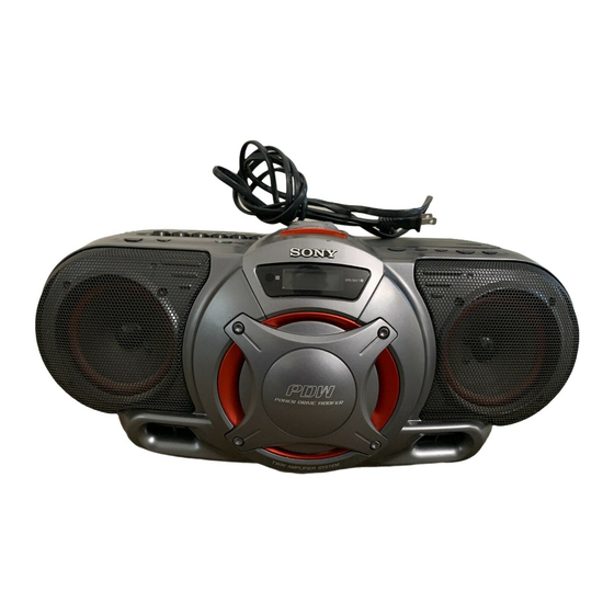
CD RADIO CASSETTE-CORDER
CFD-G35
Canadian Model
Australian Model
CD Section
Tape Section
Power requirements
For CD radio cassette-corder:
120V AC, 60 Hz:
(US,Canadian,Mexican,Chilean and Peruvian
models)
220 – 230V AC, 50 Hz:
(Argentina model)
230V AC, 50 Hz:
(Other models)
9 V DC, 6 size D (R20) batteries
For remote control:
3 V DC, 2 size AA (R6) batteries
Power consumption
AC 25 W
Battery life
For CD radio cassette-corder:
FM recording
Sony R20P: approx. 4 h
Sony alkaline LR20: approx. 19 h
Tape playback
Sony R20P: approx. 1.5 h
Sony alkaline LR20: approx. 7 h
CD playback
Sony R20P: approx. 1.5 h
Sony alkaline LR20: approx. 3.5 h
Dimensions
Approx. 456 × 195 × 330 mm (w/h/d)
(18 × 7
× 13 inches) (incl. projecting parts)
3
⁄
4
Mass
Approx. 6.4 kg (14 lb. 2 oz) (incl. batteries)
Supplied accessory
AC power cord (1)
Remote control (1)
Design and specifications are subject to change
without notice.
US Model
E Model
NEW
CFD-G30
KSM-213RDP
KSS-213R
MF-V5-117
Advertisement
Table of Contents

Related Manuals for Sony CFD-G35


Summary of Contents for Sony CFD-G35
-
Page 1: Specifications
4-track 2 channel stereo CD player section Fast winding time FM recording System Approx. 115 s (sec.) with Sony cassette C-60 Compact disc digital audio system Sony R20P: approx. 4 h Frequency response Laser diode properties Sony alkaline LR20: approx. 19 h... -
Page 2: Table Of Contents
CRITIQUES POUR LA SÉCURITÉ DE FONCTIONNEMENT. NE COMPONENTS WITH SONY PARTS WHOSE PART NUMBERS REMPLACER CES COMPOSANTS QUE PAR DES PIÈSES SONY APPEAR AS SHOWN IN THIS MANUAL OR IN SUPPLEMENTS DONT LES NUMÉROS SONT DONNÉS DANS CE MANUEL OU PUBLISHED BY SONY. -
Page 3: Servicing Notes
CFD-G35 SECTION 1 SERVICING NOTES SAFETY CHECK-OUT NOTES ON HANDLING THE OPTICAL PICK-UP BLOCK OR BASE UNIT After correcting the original service problem, perform the following safety checks before releasing the set to the customer: The laser diode in the optical pick-up block may suffer electrostatic Check the antenna terminals, metal trim, “metallized”... -
Page 4: General
* CD-DA is the abbreviation for Compact TUNE+, – Disc Digital Audio. It is a recording standard used for Audio CDs. .,> If you have any questions or problems concerning your player, please consult your WOOFER nearest Sony dealer. SOUND *The button has a tactile dot. -
Page 5: Disassembly
CFD-G35 SECTION 3 DISASSEMBLY • The equipment can be removed using the following procedure. CABINET (FRONT) ASSY-1 (page 5) CONTROL (POWER), CONTROL (CD), HEADPHONE BOARD CABINET (FRONT) ASSY-2 (page 6) (page 6) PANEL ASSY LCD BOARD, PANEL (UPPER) (page 7) -
Page 6: Cabinet (Front) Assy- 2
CFD-G35 3-2. Cabinet (Front) Assy- 2 flexible flat cable (from MAIN board CNP804) CNP391 Remove the cabinet (front) assy (from PWD board KH353) HEADPHONE board in the direction of the arrow. CNP393 (from L-R/REG board KH374) flexible flat cable (from MAIN board CNP801) MAIN board 3-3. -
Page 7: Panel Assy
CFD-G35 3-4. Panel Assy screw +BVTP 3 × 10 panel assy flexible flat cable (from MAIN board CNP804) dlexible flat cable (from MAIN board CNP801) four screws +BVTP 3 × 10 3-5. LCD Board, Panel (Upper) !™ panel (upper) two screws +BVTP 2.6 ×... -
Page 8: Panel (Upper) Assy- 1
CFD-G35 3-6. Panel (Upper) Assy- 1 Open the cassette holder assy in the direction of the arrow. Open the CD lid in the direction of the arrow. 6 Push STOP/EJECT button. Remove two harnesses in the direction of the arrow. -
Page 9: Power, Trans Board
CFD-G35 3-8. POWER, TRANS Board five screws +BVTP 3 × 10 CNP902 (from BATT board KH951) POWER board, TRANS board 4 two screws +BVTP 3 × 10 power transformer (T901) Remove harnesses in the direction of the arrow. 7 chassis... -
Page 10: Batt Com, Batt Board
CFD-G35 3-10. BATT COM, BATT Board CNP902 (from BATT board KH951) Remove harnesses in the direction of the arrow. BATT board BATT COM board battery terminal battery terminal screw BATT board 3 × 8 (DIA, 10),+WH three screw +BVTP 3 × 10 screw 3 ×... -
Page 11: Main Board- 2
CFD-G35 3-12. MAIN Board- 2 5 MAIN board PDW board L-R/REG board CNP353 CNP374 chassis (CD) 1 from TUNER board CNP1 4 from POWER board CNP903 2 from HEADPHONE board CNP391 3 from HEADPHONE board CNP393 3-13. Mechanism Deck Section (MF-V5-117) -
Page 12: Cd Block Section (Ksm-213Rdp)
CFD-G35 3-14. CD Block Section (KSM-213RDP) Remove solderings flexible flat cable from the four points. (from MAIN board CNP802) CD board flexible flat cable four screws CNP701 2.6 × 10 (DIA, 10),+WH CD block section (KSM-213RDP) 3-15. PDW, L-R/REG Board... -
Page 13: Adjustments
CFD-G35 SECTION 4 ADJUSTMENTS 4-1. Mechanical Adjustments 4-2. Electrical Adjustments TAPE SECTION 0dB = 0.775V PRECAUTION Clean the following parts with a denatured-alcohol-moistened Standard Output Level swab : Output terminal HP OUT record/playback head pinch roller load impedance erase head... - Page 14 CFD-G35 Ver 1.1 2002. 05 0dB = 1 µV TUNER SECTION AM IF ADJUSTMENT Adjust for a maximum reading on level meter. AM Section 450 kHz Function switch : AM no mark : EXCEPT AUS, AR, SP AM RF signal...
- Page 15 CFD-G35 Focus Bias Check CD SECTION Connect an oscilloscope between TP RF and TP VREF on CD board. CD Test Mode Insert the test disc (YEDS-18). • How to put the set into CD test mode Set the CD test mode.
- Page 16 CFD-G35 Adjustment Location : [TUNER BOARD] (Component side) L1: FM Tracking Adjustment CT1: FM Tracking Adjustment L3: AM Tracking Adjustment CNP1 CT3: AM Tracking Adjustment T2: FM IF Adjustment L4: AM Frequency Coverage Adjustment T1: AM IF Adjustment L2: FM Frequency Coverage Adjustment...
-
Page 17: Diagrams
CFD-G35 SECTION 5 Ver 1.3 2002. 09 DIAGRAMS Note on Printed Wiring Boards: Note on Schematic Diagram: 5-1. Circuit Boards Location • X : parts extracted from the component side. • All capacitors are in F unless otherwise noted. p: pF. -
Page 18: Block Diagrams
CFD-G35 Ver 1.3 2002. 09 5-2. Block Diagrams MAIN Section IC301 PRE AMP L OUT TUNER/CD L IN SECTION L-CH IC371 TUNER/CD RADIO IC321 POWER AMP SECTION BUFFER SOUND/VOLUME TAPE R-CH J391 VIN1 OUT1 TAPE STBY Q171 MUTE R-CH VDD(SW) - Page 19 CFD-G35 TUNER/CD Section ANT1 RADIO 6V TELESCOPIC FM IF ANTENNA FRONT-END IF AMP,DET,FM MPX QUAD VCC1 VCC2 MIX OUT FM RF I FM IF RADIO 6V L-CH MAIN FM/AM SECTION MUTE BUFFER R-CH FM RF O AM IF L1, CT1...
-
Page 20: Printed Wiring Board - Tuner Section
CFD-G35 Ver 1.3 2002. 09 5-3. Printed Wiring Board – TUNER Section – • See page 17 for Circuit Boards Location. AUS,AR,SP AUS,AR,SP • Semiconductor Location Ref. No. Location... -
Page 21: Schematic Diagram - Tuner Section
CFD-G35 Ver 1.3 2002. 09 5-4. Schematic Diagram – TUNER Section – • See page 34 for IC Block Diagrams. • See page 17 for Waveforms. US,CND,E,MX C14,C15 0.022:US,CND,E,MX 0.01:AUS,AR,SP AUS,AR,SP... -
Page 22: Printed Wiring Board - Cd Section
CFD-G35 5-5. Printed Wiring Board – CD Section – • See page 17 for Circuit Boards Location. IC702 (LIMIT IN) IC701... -
Page 23: Schematic Diagram - Cd Section
CFD-G35 5-6. Schematic Diagram – CD Section – • See page 34,35 for IC Block Diagrams. • See page 17 for Waveforms. -
Page 24: Printed Wiring Board - Tc Section
CFD-G35 Ver 1.1 2002. 05 5-7. Printed Wiring Board – TC Section – 5-8. Schematic Diagram – TC Section – • See page 17 for Circuit Boards Location. • See page 35 for IC Block Diagrams. • See page 17 for Waveforms. -
Page 25: Printed Wiring Board - Main Section
CFD-G35 Ver 1.3 2002. 09 5-9. Printed Wiring Board – MAIN Section – • See page 17 for Circuit Boards Location. • Semiconductor Location Ref. No. Location D320 D323 D324 D806 D807 CND,AUS,AR,SP D808 D951 D952 D953 D955 D956 CND,AUS,AR,SP... -
Page 26: Schematic Diagram - Main Section (1/2)
CFD-G35 Ver 1.3 2002. 09 5-10. Schematic Diagram – MAIN Section (1/2) – • See page 34 for IC Block Diagrams. BUFFER CND,AUS,AR,SP... -
Page 27: Schematic Diagram - Main Section (2/2)
CFD-G35 Ver 1.3 2002. 09 5-11. Schematic Diagram – MAIN Section (2/2) – • See page 36 for IC Pin Function Description. 0:US,CND,E,MX 470:SP 4.7k:AR 10k:AUS 0:EXCEPT SP 220:SP... -
Page 28: Printed Wiring Board - Amp Section
CFD-G35 Ver 1.3 2002. 09 5-12. Printed Wiring Board – AMP Section – • See page 17 for Circuit Boards Location. AUS,AR,SP AUS,AR,SP C362 US,CND,E,MX C363 AUS,AR,SP US,CND,E,MX IC351 IC371... -
Page 29: Schematic Diagram - Amp Section
CFD-G35 Ver 1.3 2002. 09 5-13. Schematic Diagram – AMP Section – US,CND, C365 E,MX C363 AUS,AR,SP C364 0.1 C362 0.1 AUS,AR,SP... -
Page 30: Printed Wiring Board - Control Section
CFD-G35 5-14. Printed Wiring Board – CONTROL Section – • See page 17 for Circuit Boards Location. POWER SLEEP... -
Page 31: Schematic Diagram - Control Section
CFD-G35 5-15. Schematic Diagram – CONTROL Section –... -
Page 32: Printed Wiring Board - Power Section
CFD-G35 5-16. Printed Wiring Board – POWER Section – • See page 17 for Circuit Boards Location. -
Page 33: Schematic Diagram - Power Section
CFD-G35 Ver 1.3 2002. 09 5-17. Schematic Diagram – POWER Section – C901-904 0.022:US,CND,E,MX 0.1:AUS,AR,SP F902 5A/125V:US,CND,E,MX 3.15A/250V:AUS,AR,SP... - Page 34 CFD-G35 • IC Block Diagrams IC701 LC78646E-E IC1 TA2149BN GND1 FM RF OUT 65 64 63 62 61 80 79 78 77 76 75 74 73 72 71 70 69 68 FM RF VCC1 FM RF IN GATE GATE AM RF IN...
- Page 35 CFD-G35 IC301 TA2068N LOGIC MONITOR MONITOR LINE LINE BUF AMP BUF AMP TAPE TAPE BUF AMP BUF AMP MUTE AMP1 ALC1 ALC2 26dB 26dB AMP1 AMP2 AMP1 AMP2 IC702 BA5826FP-E2 DRIVE DRIVE BUFFER BUFFER LEVEL LEVEL SHIFT SHIFT – –...
-
Page 36: Ic Pin Function Description
CFD-G35 5-18. IC Pin Function Description • IC801 µPD789478GC-8BT System Control (MAIN Board) Pin No. Pin Name Description 1, 2 — Not used (open) VLC2 LCD bias power supply VLC1 LCD bias power supply VLC0 LCD bias power supply 6 to 9... - Page 37 CFD-G35 Pin No. Pin Name Description Main system clock oscillator output (4.19MHz) System reset signal input CD function signal output “L”: active LED CONT LED control signal output (not used) W-LED1 Woofer1 LED control signal output W-LED2 Woofer2 LED control signal output (not used)
-
Page 38: Exploded Views
CFD-G35 SECTION 6 Ver 1.3 2002. 09 EXPLODED VIEWS NOTE: CND : Canadian model. • -XX, -X mean standardized parts, so they may • Color Indication of Appearance Parts Example: E92 : Chilean and Peruvian model. have some differences from the original one. -
Page 39: Cabinet (Rear) Section
CFD-G35 Ver 1.3 2002. 09 6-2. Cabinet (Rear) Section ANT1 cabinet (upper) T901 section supplied F902 supplied supplied Ref. No. Part No. Description Remarks Ref. No. Part No. Description Remarks 3-238-229-01 DUCT (LOWER) (BLACK) 3-238-249-11 HANDLE (SILVER) 3-238-229-11 DUCT (LOWER) (SILVER) -
Page 40: Cabinet (Upper) Section
CFD-G35 Ver 1.3 2002. 09 6-3. Cabinet (Upper) Section S801 mechanism deck section-1 (MF-V5-117) CD mechanism section (KSM-213RDP) supplied S321 supplied supplied supplied Ref. No. Part No. Description Remarks Ref. No. Part No. Description Remarks * 101 A-3178-395-A L-R/REG BOARD, COMPLETE 3-931-379-21 RUBBER, VIBRATION PROOF 3-238-232-01 CHASSIS (HS.L) -
Page 41: Mechanism Deck Section- 1 (Mf-V5-117)
CFD-G35 6-4. Mechanism Deck Section- 1 (MF-V5-117) HRP301 HE301 mechanism deck section-2 (MF-V5-117) Ref. No. Part No. Description Remarks Ref. No. Part No. Description Remarks 3-933-010-01 SPRING (S/P), TORSION * 162 3-008-587-01 SLIDER (STOP) 3-933-025-01 SPRING (P), TORSION * 163... -
Page 42: Mechanism Deck Section- 2 (Mf-V5-117)
CFD-G35 6-5. Mechanism Deck Section- 2 (MF-V5-117) S322 M321 Ref. No. Part No. Description Remarks Ref. No. Part No. Description Remarks 3-933-029-01 LEVER, ERASING PREVENTION 3-932-993-01 CHASSIS, OUTSERT 3-933-182-01 SPRING, CASSETTE 3-343-358-01 RING, RETAINING 3-932-995-01 GEAR (MID) 3-933-005-01 SPRING (CAM), COMPRESSION... -
Page 43: Cd Mechanism Section (Ksm-213Rdp)
CFD-G35 Ver 1.3 2002. 09 6-6. CD Mechanism Section (KSM-213RDP) (including M702) M702 M701 Ref. No. Part No. Description Remarks Ref. No. Part No. Description Remarks 0 251 8-820-161-02 OPTICAL PICK-UP KSS-213R 3-713-786-51 SCREW (M2 x 3) * 252 2-169-065-01 GEAR (A) -
Page 44: Electrical Parts List
CFD-G35 SECTION 7 Ver 1.3 2002. 09 ELECTRICAL PARTS LIST BATT BATT COM NOTE: • Due to standardization, replacements in the • Items marked “*” are not stocked since they CND : Canadian model. E92 : Chilean and Peruvian model. - Page 45 CFD-G35 Ver 1.1 2002. 05 CONTROL (CD) CONTROL (POWER) CONTROL (VOL) Ref. No. Part No. Description Remarks Ref. No. Part No. Description Remarks R706 1-216-841-11 METAL CHIP 1/16W 1-684-458-11 CONTROL (POWER) BOARD R707 1-216-797-11 METAL CHIP 1/16W *********************** R708 1-216-833-11 METAL CHIP...
- Page 46 CFD-G35 Ver 1.3 2002. 09 HEADPHONE L-R/REG MAIN Ref. No. Part No. Description Remarks Ref. No. Part No. Description Remarks 1-684-457-11 HEADPHONE BOARD < RESISTOR > ***************** R171 1-216-841-11 METAL CHIP 1/16W < CONNECTOR > R172 1-216-837-11 METAL CHIP 1/16W...
- Page 47 CFD-G35 Ver 1.3 2002. 09 MAIN Ref. No. Part No. Description Remarks Ref. No. Part No. Description Remarks C127 1-162-966-11 CERAMIC CHIP 0.0022uF 10% C841 1-162-927-11 CERAMIC CHIP 100PF C129 1-107-826-11 CERAMIC CHIP 0.1uF 10.00% 16V C846 1-107-826-11 CERAMIC CHIP 0.1uF...
- Page 48 CFD-G35 Ver 1.3 2002. 09 MAIN Ref. No. Part No. Description Remarks Ref. No. Part No. Description Remarks < TRANSISTOR > R813 1-216-821-11 METAL CHIP 1/16W R814 1-216-821-11 METAL CHIP 1/16W Q321 8-729-281-53 TRANSISTOR 2SC1815GR-TPE2 R815 1-216-809-11 METAL CHIP 1/16W...
- Page 49 CFD-G35 Ver 1.3 2002. 09 MAIN POWER Ref. No. Part No. Description Remarks Ref. No. Part No. Description Remarks R961 1-216-821-11 METAL CHIP 1/16W < RESISTOR > (CND,AUS,AR,SP) R964 1-216-809-11 METAL CHIP 1/16W R351 1-216-829-11 METAL CHIP 4.7K 1/16W R965...
- Page 50 CFD-G35 Ver 1.3 2002. 09 TRANS TUNER Ref. No. Part No. Description Remarks Ref. No. Part No. Description Remarks C102 1-104-665-11 ELECT 100uF 20.00% 10V R302 1-216-829-11 METAL CHIP 4.7K 1/16W C103 1-165-176-11 CERAMIC CHIP 0.047uF 10.00% 16V C104 1-162-966-11 CERAMIC CHIP 0.0022uF 10%...
- Page 51 CFD-G35 Ver 1.1 2002. 05 TUNER Ref. No. Part No. Description Remarks Ref. No. Part No. Description Remarks 1-107-826-11 CERAMIC CHIP 0.1uF 10.00% 16V < IC > 1-126-960-11 ELECT 20.00% 50V 1-162-960-11 CERAMIC CHIP 220PF 6-700-512-01 IC TA2149BN 1-162-927-11 CERAMIC CHIP...
- Page 52 CFD-G35 Ver 1.4 2002. 11 TUNER Ref. No. Part No. Description Remarks Ref. No. Part No. Description Remarks < TRANSFORMER > SP391 1-825-029-11 SPEAKER (10cm)(BLACK) SP391 1-825-159-11 SPEAKER (10cm)(SILVER) 1-433-741-11 TRANSFORMER, IF SP392 1-825-029-11 SPEAKER (10cm)(BLACK) 1-419-465-11 COIL (DET) SP392...
- Page 53 CFD-G35 MEMO...
- Page 54 CFD-G35 REVISION HISTORY Clicking the version allows you to jump to the revised page. Also, clicking the version at the upper right on the revised page allows you to jump to the next revised page. Ver. Date Description of Revision 2002.03...