Table of Contents
Advertisement
SERVICE MANUAL
Ver 1.0 2004. 07
CD player section
System
Compact disc digital audio system
Laser diode properties
Material: GaAlAs
Wave length: 780 nm
Emission duration: Continuous
Laser output: Less than 44.6 µW
(This output is the value measured at a distance of
about 200 mm from the objective lens surface on the
optical pick-up block with 7 mm aperture.)
Spindle speed
200 r/min (rpm) to 500 r/min (rpm) (CLV)
Number of channels
2
Frequency response
20 - 20 000 Hz +1/–2 dB
Wow and flutter
Below measurable limit
Radio section
Frequency range
Mexican model
FM
87.5 - 108 MHz
AM
530 - 1 710 kHz
Other models
FM
87.5 - 108 MHz
AM
531 - 1 611 kHz (9 kHz step)
530 - 1 610 kHz (10 kHz step)
Antennas
FM: Telescopic antenna
AM: Built-in ferrite bar antenna
Sony Corporation
9-879-113-01
2004G04-1
Personal Audio Company
© 2004. 07
Published by Sony Engineering Corporation
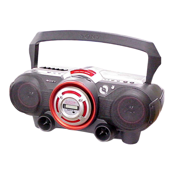
CFD-G550CP
Model Name Using Similar Mechanism CFD-G500
CD
CD Mechanism Type
Section
Optical Pick-up Name
Model Name Using Similar Mechanism CFD-G500
TC
Section Tape Transport Mechanism Type
SPECIFICATIONS
Cassette-corder section
Recording system
4-track 2 channel stereo
Fast winding time
Approx. 120 s (sec.) with Sony cassette C-60
Frequency response
TYPE I (normal): 70 - 13 000 Hz
General
Speaker
Full range: 10 cm dia., 3.2 Ω, cone type (2)
Woofer: 10 cm (4 in.) dia., 4 Ω, cone type (1)
Outputs
Headphones jack (stereo minijack)
For 16 - 68 Ω impedance headphones
Power output
4 W + 4 W (at 3.2 Ω, 10% harmonic distortion
in DC operation)
Woofer:
12 W (at 4 Ω, 10 % harmonic distortion in DC
operation)
CD RADIO CASSETTE-CORDER
E Model
KSM-213RDP
KSS-213R
MF-G500
– Continued on next page –
1
Advertisement
Table of Contents

Related Manuals for Sony CFD-G550CP


Summary of Contents for Sony CFD-G550CP
- Page 1 Compact disc digital audio system 4-track 2 channel stereo Laser diode properties Fast winding time Material: GaAlAs Approx. 120 s (sec.) with Sony cassette C-60 Wave length: 780 nm Frequency response Emission duration: Continuous TYPE I (normal): 70 - 13 000 Hz Laser output: Less than 44.6 µW...
- Page 2 COMPONENTS IDENTIFIED BY MARK 0 OR DOTTED LINE WITH MARK 0 ON THE SCHEMATIC DIAGRAMS AND IN THE PARTS LIST ARE CRITICAL TO SAFE OPERATION. REPLACE THESE COMPONENTS WITH SONY PARTS WHOSE PART NUMBERS APPEAR AS SHOWN IN THIS MANUAL OR IN SUPPLEMENTS PUBLISHED BY SONY.
-
Page 3: Table Of Contents
CFD-G550CP • UNLEADED SOLDER TABLE OF CONTENTS Boards requiring use of unleaded solder are printed with the lead- free mark (LF) indicating the solder contains no lead. 1. SERVICING NOTES ............4 (Caution: Some printed circuit boards may not come printed with the lead free mark due to their particular size.) -
Page 4: Servicing Notes
CFD-G550CP SECTION 1 SERVICING NOTES LASER DIODE AND FOCUS SEARCH OPERATION CHUCK PLATE JIG ON REPAIRING CHECK 1. Turn ON the [OPERATE] button and press [CD] button to CD On repairing CD section, playing a disc without the lid (CD), use position. -
Page 5: General
CFD-G550CP SECTION 2 GENERAL This section is extracted from instruction manual. Basic Operations Playing an audio CD or MP3 files Press u (N on the remote). Display 2, 3 The player plays all the tracks once. To play a CD with MP3 files, see page 6. -
Page 6: Listening To The Radio
CFD-G550CP Listening to the radio Use these buttons for additional operations POWER VOL +, – MODE Press If the FM broadcast is adjust the volume VOL +*, – noisy, press MODE until Connect the supplied AC power cord (see page 23). -
Page 7: Recording On A Tape
CFD-G550CP Recording on a tape Press z to start recording (N is depressed automatically). Use these buttons for additional operations Connect the supplied AC power cord (see page 23). POWER Press POWER to turn on the player. Press xZ to open the tape... -
Page 8: Disassembly
CFD-G550CP SECTION 3 DISASSEMBLY • The equipment can be removed using the following procedure. 3-1. CABINET (UPPER) (1) SECTION (Page 9) 3-2. CABINET (UPPER) (2) SECTION (Page 9) 3-3. CABINET (FRONT) SECTION 3-7. CONTROL 1 BOARD (Page 10) (Page 12) 3-4. -
Page 9: Cabinet (Upper) (1) Section
CFD-G550CP Note : Follow the disassembly procedure in the numerical order given. 3-1. CABINET (UPPER) (1) SECTION Open the handle in the 4 two screws direction of the arrow. BV tapping (B3) 6 two screws 2 seven screws BV tapping (B3) BV tapping (B3) Open the cassette lid. -
Page 10: Cabinet (Front) Section
CFD-G550CP 3-3. CABINET (FRONT) SECTION 4 four screws BV tapping (B3) 3 four screws BV tapping (B3) cabinet (front) section 2 four screws BV tapping (B3) battery lid 3-4. CONTROL 2 BOARD, VOL BOARD 2 button (function) 6 two screws BV tapping (B2.6) -
Page 11: Lcd Board
CFD-G550CP 3-5. LCD BOARD 9 panel LCD sub assy qa ring ornament 0 plate light guide LED LCD board 5 four screws BV tapping (B2.6) 4 five screws 7 three screws BV tapping (B3) BV tapping (B2.6) woofer speaker 6 rear cover... -
Page 12: Control 1 Board
CFD-G550CP 3-7. CONTROL 1 BOARD 3 two screws 2 nine screws PWH tapping (B2.6) BV tapping (B2.6) 5 screw BV tapping (B2.6) 4 CONTROL 1 board 1 CNP806 (3P) 6 button (woofer) assy 7 button (CD) 8 button (power) 3-8. H/P BOARD, TU BOARD... -
Page 13: Main Board
CFD-G550CP 3-9. MAIN BOARD 5 two screws BV tapping (B3) 8 MAIN board connector (2P) CNP303 (6P) 7 CNJ806 (20P) CNP806 (3P) CNP805 (11P) 3-10. CD BLOCK SECTION 1 two screws PWH tapping (B2.6) 1 two screws PWH tapping (B2.6) -
Page 14: Optical Pick-Up
CFD-G550CP 3-11. OPTICAL PICK-UP 6 optical pick-up 5 sled shaft claw 1 gear (A) 2 screw +P 2x 3 3 screw +P 2x 3 3-12. TAPE MECHANISM DECK 1 CNP303 (6P) 3 three screws BV tapping (B3) 5 tape mechanism deck 2 CN303 (11P) Open the cassette lid. -
Page 15: Tc Board
CFD-G550CP 3-13. TC BOARD 1 screw 4 TC board Remove soldering from the four points. yellow red white black TC board 2 hook 3-14. MAIN BELT, SUB BELT 1 two screws ( +bind DT M2 x 6) 3 motor assy... -
Page 16: Mechanical Adjustments
CFD-G550CP SECTION 4 SECTION 5 MECHANICAL ADJUSTMENTS ELECTRICAL ADJUSTMENTS PRECAUTION TAPE SECTION 0 dB = 0.775 V 1. Clean the following parts with a denatured-alcohol-moistened swab : • Standard Output Level record/playback head pinch roller Output terminal HP OUT erase head rubber belts 32 Ω... -
Page 17: Tuner Section
CFD-G550CP TUNER SECTION 0 dB = 1 µV AM IF ADJUSTMENT • AM Section Adjust for a maximum reading on level meter. Setting: RADIO BAND•AUTO PRESET button: AM 450 kHz AM RF signal generator AM FREQUENCY COVERAGE Put the lead-wire... -
Page 18: Cd Section
CFD-G550CP Adjustment Location: CT3, L3 TRACKING ADJUSTMENT – MAIN board (component side) – TP (VT) (CONDUCTOR SIDE) CT1, L1 TP (FM IN) TRACKING (CONDUCTOR SIDE) ADJUSTMENT ADJUSTMENT FREQUENCY COVERAGE ADJUSTMENT ADJUSTMENT FREQUENCY COVERAGE ADJUSTMENT CD SECTION CD section adjustments are done automatically in this set. -
Page 19: Diagrams
CFD-G550CP SECTION 6 DIAGRAMS 6-1. BLOCK DIAGRAM — CD SECTION — LCHO CD L CH INTERPOLATION SLICE ERROR MUTE DIGITAL FIN2 EFMIN LEVEL CORRECTION (Page 20) & FILTER CONTROL AUDIO CD ATTENUATION & RCHO R-CH DEEMPHASIS 1-bit DAC PH/BH DATA... -
Page 20: Block Diagram - Main Section
CFD-G550CP 6-2. BLOCK DIAGRAM — MAIN SECTION — OVER LOAD WOOFER AMP IC351 Q351 WOOFER SP393 CONTROL WOOFER R.RO Q321-323 R.IN MUTE IC321 R.LINE REC/PB Q354 CD_IN_R ELECTRONIC VOLUME PRE AMP STANDBY (Page 19) IC301 L.RO ALC 2 Q352,353 POWER AMP L.LINE... -
Page 21: Note For Printed Wiring Boards And Schematic Diagrams
CFD-G550CP 6-3. NOTE FOR PRINTED WIRING BOARDS AND SCHEMATIC DIAGRAMS 6-5. CIRCUIT BOARDS LOCATION THIS NOTE IS COMMON FOR PRINTED WIRING BOARDS AND SCHEMATIC DIAGRAMS. (In addition to this, the necessary note is printed in each block.) POWER board CONTROL 2 board... -
Page 22: Printed Wiring Board - Cd Section
CFD-G550CP 6-6. PRINTED WIRING BOARD — CD SECTION — • Refer to page 21 for Circuit Boards Location. : Uses unleaded solder. (Page 28) IC1001 IC701 • Semiconductor Location Ref. No. Location IC701 F-10 IC702 IC1001 D-12 IC1002 D-13 IC1003... -
Page 23: Schematic Diagram - Cd Section
CFD-G550CP 6-7. SCHEMATIC DIAGRAM — CD SECTION — • Refer to page 21 for Waveforms. • Refer to page 35 for IC Block Diagrams. • Refer to page 38 for IC Pin Descriptions of IC1001. C754 C709 R731 R728 R727... -
Page 24: Printed Wiring Board - Tuner Section
CFD-G550CP 6-8. PRINTED WIRING BOARD — TUNER SECTION — • Refer to page 21 for Circuit Boards Location. : Uses unleaded solder. KH801 (Page 28) KH802 (Page 28) 1-688-455- (11) • Semiconductor Location Ref. No. Location C-10 C-12 C-12 E-10... -
Page 25: Schematic Diagram - Tuner Section
CFD-G550CP 6-9. SCHEMATIC DIAGRAM — TUNER SECTION — • Refer to page 21 for Waveforms. • Refer to page 36 for IC Block Diagrams. JC12 JC11 JC24 IC B/D IC B/D JC13 ANT1 CNP2 CNP1 (Page 27) JC33 JC34 (Page 27) -
Page 26: Schematic Diagram - Main Section (1/2)
CFD-G550CP 6-10. SCHEMATIC DIAGRAM — MAIN SECTION (1/2) — • Refer to page 37 for IC Block Diagrams. IC351 R364 R365 D352 C360 R225 R125 R226 R126 R362 Q351 C131 R353 C356 R351 R361 C359 C231 C355 Q354 C323 R357... -
Page 27: Schematic Diagram - Main Section (2/2)
CFD-G550CP 6-11. SCHEMATIC DIAGRAM — MAIN SECTION (2/2) — • Refer to page 40 for IC Pin Descriptions of IC801. R881 C824 R887 C825 D801 JC891 C826 R884 R885 R886 R829 Q806 C827 L806 C828 R897 IC803 C823 R888 C857... -
Page 28: Printed Wiring Boards - Main Section
CFD-G550CP 6-12. PRINTED WIRING BOARDS — MAIN SECTION — • Refer to page 21 for Circuit Boards Location. : Uses unleaded solder. (Page 32) (Page 32) (Page 32) CONTROL 1 BOARD BOARD CONTROL 2 CN801 KH401 BOARD • Semiconductor Location Ref. -
Page 29: Printed Wiring Board - Tc Section
CFD-G550CP 6-13. PRINTED WIRING BOARD — TC SECTION — • Refer to page 21 for Circuit Boards Location. : Uses unleaded solder. T301 C307 C305 R307 R308 C304 R306 C306 IC301 JC304 CN303 R302 R206 R202 R303 S301 S301 (REC/PB) -
Page 30: Schematic Diagram - Tc Section
CFD-G550CP 6-14. SCHEMATIC DIAGRAM — TC SECTION — • Refer to page 37 for IC Block Diagrams. IC301 R103 R112 IC B/D R301 C102 R102 C103 R104 R111 C301 C104 C101 JC302 C107 R110 R101 C105 JC306 JC305 C303 C302... -
Page 31: Schematic Diagram - Control Section
CFD-G550CP 6-15. SCHEMATIC DIAGRAM — CONTROL SECTION — IC891 LCD401 D402 R427 CN801 R469 R452 R442 C401 R470 R428 R475 L401 R443 C404 C406 R444 C403 (Page 27) C405 C407 R445 C408 R446 IC401 R448 R449 R450 R447 R451 C413... -
Page 32: Printed Wiring Boards - Control Section
CFD-G550CP 6-16. PRINTED WIRING BOARDS — CONTROL SECTION — • Refer to page 21 for Circuit Boards Location. : Uses unleaded solder. S404 S405 S401 S402 S406 S403 S408 S407 S418 S417 R408 R409 R404 R405 R401 R402 R403 R424... -
Page 33: Printed Wiring Boards - Power Section
CFD-G550CP 6-17. PRINTED WIRING BOARDS — POWER SECTION — • Refer to page 21 for Circuit Boards Location. : Uses unleaded solder. CNJ901 AC IN MAIN BOARD CNP301 (Page 28) DRY BATTERY SIE "D" 1-863-313- (IEC DESIGNATION R20) 8PCS,12V T901... -
Page 34: Schematic Diagram - Power Section
CFD-G550CP 6-18. SCHEMATIC DIAGRAM — POWER SECTION — KH903 C909 C901 (Page 26) D901 D902 C902 T901 CNJ901 JW904 C903 JW919 CNP902 JW903 F902 JW918 D903 JW953 JW954 D904 JW944 JW943 JW912 KH941 JW905 C904 JW951 JW952 JW941 JW911 JW906... -
Page 35: Ic Block Diagrams
CFD-G550CP • IC BLOCK DIAGRAMS IC701 LC78646E-US-E (CD/MP3 Board) 78 77 76 75 74 73 72 71 69 68 67 66 65 64 63 62 61 FIN1 – FIN2 – TIN1 TBAL – – TIN2 – – TBAL – RFMON... - Page 36 CFD-G550CP IC702 BA5826FP-E2 (CD/MP3 Board) IC1 TA2149BN (TU Board) GND1 FM RF-OUT FM RF SP– D.BUFF VCC1 FM RF-IN SL– AM RF-IN D.BUFF AM LOW CUT LEVEL D.BUFF SHIFT MIX OUT FM OSC D.BUFF SPIN LEVEL SHIFT AM OSC BUFF...
- Page 37 CFD-G550CP IC321 BD3870FS-E2 (MAIN Board (1/2)) Treble1 Treble2 Bass2 Bass1 Logic fc=8kHz fc=8kHz fo=80Hz fo=80Hz Vcc/2 Vcc/2 0dB- -87dB Vcc/2 Vcc/2 Vcc/2 IC301 TA2068N (TC Board) LINE L.LIN L.PO MIC I/EX AMP1 BUF AMP TAPE L.NF RADIO L.RAD AMP1 L.RO...
- Page 38 CFD-G550CP • IC PIN DESCRIPTIONS • IC1001 LC78684E-US-E (MP3 DECODER, CD-ROM DECODER, ANTI-SHOCK CONTROLLER) (CD/MP3 BOARD) Pin No. Pin Name Pin Description LRSY CD L/R clock input ADDATA Audio data output ADBCK Audio bit clock output ADLRCK Audio L/R clock output...
- Page 39 CFD-G550CP Pin No. Pin Name Pin Description Data connecting point detection completion flag output (at CD-DA, H: active)/DRAM CNTOK data serial output (at CD-ROM, H: active) (Not used. (Open)) DRAM write discontinue flag output (at CD-DA, H: active)/DRAM data transfer clock output (at CD-ROM, H: active) (Not used.
- Page 40 CFD-G550CP • IC801 µPD784216AGF-546-3BA (SYSTEM CONTROL) (MAIN BOARD (2/2)) Pin No. Pin Name Pin Description TU CE PLL IC chip enable output TU DATA PLL IC data output TU CLK PLL IC clock output TU COUNT PLL IC IF count data result input TU MUTE Tuner IF request &...
- Page 41 CFD-G550CP Pin No. Pin Name Pin Description Not used REG CHK Regulator check detect signal input 59, 60 Not used AVSS — Ground 62, 63 Ground AVREF1 — Power supply pin (+3.3V) Not used 66, 67 Not used CMDOUT (MP3)
-
Page 42: Exploded Views
CFD-G550CP SECTION 7 EXPLODED VIEWS NOTE: • The mechanical parts with no reference • Color Indication of Appearance Parts The components identified by mark 0 or dotted line with mark number in the exploded views are not supplied. Example : 0 are critical for safety. -
Page 43: Cabinet (Front) Section
CFD-G550CP 7-2. CABINET (FRONT) SECTION LCD401 Ref. No. Part No. Description Remark Ref. No. Part No. Description Remark X-3385-172-1 PANEL (LCD) SUB ASSY A-1068-193-A VOL BOARD, COMPLETE 3-264-881-01 RING (ORNAMENT) 3-264-885-11 BUTTON (FUNCTION) 3-264-882-02 LIGHT GUIDE PLATE, LED A-1068-195-A CONTROL 2 BOARD, COMPLETE A-1068-190-A LCD BOARD, COMPLETE 3-254-151-01 SCREW (B2.6), (+) P TAPPING... -
Page 44: Cabinet (Rear) Section
CFD-G550CP 7-3. CABINET (REAR) SECTION T901 F902 not supplied (BAT2 board) not supplied (BAT1 board) The components identified by mark 0 or dotted line with mark. 0 are critical for safety. Replace only with part number specified. Ref. No. Part No. -
Page 45: Cabinet (Upper) (1) Section
CFD-G550CP 7-4. CABINET (UPPER) (1) SECTION ANT1 cabinet (upper) S801 section-2 supplied (JACK HOLD board) Ref. No. Part No. Description Remark Ref. No. Part No. Description Remark 3-252-828-01 SCREW (B2.6), (+) PWH TAPPING 3-019-395-01 PLATE, CHUCKING A-1068-199-A H/P BOARD, COMPLETE... -
Page 46: Cabinet (Upper) (2) Section
CFD-G550CP 7-5. CABINET (UPPER) (2) SECTION not supplied IC351 not supplied (CD/MP3 board) Q972 not supplied Q971 IC371 tape mechanism deck section CD mechanism section Ref. No. Part No. Description Remark Ref. No. Part No. Description Remark 3-264-890-01 BUTTON (PAUSE) -
Page 47: Tape Mechanism Section
CFD-G550CP 7-6. TAPE MECHANISM SECTION M801 not supplied not supplied HRP301 Ref. No. Part No. Description Remark Ref. No. Part No. Description Remark A-3172-207-A MF-G500//C * 257 A-4547-315-A TC BOARD, COMPLETE 3-244-079-01 BELT (B), SUB 3-237-719-02 CHASSIS, TC 3-244-080-01 BELT (B), MAIN... -
Page 48: Cd Mechanism Section
CFD-G550CP 7-7. CD MECHANISM SECTION (KSM-213RDP) (including M701) M702 The components identified by mark 0 or dotted line with mark. 0 are critical for safety. Replace only with part number specified. Ref. No. Part No. Description Remark Ref. No. Part No. -
Page 49: Electrical Parts List
CFD-G550CP SECTION 8 BAT1 BAT2 CD/MP3 ELECTRICAL PARTS LIST NOTE: • Due to standardization, replacements in • Items marked “*” are not stocked since The components identified by mark 0 or dotted line with mark. the parts list may be different from the they are seldom required for routine service. - Page 50 CFD-G550CP CD/MP3 CONTROL 1 Ref. No. Part No. Description Remark Ref. No. Part No. Description Remark C1074 1-162-919-11 CERAMIC CHIP 22PF R730 1-216-821-11 METAL CHIP 1/10W C1110 1-162-970-11 CERAMIC CHIP 0.01uF R731 1-216-825-11 METAL CHIP 2.2K 1/10W R732 1-216-809-11 METAL CHIP 1/10W <...
- Page 51 CFD-G550CP CONTROL 1 CONTROL 2 Ref. No. Part No. Description Remark Ref. No. Part No. Description Remark R406 1-216-825-11 METAL CHIP 2.2K 1/10W A-1068-190-A LCD BOARD, COMPLETE R407 1-216-821-11 METAL CHIP 1/10W ******************** R408 1-216-829-11 METAL CHIP 4.7K 1/10W R409 1-216-825-11 METAL CHIP 2.2K...
- Page 52 CFD-G550CP MAIN Ref. No. Part No. Description Remark Ref. No. Part No. Description Remark R452 1-216-845-11 METAL CHIP 100K 1/10W C321 1-162-962-11 CERAMIC CHIP 470PF R467 1-216-809-11 METAL CHIP 1/10W C322 1-162-964-11 CERAMIC CHIP 0.001uF R468 1-216-809-11 METAL CHIP 1/10W...
- Page 53 CFD-G550CP MAIN Ref. No. Part No. Description Remark Ref. No. Part No. Description Remark C840 1-162-927-11 CERAMIC CHIP 100PF D953 8-719-988-61 DIODE 1SS355TE-17 (E41) C841 1-162-964-11 CERAMIC CHIP 0.001uF D954 8-719-977-28 DIODE DTZ10B C842 1-162-964-11 CERAMIC CHIP 0.001uF D955 8-719-978-33 DIODE DTZ-TT11-6.8B...
- Page 54 CFD-G550CP MAIN Ref. No. Part No. Description Remark Ref. No. Part No. Description Remark < RESISTOR > R364 1-216-857-11 METAL CHIP 1/10W R365 1-216-857-11 METAL CHIP 1/10W R123 1-216-829-11 METAL CHIP 4.7K 1/10W R366 1-216-833-11 METAL CHIP 1/10W R124 1-216-825-11 METAL CHIP 2.2K...
- Page 55 CFD-G550CP MAIN POWER Ref. No. Part No. Description Remark Ref. No. Part No. Description Remark R860 1-216-821-11 METAL CHIP 1/10W < VIBRATOR > R861 1-216-809-11 METAL CHIP 1/10W R862 1-216-809-11 METAL CHIP 1/10W X801 1-795-526-12 VIBRATOR, CERAMIC (5MHz) R863 1-216-821-11 METAL CHIP...
- Page 56 CFD-G550CP TRANS Ref. No. Part No. Description Remark Ref. No. Part No. Description Remark C304 1-126-947-11 ELECT 47uF < TRANSFORMER > C305 1-162-962-11 CERAMIC CHIP 470PF C306 1-162-970-11 CERAMIC CHIP 0.01uF T301 1-416-041-11 TRANSFORMER, BIAS OSCILLATION C307 1-162-964-11 CERAMIC CHIP 0.001uF...
- Page 57 CFD-G550CP Ref. No. Part No. Description Remark Ref. No. Part No. Description Remark 1-164-230-11 CERAMIC CHIP 220PF JC13 1-216-864-11 SHORT CHIP 1-162-927-11 CERAMIC CHIP 100PF JC24 1-216-864-11 SHORT CHIP 0 (E41) 1-162-919-11 CERAMIC CHIP 22PF JC33 1-216-864-11 SHORT CHIP 1-162-915-11 CERAMIC CHIP 10PF 0.5PF...
- Page 58 CFD-G550CP Ref. No. Part No. Description Remark R419 1-216-825-11 METAL CHIP 2.2K 1/10W R420 1-216-837-11 METAL CHIP 1/10W < SWITCH > S414 1-786-050-21 SWITCH, KEYBOARD (VOL –) S415 1-786-050-21 SWITCH, KEYBOARD (VOL +) S416 1-786-050-21 SWITCH, KEYBOARD (SOUND) ************************************************************* MISCELLANEOUS...
- Page 59 CFD-G550CP MEMO...
- Page 60 CFD-G550CP REVISION HISTORY Clicking the version allows you to jump to the revised page. Also, clicking the version at the upper on the revised page allows you to jump to the next revised page. Ver. Date Description of Revision 2004. 07...