Table of Contents
Advertisement
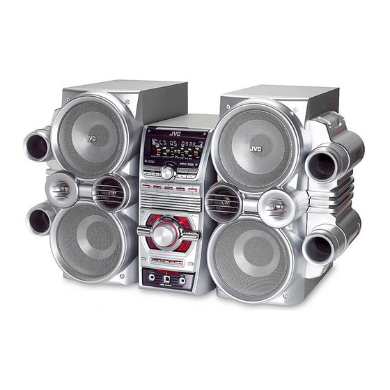
SERVICE MANUAL
COMPACT COMPONENT SYSYTEM
6
2005
MB366
Lead free solder used in the board (material : Sn-Ag-Cu, melting point : 219 Centigrade)
1
PRECAUTION. . . . . . . . . . . . . . . . . . . . . . . . . . . . . . . . . . . . . . . . . . . . . . . . . . . . . . . . . . . . . . . . . . . . . . . . . 1-3
2
SPECIFIC SERVICE INSTRUCTIONS . . . . . . . . . . . . . . . . . . . . . . . . . . . . . . . . . . . . . . . . . . . . . . . . . . . . . . 1-5
3
DISASSEMBLY . . . . . . . . . . . . . . . . . . . . . . . . . . . . . . . . . . . . . . . . . . . . . . . . . . . . . . . . . . . . . . . . . . . . . . . 1-6
4
ADJUSTMENT . . . . . . . . . . . . . . . . . . . . . . . . . . . . . . . . . . . . . . . . . . . . . . . . . . . . . . . . . . . . . . . . . . . . . . . 1-21
5
TROUBLESHOOTING . . . . . . . . . . . . . . . . . . . . . . . . . . . . . . . . . . . . . . . . . . . . . . . . . . . . . . . . . . . . . . . . . 1-21
HX-C6
SP-HXC6
CA-HXC6
TABLE OF CONTENTS
COPYRIGHT © 2005 Victor Company of Japan, Limited
Area suffix
J ---------------------------- U.S.A.
SP-HXC6
No.MB366
2005/6
Advertisement
Chapters
Table of Contents

Related Manuals for JVC HX-C6


Summary of Contents for JVC HX-C6
-
Page 1: Table Of Contents
SERVICE MANUAL COMPACT COMPONENT SYSYTEM MB366 2005 HX-C6 Area suffix J ---------------------------- U.S.A. SP-HXC6 CA-HXC6 SP-HXC6 Lead free solder used in the board (material : Sn-Ag-Cu, melting point : 219 Centigrade) TABLE OF CONTENTS PRECAUTION............... . . 1-3 SPECIFIC SERVICE INSTRUCTIONS . - Page 2 SPECIFICATION Amplifier section-CA-HXC6 Output Power SUB WOOFER 170 W per channel, min. RMS, driven into 6 at 63 Hz with no more than 10% total harmonic distortion. MAIN SPEAKER 80 W per channel, min. RMS, driven into 4 at 1 kHz with no more than 10% total harmonic distortion.
-
Page 3: Precaution
SECTION 1 PRECAUTION Safety Precautions (1) This design of this product contains special hardware and voltmeter. many circuits and components specially for safety purpos- Move the resistor connection to each exposed metal es. For continued protection, no changes should be made part, particularly any exposed metal part having a return to the original design unless authorized in writing by the path to the chassis, and measure the AC voltage across... - Page 4 Importance administering point on the safety Main board (Forward side) RFS1 P/T board (Forward side) RFS09 RFS05 RFS06 Caution: For continued protection against risk of fire, replace only with same type 6.3 A/250 V for RFS1, 6.3 A/250 V for RFS05 and RFS06, 8 A/250 V for RFS07 and RFS08, 5 A/250 V for RFS09.
-
Page 5: Specific Service Instructions
SECTION 2 SPECIFIC SERVICE INSTRUCTIONS This service manual does not describe SPECIFIC SERVICE INSTRUCTIONS. (No.MB366)1-5... -
Page 6: Disassembly
SECTION 3 DISASSEMBLY Main body section 3.1.1 Removing the metal cover (See Figs.1 to 3) (1) From the back side of the main body, remove the three screws A attaching the metal cover. (See Fig.1.) Metal cover (2) From the both sides of the main body, remove the six screws A attaching the metal cover. - Page 7 Metal cover Fig.3 (No.MB366)1-7...
- Page 8 3.1.2 Removing the front panel assembly (See Figs.4 to 7) • Remove the metal cover. (1) From the right side of the main body, remove the spacer fix- Front panel assembly ing the card wire and remove the card wire from the sec- tions a.
- Page 9 FW101 Amplifier board FL board AW102 Volume board Front panel assembly FW302 FW304 FW303 Main board Fig.6 Front panel assembly Fig.7 (No.MB366)1-9...
- Page 10 3.1.3 Removing the tuner (See Figs.8 and 9.) • Remove the metal cover. (1) From the left side of the main body, disconnect the card Tuner wire from the connector on the tuner. (See Fig.8.) Connector (2) From the back side of the main body, remove the two screws D attaching the tuner to the rear panel.
- Page 11 3.1.4 Removing the fan motor (See Figs.10 and 11) • Remove the metal cover. (1) From the top side of the main body, disconnect the wire FAN101 from the connector FAN101 on the amplifier board. (See Fig.10.) (2) From the back side of the main body, remove the two screws E attaching the fan motor to the rear panel.
-
Page 12: No.mb366)1
3.1.5 Removing the rear panel (See Fig.12) • Remove the metal cover. (1) From the back side of the main body, remove the twelve Rear panel screws F attaching the rear panel. (2) Remove the sections d toward this side and remove the rear panel. - Page 13 3.1.7 Removing the power amplifier ICs (See Figs.14 to 16) • Remove the metal cover, rear panel and amplifier board. (1) From the forward side of the amplifier board, remove the Power amplifier IC (AIC01) four screws H and screw J attaching the power amplifier Heat sink ICs to the heat sink.
- Page 14 3.1.8 Removing the 5CD changer mechanism assembly (See Figs.17 to 22) • Remove the metal cover, rear panel and amplifier board. (1) From the top side of the main body, disconnect the card wire from the connector FW101 on the FL board of the front FW101 panel assembly.
- Page 15 5CD changer Shield mechanism assembly Mechanism control board Tray panels CW104 Base 2 Base 1 Fig.19 Fig.22 5CD changer mechanism assembly Fig.20 5CD changer mechanism assembly Fig.21 (No.MB366)1-15...
- Page 16 3.1.9 Removing the power transformer (See Fig.23) • Remove the metal cover, rear panel, amplifier board and 5CD changer mechanism assembly. Power transformer (1) From the top side of the main body, disconnect the wire PW101 from the connector PW101 on the main board.
- Page 17 3.1.12 Removing the switch board (See Figs.26 and 27) • Remove the metal cover, front panel assembly and FL board. (1) From the front side of the front panel assembly, pull out the Preset knob Front panel assembly preset knob in the direction of the arrow. (See Fig.26.) (2) Form the inside of the front panel assembly, remove the six screws U attaching the switch board.
- Page 18 Speaker section 3.2.1 Removing the side panel assembly (See Fig.1) (1) From the side of the speaker main body, remove the four screws A attaching the side panel assembly. Side panel assembly (2) Insert the tip of a flat-bladed screwdriver or similar tool into the space between the speaker main body and side panel assembly, and lift the side panel assembly little by little to remove the joint sections a.
- Page 19 3.2.2 Removing the front panel assembly (See Figs.2 and 3) Reference: Remove the side panel assembly as required. Front panel assembly (1) Insert the tip of a flat-bladed screwdriver or similar tool into the space between the speaker main body and front panel assembly, and lift the front panel assembly little by little to remove the joint sections b.
- Page 20 3.2.4 Removing the top woofer (See Fig.4) • Remove the front panel assembly. Top woofer Reference: Remove the side panel assembly as required. (1) Remove the four screws C attaching the top woofer. (2) Take out the top woofer from the speaker main body and Terminal disconnect the wires (blue/black and black wires) from the terminal on the back side of the top woofer.
-
Page 21: Adjustment
SECTION 4 ADJUSTMENT This service manual does not describe ADJUSTMENT. SECTION 5 TROUBLESHOOTING This service manual does not describe TROUBLESHOOTING. (No.MB366)1-21... - Page 22 Victor Company of Japan, Limited AV & MULTIMEDIA COMPANY AUDIO/VIDEO SYSTEMS CATEGORY 10-1,1chome,Ohwatari-machi,Maebashi-city,371-8543,Japan (No.MB366) Printed in Japan...
-
Page 23: Parts List
PARTS LIST [ HX-C6 ] * All printed circuit boards and its assemblies are not available as service parts. Area suffix J ----------------------------- U.S.A. - Contents - 3- 2 Exploded view of general assembly and parts list (Block No.M1) 3- 5 Electrical parts list (Block No.01~05) -
Page 24: Exploded View Of General Assembly And Parts List
Exploded view of general assembly and parts list Block No. Front board VFD board Front board USB board Main board Main board... - Page 25 Amp board t board USB board RFS09 RFS06 RFS05 RFS07 Power board RFS1 RFS08 Main board Main board The parts without symbol number are not service.
- Page 26 General Assembly Block No. [M][1][M][M] Symbol No. Part No. Part Name Description Local AH64-03278B FRONT CABINET MIPS V2 AH64-03279B VFD WINDOW PMMA VIS GS-15C AH64-03280B USB WINDOW PMMA VIS GS-15C AH64-03283B CD DOOR ABS L/GRAY Disk1 AH64-03284B SOUND MODE KNOB ABS 94HB AH64-03285B SUBWOOFER KNOB...
-
Page 27: Electrical Parts List
Electrical parts list Main board Symbol No. Part No. Part Name Description Local Block No. [0][1] AE110 2401-000027 E CAPACITOR 4.7uF 50V Symbol No. Part No. Part Name Description Local AE111 2401-001912 E CAPACITOR 1uF 50V AE112 2401-000042 E CAPACITOR 100uF 16V AE114... - Page 28 Symbol No. Part No. Part Name Description Local Symbol No. Part No. Part Name Description Local SE05 2401-000651 E CAPACITOR 2.2uF 50V ER05L 2001-000515 C RESISTOR 220 1/8W SE08 2401-000438 E CAPACITOR 10uF 25V ER05R 2001-000515 C RESISTOR 220 1/8W SE09 2401-000027...
-
Page 29: Front Board
Symbol No. Part No. Part Name Description Local Symbol No. Part No. Part Name Description Local SR04 2001-000008 C RESISTOR 15K 1/8W LD202 0601-001739 SR05 2001-000802 C RESISTOR 5.6K 1/8W LD203 0601-001739 SR06 2001-000723 C RESISTOR 4.3K 1/8W LD204 0601-001739 SR07... - Page 30 Symbol No. Part No. Part Name Description Local Symbol No. Part No. Part Name Description Local FR217 2001-000034 C RESISTOR 220 1/4W UR141 2001-000786 C RESISTOR 47K 1/8W FR218 2001-000034 C RESISTOR 220 1/4W UR142 2001-000786 C RESISTOR 47K 1/8W FR219 2001-000034...
-
Page 31: Amp Board
Symbol No. Part No. Part Name Description Local Symbol No. Part No. Part Name Description Local SW204 3404-000165 TACT SWITCH 12V 50mA PD201 1N4002 DIODE 0402-000127 SW205 3404-000165 TACT SWITCH 12V 50mA PD202 1N4002 DIODE 0402-000127 SW206 3404-000165 TACT SWITCH 12V 50mA PD203... - Page 32 Symbol No. Part No. Part Name Description Local Symbol No. Part No. Part Name Description Local PC221 2201-000300 C CAPACITOR 1nF 50V PR206 2003-000455 METAL RESISTOR 100 2W PE201 2401-003887 E CAPACITOR 2200uF 42V PR208 2001-000734 C RESISTOR 4.7K 1/8W ...
- Page 33 Symbol No. Part No. Part Name Description Local Symbol No. Part No. Part Name Description Local C123 2203-000203 CHIP CAPACITOR 100nF 16V 2007-000033 CHIP RESISTOR C124 2203-001064 CHIP CAPACITOR 56nF 50V 2007-000029 CHIP RESISTOR C125 2203-000840 CHIP CAPACITOR 0.39nF 50V 2007-000033 CHIP RESISTOR...
- Page 34 Symbol No. Part No. Part Name Description Local R409 2007-000781 CHIP RESISTOR R410 2007-000781 CHIP RESISTOR R201L 2007-000282 CHIP RESISTOR 100K R202L 2007-000290 CHIP RESISTOR BD201 3301-001495 FERRITE BEADS CW101 3708-001252 CONNECTOR 16P 1mm CW102 3708-002060 CONNECTOR 19P 1.25mm CW104 3711-001136 CONNECTOR...
- Page 35 <MEMO> 3-13...
-
Page 36: Packing Materials And Accessories Parts List
Packing materials and accessories parts list Block No. A1 A2 A3 A4 A5 The parts without symbol number are not service. 3-14... - Page 37 Packing and Accessories Block No. [M][3][M][M] Symbol No. Part No. Part Name Description Local AH68-01703A INST BOOK ENG LVT1350-001A AH59-01163J REMOTE CONTROL AH38-10001A FM ANT AH42-00019A ANT LOOP ------------ BATTERY (x2) AH81-01689B SPEAKER BOX R AH81-01689A SPEAKER BOX L AH69-01408B CARTON FOR SET...
- Page 38 SCHEMATIC DIAGRAMS COMPACT COMPONENT SYSTEM HX-C6 CD-ROM No.SML200506 Area suffix J ---------------------------- U.S.A. SP-HXC6 CA-HXC6 SP-HXC6 Lead free solder used in the board (material : Sn-Ag-Cu, melting point : 219 Centigrade) Contents Wiring diagram Block diagram Standard schematic diagrams 2-7 to 10 Printed circuit boards No.MB366SCH...
- Page 39 In regard with component parts appearing on the silk-screen printed side (parts side) of the PWB diagrams, the parts that are printed over with black such as the resistor ( ), diode ( ) and ICP ( ) or identified by the " " mark nearby are critical for safety.
-
Page 40: Wiring Diagram
Wiring diagram P/N : AH39-00778A Fan motor P/N : AH39-00249A CW108 Front board (1) FW101 CD board FW102 Amplifier board UW002 AW101 P/N : 3809-001452 P/N : 3809-001680 FW202 5CD changer mechanism assembly Front board (2) Power transformer P/N : AH39-00103A Front board (3) FW101 GND1... -
Page 41: Block Diagram
Block diagram... -
Page 42: Standard Schematic Diagrams
Standard scchematic diagrams Main section Parts are safety assurance parts. When replacing those parts make sure to use the specified one. - Page 43 Amp & Primary section Parts are safety assurance parts. When replacing those parts make sure to use the specified one.
- Page 44 CD section...
- Page 45 Front section...
-
Page 46: Printed Circuit Boards
Printed circuit boards Main board Lead free solder used in the board (material : Sn-Ag-Cu, melting point : 219 Centigrade) - Page 47 Amp board Lead free solder used in the board (material : Sn-Ag-Cu, melting point : 219 Centigrade) AW105 cam32 AW177 cam2 AW182 JW201 AE307 JW186 AC303 AC323 AC302 PR404 JW187 AL301 AR316 JW196 PE402 PE401 AL302 PC221 AC309 PD209 PC220 AW101 PIC02 PR004...
- Page 48 Front board Lead free solder used in the board (material : Sn-Ag-Cu, melting point : 219 Centigrade)
- Page 49 CD board Lead free solder used in the board (material : Sn-Ag-Cu, melting point : 219 Centigrade) 2-10...
- Page 50 < M E M O >...
-
Page 51: No.mb366Sch
Victor Company of Japan, Limited AV & MULTIMEDIA COMPANY AUDIO/VIDEO SYSTEMS CATEGORY 10-1,1chome,Ohwatari-machi,Maebashi-city,371-8543,Japan Printed in Japan (No.MB366SCH)