Chauvet Obey 40 User Manual
Dmx controller
Hide thumbs
Also See for Obey 40:
- User manual (24 pages) ,
- User manual (96 pages) ,
- User manual (108 pages)
Table of Contents
Advertisement
Advertisement
Table of Contents
Troubleshooting

Related Manuals for Chauvet Obey 40


Summary of Contents for Chauvet Obey 40
-
Page 1: Dmx Controller
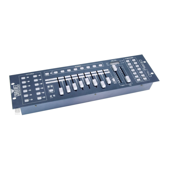
Obey™ 40 DMX Controller Ok on Dimmer Outdoor OK Sound Activated DMX512 Master/Slave 115V/230V Switch Replaceable Fuse User Serviceable Duty Cycle USER MANUAL Chauvet, 3000 N 29 Ct, Hollywood, FL 33020 U.S.A. (800) 762-1084 – (954) 929-1115 FAX (954) 929-5560 www.chauvetlighting.com... -
Page 2: Table Of Contents
ABLE OF ONTENTS BEFORE YOU BEGIN ............................ 3 ............................3 HAT IS INCLUDED ..........................3 NPACKING NSTRUCTIONS ........................... 3 AFETY NSTRUCTIONS INTRODUCTION ............................4 ..............................4 EATURES ) ........................5 RODUCT VERVIEW FRONT ) ........................ 6 RODUCT VERVIEW REAR PANEL ............................ -
Page 3: Before You Begin
There are no user serviceable parts inside the unit. Do not open the housing or attempt any repairs yourself. In the unlikely event your unit may require service, please contact CHAUVET at: 954-929-1115. Obey™ 40 User Manual Revised: 2008-06-13 15:54:24... -
Page 4: Introduction
NTRODUCTION The Obey™ 40 is a universal intelligent lighting controller. It allows the control of 12 fixtures composed of 16 channels each and up to 240 programmable scenes. Six chase banks can contain up to 240 steps composed of the saved scenes and in any order. Programs can be triggered by music, midi, automatically or manually. -
Page 5: Product Overview (Front)
This will adjust the hold time of a scene or a step within a chase Fade Time fader Also considered a cross-fade, sets the interval time between two scenes in a chase Strobe button Used for Chauvet strobes. Fog button Strobe button Reverse Channel LED... -
Page 6: Product Overview (Rear Panel)
DMX output connector DMX control signal DC Input jack Main power feed Strobe connector Chauvet Mono Strobe ¼” connector for built in strobe controller ON/OFF power switch Turns the controller on and off Fog connector Chauvet fog controller IEC connector Obey™... -
Page 7: Common Terms
Common Terms The following are common terms used in intelligent light programming. Blackout is a state where all lighting fixtures’ light output are set to 0 or off, usually on a temporary basis. DMX-512 is an industry standard digital communication protocol used in entertainment lighting equipment. -
Page 8: Operating Instructions
PERATING NSTRUCTIONS Setup S E T T IN G U P T H E SY S T EM Place the Obey™ 40 on a level surface. Note! The Obey™ 40 can also be rack mounted, occupying three rack spaces (3U). Plug the AC to DC power supply into the system back panel and into the mains outlet. -
Page 9: Physical Fader Assignment (Optional Setup)
PHYSIC AL FADER ASSIGNMENT (OPT IONAL SETUP) Use this feature to combine or unify fixture control attributes for different fixtures. For example; if you were controlling 4 moving mirrors and 4 moving yokes, the color, gobo and dimmer channels may not line up ideally on the physical faders. -
Page 10: Reverse Channel Output (Optional Setup)
R EVERSE CHANN EL OU TPUT (OPTIONAL SETU P) Notes Action You can permanently reverse the output of any given Press and hold PROGRAM & TAPSYNC channel on the controller. buttons together (2) times to access the channel assignment mode then select the FIXTURE button. -
Page 11: Programming
Programming A program (bank) is a sequence of different scenes (or steps) that will be called up one after another. In the Obey™ 40 30 programs can be created of 8 scenes in each. ENTER ING PROGRAM MOD E Press the PROGRAM button for 3 seconds until an LED dot next to the label PROG blinks. This indicates that the user is in programming mode. -
Page 12: Scene Copy
SCEN E COPY Notes Action Press the PROGRAM button for 3 seconds. Locate the scene in the program BANK. Use BANK UP/DOWN to navigate program banks. Select the SCENE in the program BANK to copy. Locate the destination scene in the program BANK. -
Page 13: Chase Programming
Chase Programming A chase is created by using previously created scenes. Scenes become steps in a chase and can be arranged in any order you choose. It is highly recommended that prior to programming chases for the first time; you delete all chases from memory. See “Delete All Chases” for instructions. CR EATE A CHA SE A Chase can contain 240 scenes as steps. -
Page 14: Adding A Step To A Chase
A D D ING A S T E P T O A C H A S E Notes Action Press and hold the PROGRAM button for 3 seconds to enter programming mode. Press the desired CHASE (1~6) button. Press the TAPSYNC/Display and the display will display the scene and bank number. -
Page 15: Delete All Chase Programs
D ELETE ALL CHA SE PROGRAMS CAUTION! This procedure will result in irrevocable loss of chase step memory. The individual scenes and program banks will be preserved. Notes Action Press and hold the BANK DOWN button and the AUTO DEL button while turning OFF the controller. -
Page 16: Playback (Chases)
Playback (Chases) MANUAL RUN CHA SES This function allows the user to manually step through each individual step in a chase. Notes Action Press and hold PROGRAM button for 3 seconds to enter programming mode. Start a chase by pressing any one of the CHASE buttons. -
Page 17: Midi Operation
Midi Operation The controller will only respond to MIDI commands on the MIDI channel when it is set to full stop. All MIDI control is performed using Note on commands. All other MIDI instructions are ignored. To stop a chase, send the blackout on note. Notes Action Press and hold the MIDI/ADD button until... -
Page 18: Appendix
XLR male to female connectors. The shield connection is pin 1, while pin 2 is Data Negative (S-) and pin 3 is Data positive (S+). CHAUVET carries 3-pin DMX compliant cables, DMX-10 (33’), DMX-4.5 (15’) and DMX-1.5 (5’) -
Page 19: Returns Procedure
Package must be clearly labeled with a Return Authorization Number (RA #). Products returned without an RA # will be refused. Call CHAUVET and request an RA # prior to shipping the fixture. Be prepared to provide the model number, serial number and a brief description of the cause for the return. -
Page 20: Dmx Dipswitch Quick Reference Chart
Appendix DMX Dipswitch Quick Reference Chart DMX Address Quick Reference Chart Dip Switch Position DMX DIP SWITCH 0=OFF 1=ON X=OFF or ON #1 #2 #3 #4 #5 32 64 33 65 34 66 35 67 36 68 100 37 69 101 38 70 102 39 71 103 40 72 104... -
Page 21: General Troubleshooting
Make sure connector is firmly connected to work device Stand alone mode All Chauvet lighting fixtures featuring stand- alone functions do not require additional settings, simply power the fixture and it will automatically enter into this mode Obey™ 40 User Manual... -
Page 22: Technical Specifications
Appendix Technical Specifications WEIGHT & DIMENSIONS Length......................... 20.25 in (514 mm) Width ..........................3.5 in (89 mm) Height ........................... 6.75 in (171 mm) Weight ..........................6 lbs (2.7 kg) POWER Operating Range ....................DC 9V-12V 500mA max Adapter ............................Provided THERMAL Maximum ambient temperature ..................