Table of Contents
Advertisement
Quick Links
Advertisement
Table of Contents
Troubleshooting

Related Manuals for Chauvet DMX-70


Summary of Contents for Chauvet DMX-70
-
Page 1: User Manual
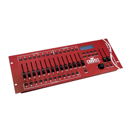
DMX-70 DMX Controller Ok on Dimmer Outdoor OK Sound Activated DMX512 Master/Slave 115V/230V Switch Replaceable Fuse User Serviceable Duty Cycle USER MANUAL Chauvet, 3000 N 29 Ct, Hollywood, FL 33020 U.S.A. (800) 762-1084 – (954) 929-1115 FAX (954) 929-5560 www.chauvetlighting.com... -
Page 2: Table Of Contents
ROGRAMMING Create a chase ..................................13 Copy Bank Into Chase ................................14 Adding a step to a chase................................ 14 Delete a scene/step in a Chase ............................. 14 Delete a Chase..................................15 Delete all Chase Programs ..............................15 )................................... 15 LAYBACK CENES Manual run scene................................... -
Page 3: Before You Begin
• This product is intended for indoor use only! • To prevent risk of fire or shock, do not expose fixture to rain or moisture. Make sure there are no flammable materials close to the unit while operating. • The unit must be installed in a location with adequate ventilation, at least 50cm from adjacent surfaces. -
Page 4: Introduction
The DMX-70 is a universal intelligent lighting controller. It allows the control of 12 fixtures composed of 32 channels each and up to 240 programmable scenes. Six chase banks can contain up to 240 steps composed of the saved scenes and in any order. Programs can be triggered by music, midi, automatically or manually. -
Page 5: Product Overview (Front)
Chase buttons Chase memory 1 ~ 6 Speed fader This will adjust the hold time of a scene or a step within a chase Fade Time fader Also considered a cross-fade, sets the fade time between two scenes in a chase Strobe button Used for CHAUVET strobes. -
Page 6: Product Overview (Rear Panel)
Product Overview (rear panel) Item Button or Fader Function MIDI input port For external triggering of banks, scenes, chases, and blackout using a MIDI device DMX polarity switch May be used to change signal polarity DMX output connector DMX control signal... -
Page 7: Common Terms
Common Terms The following are common terms used in intelligent light programming. Blackout is a state where all lighting fixtures’ light output are set to 0 or off, usually on a temporary basis. DMX-512 is an industry standard digital communication protocol used in entertainment lighting equipment. -
Page 8: Operating Instructions
Press and hold BANK UP and AUTO/DEL. Turn on power to the unit (while still holding BANK UP and AUTO/DEL). All LEDs will blink to indicate a successful reset. (Note: This process may take up to 15 seconds) FIXTUR E ADDR ESSING The DMX-70 is programmed to control 32 channels of DMX per fixture. -
Page 9: Physical Fader Assignment (Optional Setup)
F A D E R A S S I G N M E N T ” A N D “ R E V E R S E C H A N N E L O U T P U T ”... -
Page 10: Reverse Channel Output (Optional Setup)
(1) times to exit mode. F A D E T IM E A SS I G N ( O P T ION A L S E T U P ) You can choose whether the board’s fade time during scene execution is implemented broadly to all output channels or only to the Pan and Tilt movement channels. -
Page 11: Programming
Programming A program (bank) is a sequence of different scenes (or steps) that will be called up one after another. In the DMX-70 30 programs can be created of 8 scenes in each. ENTER ING PROGRAM MOD E Press the PROGRAM button for 3 seconds until “Program” is displayed. This indicates that the user is in programming mode. -
Page 12: Edit A Scene
D EL ETE SC EN E Notes Action The action of deleting a scene is actually a value reset Locate the scene in the program BANK. to 0 on all DMX channels available to the scene Use BANK UP/DOWN to navigate program memory. -
Page 13: Bank Copy
Bank. Chase Programming A chase is created by using previously created scenes. Scenes become steps in a chase and can be arranged in any order you choose. It is highly recommended that prior to programming chases for the first time;... -
Page 14: Copy Bank Into Chase
Press and hold the PROGRAM button for 3 seconds to exit programming mode. D EL E T E A S C EN E/S T E P I N A C H A S E Notes Action Remember that we use scene and steps Press and hold the PROGRAM button for 3 interchangeably. -
Page 15: Delete A Chase
CHASE button then release to delete the chase. All LED’s will blink 3 times. D ELETE ALL CHA SE PROGRAMS CAUTION! This procedure will result in irrevocable loss of chase step memory. The individual scenes and program banks will be preserved. Notes Action... -
Page 16: Running In Auto-Mode
You can change Banks while in operation by using the BANK UP/DOWN buttons. BLACKOUT The Blackout button brings all lighting output to 0 or off (also called the home position of the unit). Playback (Chases) MANUAL RUN CHA SES This function allows the user to manually step through each individual step in a chase. -
Page 17: Music Run Chases
Chases must already be programmed. Press either AUTO DEL or MUSIC BANK COPY buttons to select the trigger mode. The chases will run in the order they are pressed Press the CHASE button for each chase you wish to playback. -
Page 18: Midi Operation
Midi Operation The controller will only respond to MIDI commands on the MIDI channel when it is set to full stop. All MIDI control is performed using Note on commands. All other MIDI instructions are ignored. To stop a chase, send the blackout on note. -
Page 19: Appendix
DMX fixtures are designed to receive data through a serial Daisy Chain. A Daisy Chain connection is where the DATA OUT of one fixture connects to the DATA IN of the next fixture. The order in which the fixtures are connected is not important and has no effect on how a controller communicates to each fixture. -
Page 20: Returns Procedure
Package must be clearly labeled with a Return Authorization Number (RA #). Products returned without an RA # will be refused. Call CHAUVET and request an RA # prior to shipping the fixture. Be prepared to provide the model number, serial number and a brief description of the cause for the return. -
Page 21: Dmx Dipswitch Quick Reference Chart
Appendix DMX Dipswitch Quick Reference Chart DMX Address Quick Reference Chart Dip Switch Position DMX DIP SWITCH 0=OFF 1=ON X=OFF or ON #1 #2 #3 #4 #5 32 64 33 65 34 66 35 67 36 68 100 37 69 101... -
Page 22: General Troubleshooting
Some discharge lamps require a cooling off on after power period before the electronics in the fixture can failure kick start it again, wait 5 to 10 minutes before powering up Loss of signal Use only DMX cables Install terminator Note: Keep DMX cables separated from power cables or black lights. -
Page 23: Technical Specifications
Adapter ............................Provided THERMAL Maximum ambient temperature..................113° F (45°C) CONTROL & PROGRAMMING Data output ................... locking 3-pin XLR female socket Data pin configuration ................pin 1 shield, pin 2 (-), pin 3 (+) Protocols........................DMX-512 USITT ORDERING INFORMATION DMX-70 Controller........................DMX-70 DMX-70 User Manual...