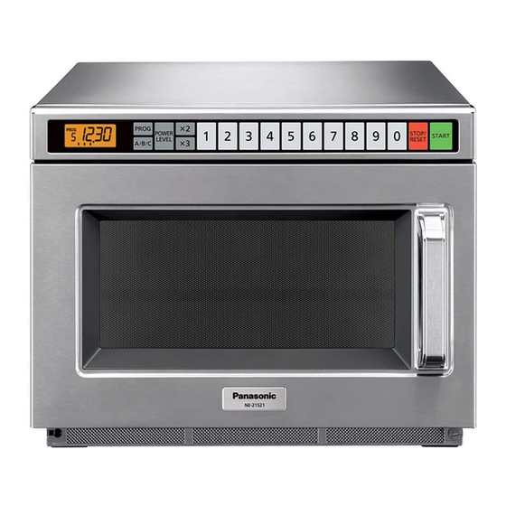
Panasonic NE-1257R Service Manual
Commercial microwave oven
Hide thumbs
Also See for NE-1257R:
- Operating instructions manual (32 pages) ,
- Technical bulletin (2 pages) ,
- Owner's manual (33 pages)
Table of Contents
Troubleshooting

Related Manuals for Panasonic NE-1257R


Summary of Contents for Panasonic NE-1257R
- Page 1 ORDER NO. MOD0009238C1 Commercial Microwave Oven NE-1257R/NE-1257CR NE-1757R/NE-1757CR NE-2157R/NE-2157CR NE-1258R © 2000 Matsushita Electric Industrial Co., Ltd. All rights reserved. Unauthorized copying distribution is a violation of law.
-
Page 2: Table Of Contents
NE-1257R/NE-1257CR / NE-1757R/NE-1757CR / NE-2157R/NE-2157CR / NE-1258R CONTENTS Page Page 1 OUTLINE DIAGRAM 7 SCHEMATIC DIAGRAM (NE-1757CR) 2 OPERATION PROCEDURE 8 SCHEMATIC DIAGRAM (NE-2157R) 3 WIRING REQUIREMENTS AND POWER SOURCE VOLTAGE 9 SCHEMATIC DIAGRAM (NE-2157CR) SELECTION 10 WIRING DIAGRAM (NE-1257R, NE-1258R) - Page 3 NE-1257R/NE-1257CR / NE-1757R/NE-1757CR / NE-2157R/NE-2157CR / NE-1258 14 WIRING DIAGRAM (NE-2157R) 24 PARTS LIST 15 WIRING DIAGRAM (NE-2157CR) 25 DOOR ASSEMBLY 16 DESCRIPTION OF OPERATING SEQUENCE 26 ESCUTCHEON BASE ASSEMBLY 17 CAUTIONS TO BE OBSERVED WHEN TROUBLESHOOTING 24 27 PACKING AND ACCESSORIES...
-
Page 4: Outline Diagram
NE-1257R/NE-1257CR / NE-1757R/NE-1757CR / NE-2157R/NE-2157CR / NE-1258R 1 OUTLINE DIAGRAM... -
Page 5: Operation Procedure
NE-1257R/NE-1257CR / NE-1757R/NE-1757CR / NE-2157R/NE-2157CR / NE-1258 2 OPERATION PROCEDURE... - Page 6 NE-1257R/NE-1257CR / NE-1757R/NE-1757CR / NE-2157R/NE-2157CR / NE-1258R...
- Page 7 NE-1257R/NE-1257CR / NE-1757R/NE-1757CR / NE-2157R/NE-2157CR / NE-1258...
- Page 8 NE-1257R/NE-1257CR / NE-1757R/NE-1757CR / NE-2157R/NE-2157CR / NE-1258R...
- Page 9 NE-1257R/NE-1257CR / NE-1757R/NE-1757CR / NE-2157R/NE-2157CR / NE-1258...
-
Page 10: Wiring Requirements And Power Source Voltage Selection
208 voltage will lower the power output of the oven, and store the black plug in the rectangular opening. resulting in slower heating of the food. Panasonic is NOT responsible for damage resulting from the use of the oven with other than specified voltage. -
Page 11: Schematic Diagram (Ne-1257R, Ne-1258R)
NE-1257R/NE-1257CR / NE-1757R/NE-1757CR / NE-2157R/NE-2157CR / NE-1258 4 SCHEMATIC DIAGRAM (NE-1257R, NE-1258R) -
Page 12: Schematic Diagram (Ne-1257Cr)
NE-1257R/NE-1257CR / NE-1757R/NE-1757CR / NE-2157R/NE-2157CR / NE-1258R 5 SCHEMATIC DIAGRAM (NE-1257CR) -
Page 13: Schematic Diagram (Ne-1757R)
NE-1257R/NE-1257CR / NE-1757R/NE-1757CR / NE-2157R/NE-2157CR / NE-1258 6 SCHEMATIC DIAGRAM (NE-1757R) -
Page 14: Schematic Diagram (Ne-1757Cr)
NE-1257R/NE-1257CR / NE-1757R/NE-1757CR / NE-2157R/NE-2157CR / NE-1258R 7 SCHEMATIC DIAGRAM (NE-1757CR) -
Page 15: Schematic Diagram (Ne-2157R)
NE-1257R/NE-1257CR / NE-1757R/NE-1757CR / NE-2157R/NE-2157CR / NE-1258 8 SCHEMATIC DIAGRAM (NE-2157R) -
Page 16: Schematic Diagram (Ne-2157Cr)
NE-1257R/NE-1257CR / NE-1757R/NE-1757CR / NE-2157R/NE-2157CR / NE-1258R 9 SCHEMATIC DIAGRAM (NE-2157CR) -
Page 17: Wiring Diagram (Ne-1257R, Ne-1258R)
NE-1257R/NE-1257CR / NE-1757R/NE-1757CR / NE-2157R/NE-2157CR / NE-1258 10 WIRING DIAGRAM (NE-1257R, NE-1258R) NOTE: When replacing, check the lead wire color as shown. -
Page 18: Wiring Diagram (Ne-1257Cr)
NE-1257R/NE-1257CR / NE-1757R/NE-1757CR / NE-2157R/NE-2157CR / NE-1258R 11 WIRING DIAGRAM (NE-1257CR) NOTE: When replacing, check the lead wire color as shown. -
Page 19: Wiring Diagram (Ne-1757R)
NE-1257R/NE-1257CR / NE-1757R/NE-1757CR / NE-2157R/NE-2157CR / NE-1258 12 WIRING DIAGRAM (NE-1757R) NOTE: When replacing, check the lead wire color as shown. -
Page 20: Wiring Diagram (Ne-1757Cr)
NE-1257R/NE-1257CR / NE-1757R/NE-1757CR / NE-2157R/NE-2157CR / NE-1258R 13 WIRING DIAGRAM (NE-1757CR) NOTE: When replacing, check the lead wire color as shown. -
Page 21: Wiring Diagram (Ne-2157R)
NE-1257R/NE-1257CR / NE-1757R/NE-1757CR / NE-2157R/NE-2157CR / NE-1258 14 WIRING DIAGRAM (NE-2157R) NOTE: When replacing, check the lead wire color as shown. -
Page 22: Wiring Diagram (Ne-2157Cr)
NE-1257R/NE-1257CR / NE-1757R/NE-1757CR / NE-2157R/NE-2157CR / NE-1258R 15 WIRING DIAGRAM (NE-2157CR) NOTE: When replacing, check the lead wire color as shown. -
Page 23: Description Of Operating Sequence
NE-1257R/NE-1257CR / NE-1757R/NE-1757CR / NE-2157R/NE-2157CR / NE-1258 16 DESCRIPTION OF OPERATING SEQUENCE Variable power cooking control in order to vary the output power of the microwave oven. One complete ON and OFF cycle of the power relay is 44 seconds. -
Page 24: Cautions To Be Observed When Troubleshooting
NE-1257R/NE-1257CR / NE-1757R/NE-1757CR / NE-2157R/NE-2157CR / NE-1258R 17 CAUTIONS TO BE OBSERVED WHEN TROUBLESHOOTING Unlike many other appliances, the microwave oven is high- voltage, high-current equipment. Though it is free from danger in ordinary use, extreme care should be taken during repair. -
Page 25: Confirm After Repair
NE-1257R/NE-1257CR / NE-1757R/NE-1757CR / NE-2157R/NE-2157CR / NE-1258 17.5. Confirm after repair 1. After repair or replacement of parts, make sure that the screws of the oven, etc. are neither loose nor missing. Microwave might leak if screws are not properly tightened. -
Page 26: Disassembly And Parts Replacement Procedure
NE-1257R/NE-1257CR / NE-1757R/NE-1757CR / NE-2157R/NE-2157CR / NE-1258R 18 DISASSEMBLY AND PARTS REPLACEMENT PROCEDURE 18.1. Replacement of magnetrons (Upper and Lower) Upper magnetron 1. Discharge electric charge remaining on the high voltage capacitors. 2. Remove the entire rear panel by removing screws as shown. -
Page 27: Circuit Board
NE-1257R/NE-1257CR / NE-1757R/NE-1757CR / NE-2157R/NE-2157CR / NE-1258 Removal of Positive Lock connector The positive lock connector is a specially designed loose free connector and you will find this connector in many lead wire connections. To remove this connector, pull the lead wire by pressing an extruded lever in the center of receptacle terminal as shown. - Page 28 NE-1257R/NE-1257CR / NE-1757R/NE-1757CR / NE-2157R/NE-2157CR / NE-1258R 18.4. Replacement of upper antenna 1. Remove ceiling plate by gently moving the left and right tabs inward while pulling the plate down and outward. 2. Using a small flat screwdriver or the like, remove two plastic clips located on the antenna ring.
- Page 29 NE-1257R/NE-1257CR / NE-1757R/NE-1757CR / NE-2157R/NE-2157CR / NE-1258 2. Remove 2 screws holding temp sensor and replace with new one. 3. Solder the lead wires securely to the sensor terminals. 18.7. Disassembly of door assembly 1. Remove each 2 bolts holding upper and lower hinges.
-
Page 30: Component Test Procedure
NE-1257R/NE-1257CR / NE-1757R/NE-1757CR / NE-2157R/NE-2157CR / NE-1258R 19 COMPONENT TEST PROCEDURE 19.1. High voltage transformer 1. Remove connections from the transformer terminals and check continuity. 2. Normal (cold) resistance readings should be as follows: Secondary winding Approx. 80 —120 Filament winding Approx. 0 Primary winding Approx. - Page 31 NE-1257R/NE-1257CR / NE-1757R/NE-1757CR / NE-2157R/NE-2157CR / NE-1258 one or both directions. 19.7. Temp sensor (Thermal protector) A temp sensor is mounted on exhaust guide. Its purpose is to automatically shut off the oven in case the cavity overheats for any reason.
-
Page 32: Measurements And Adjustments
NE-1257R/NE-1257CR / NE-1757R/NE-1757CR / NE-2157R/NE-2157CR / NE-1258R 20 MEASUREMENTS AND ADJUSTMENTS water using the thermometer and record the beaker's temperature (recorded as T1) 2. Place the beaker on the center of ceramic shelf. 3. Set the one to High power and heat it for exactly one minute. -
Page 33: Procedure For Measuring Microwave Energy Leakage
NE-1257R/NE-1257CR / NE-1757R/NE-1757CR / NE-2157R/NE-2157CR / NE-1258 21 PROCEDURE FOR MEASURING MICROWAVE ENERGY LEAKAGE periphery, the door viewing window, the exhaust opening and air inlet openings. 21.2. Record keeping and notification after measurement 1. After any adjustment or repair to a microwave oven, a leakage reading must be taken. - Page 34 NE-1257R/NE-1257CR / NE-1757R/NE-1757CR / NE-2157R/NE-2157CR / NE-1258R...
-
Page 35: Troubleshooting Guide
NE-1257R/NE-1257CR / NE-1757R/NE-1757CR / NE-2157R/NE-2157CR / NE-1258 22 TROUBLESHOOTING GUIDE... -
Page 36: Exploded View And Parts List
NE-1257R/NE-1257CR / NE-1757R/NE-1757CR / NE-2157R/NE-2157CR / NE-1258R 23 EXPLODED VIEW AND PARTS LIST... -
Page 37: Parts List
NE-1257R/NE-1257CR / NE-1757R/NE-1757CR / NE-2157R/NE-2157CR / NE-1258 24 PARTS LIST NOTE: When ordering replacement part(s), please use part number(s) shown in this parts list. Important safety notice: Components identified by mark have special characteristics important for safety. When replacing any of these components, use only manufacture's specified parts. - Page 38 NE-1257R/NE-1257CR / NE-1757R/NE-1757CR / NE-2157R/NE-2157CR / NE-1258R Ref. Part No. Part Name & Description Pcs/ Remarks A8251-3180 SPACER A3020-3850 DOOR HOOK A A3136-3470 HOOK SPACER A A3137-3850 HOOK SPACER B A3138-3470 HOOK SPACER C A31863960CP DOOR PANEL NE-1257CR A31863960AP DOOR PANEL...
- Page 39 NE-1257R/NE-1257CR / NE-1757R/NE-1757CR / NE-2157R/NE-2157CR / NE-1258 Ref. Part No. Part Name & Description Pcs/ Remarks A6408-3280 WASHER ANE65448U0AP SPACER A A6585-3280 P.C.B.HOLDER ANE66038U0AP OVEN LAMP BRACKET ANE66268U0AP THERMAL CUTOUT MOUNT NE-1257R NE-1258R NE-1757R A6688-3180 P.C.B.COVER A692M3650AP L.V.TRANSFORMER (U) NE-1257CR NE-1257R NE-1258R A692M3660AP L.V.TRANSFORMER (U)
-
Page 40: Door Assembly
NE-1257R/NE-1257CR / NE-1757R/NE-1757CR / NE-2157R/NE-2157CR / NE-1258R 25 DOOR ASSEMBLY Ref. Part No. Part Name & Description Pcs/ Remarks A3145-3500 DOOR SCREEN A ANE31468U0AP DOOR SCREEN B ANE30038U0AP DOOR FRAME(U) ANE301A8U0AP DOOR A A301H-3850 DOOR KEY LEVER B ANE301Q8U0AP DOOR E(U) -
Page 41: Escutcheon Base Assembly
NE-1257R/NE-1257CR / NE-1757R/NE-1757CR / NE-2157R/NE-2157CR / NE-1258 26 ESCUTCHEON BASE ASSEMBLY Ref. Part No. Part Name & Description Pcs/ Remarks A8337-3280 ESCUTCHEON SHEET A603M3310GP PC BOARD B (U) A64793310QP MEMBRANE SWITCH A6590-3280 FLAT CABLE ANE80018U0AP ESCUTCHEON A ANE80028U0AP ESCUTCHEON B... -
Page 42: Packing And Accessories
NE-1257R/NE-1257CR / NE-1757R/NE-1757CR / NE-2157R/NE-2157CR / NE-1258R 27 PACKING AND ACCESSORIES Ref. Part No. Part Name & Description Pcs/ Remarks A00033960CP INSTRUCTION BOOK NE-1257CR NE-1757CR NE-2157CR A00033960AP INSTRUCTION BOOK NE-1257R NE-1258R NE-1757R NE-2157R A04203960AP OPERATING GUIDE A01023960CP PACKING CASE PAPER... -
Page 43: Wiring Material
NE-1257R/NE-1257CR / NE-1757R/NE-1757CR / NE-2157R/NE-2157CR / NE-1258 28 WIRING MATERIAL Ref. Part No. Part Name & Description Pcs/ Remarks A030A3960CP LEAD WIRE HARNESS NE-1257CR A030A3960AP LEAD WIRE HARNESS NE-1257R NE-1258R A030A3970CP LEAD WIRE HARNESS NE-1757CR A030A3970AP LEAD WIRE HARNESS NE-1757R... -
Page 44: Ref. No. 89 L. V. Transformer (U)
NE-1257R/NE-1257CR / NE-1757R/NE-1757CR / NE-2157R/NE-2157CR / NE-1258R 29 REF. NO. 89 L. V. TRANSFORMER (U) Ref. Part No. Part Name & Description Pcs/ Remarks ANE61158U0AP POWER RELAYBRACKET ANE65448U0AP SPACER A ANE65458U0AP SPACER B A6338-3280 INSULATION SHEET B XYN3+F25S SCREW 3X25... - Page 45 NE-1257R/NE-1257CR / NE-1757R/NE-1757CR / NE-2157R/NE-2157CR / NE-1258 31 REF. NO. E2 P. C. BOARD (U) Ref. Part No. Part Name & Description Pcs/ Remarks CN250 AEEMHLIM21S CONNECTOR 21PIN DISP25 A64563080AP FLOURESCENT TUBE FV443 ANE82848U2AP SPACER...
-
Page 46: Digital Programmer Circuit
NE-1257R/NE-1257CR / NE-1757R/NE-1757CR / NE-2157R/NE-2157CR / NE-1258R 32 DIGITAL PROGRAMMER CIRCUIT SCHEMATIC DIAGRAM... - Page 47 NE-1257R/NE-1257CR / NE-1757R/NE-1757CR / NE-2157R/NE-2157CR / NE-1258...
-
Page 48: Digital Programmer Circuit
NE-1257R/NE-1257CR / NE-1757R/NE-1757CR / NE-2157R/NE-2157CR / NE-1258R 33 DIGITAL PROGRAMMER CIRCUIT PARTS LIST Ref. Part No. Part Name & Description Pcs/ Remarks EFBRL37C20 BUZZER 3.7KHZ C10 35 ECA1HM471B ELECTROLYTIC CAPACITOR AL 470MF/50V 36 37 ECA1HM221B ELECTROLYTIC CAPACITOR AL 220MF/50V C12 13...