Table of Contents
Advertisement
Advertisement
Table of Contents
Troubleshooting

Related Manuals for Hitachi L2002


Summary of Contents for Hitachi L2002
- Page 1 Series Inverter Instruction Manual • Single-phase Input 200V Class • Three-phase Input • Three-phase Input Manual Number: NB675X Sept. 2006 Hitachi Industrial Equipment Systems Co., Ltd. 200V Class 400V Class After reading this manual, keep it handy for future reference.
-
Page 3: Hazardous High Voltage
Safety Messages For the best results with the L200 the warning labels attached to the inverter before installing and operating it, and follow the instructions exactly. Keep this manual handy for quick reference. Definitions and Symbols A safety instruction (message) includes a “Safety Alert Symbol” and a signal word or phrase such as WARNING or CAUTION. -
Page 4: General Precautions - Read These First
CAUTION: Proper grounds, disconnecting devices and other safety devices and their location are the responsibility of the user and are not provided by Hitachi Industrial Equipment Systems Co., Ltd. CAUTION: Be sure to connect a motor thermal disconnect switch or overload device to... - Page 5 Cable support Cable CAUTION: A double-pole disconnection device must be fitted to the incoming main power supply close to the inverter. Additionally, a protection device meeting IEC947-1/ IEC947-3 must be fitted at this point (protection device data shown in “Determining Wire and Fuse Sizes”...
-
Page 6: Index To Warnings And Cautions In This Manual
Index to Warnings and Cautions in This Manual Cautions and Warnings for Orientation and Mounting Procedures CAUTION: Hazard of electrical shock. Disconnect incoming power before working on this control. Wait five (5) minutes before removing the front cover. CAUTION: Be sure to install the unit on flame-resistant material such as a steel plate. - Page 7 LFU models • Three phase 380 to 480 V 50/60Hz for HFEF models CAUTION: If you power a 3-phase-only inverter with single phase power, you must derate the output current. Be sure to call your Hitachi distributor for assistence. Otherwise, there is the possibility of damage to the inverter and the danger of fire.
- Page 8 CAUTION: Be sure not to connect an AC power supply to the output terminals. Otherwise, there is the possibility of damage to the inverter and the danger of injury and/or fire. CAUTION: Remarks for using ground fault interrupter breakers in the...
- Page 9 (be sure to design the machine so that safety for personnel is secure even if it restarts.) Otherwise, it may cause injury to personnel. WARNING: If the power supply is cut OFF for a short period of time, the inverter may restart operation after the power supply recovers if the Run command is active.
- Page 10 viii WARNING: Be sure not to touch the inside of the energized inverter or to put any conductive object into it. Otherwise, there is a danger of electric shock and/or fire. WARNING: If power is turned ON when the Run command is already active, the motor will automatically start and injury may result.
-
Page 11: General Warnings And Cautions
Warnings and Cautions for Troubleshooting and Maintenance WARNING: Wait at least five (5) minutes after turning OFF the input power supply before performing maintenance or an inspection. Other- wise, there is the danger of electric shock. WARNING: Make sure that only qualified personnel will perform maintenance, inspection, and part replacement. - Page 12 (Mgo) on the power supply side, so that the circuit does not allow automatic restarting after the power supply recovers. If the optional remote operator is used and the retry function has been selected, this will also cause automatic restarting when a Run command is active.
- Page 13 MUST install an input-side AC reactor of 3% (at a voltage drop at rated current) with respect to the supply voltage on the power supply side. Also, where the effects of an indirect lightning strike are possible, install a lightning conductor.
-
Page 14: Ul® Cautions, Warnings, And Instructions
CAUTION: When the EEPROM error E08 occurs, be sure to confirm the setting values again. CAUTION: When using normally closed active state settings (C011 to C015) for exter- nally commanded Forward or Reverse terminals [FW] or [RV], the inverter may start automatically when the external system is powered OFF or disconnected from the inverter! So, do not use normally closed active state settings for Forward or Reverse terminals [FW] or [RV] unless your system design protects against unintended motor... - Page 15 Terminal Tightening Torque and Wire Size The wire size range and tightening torque for field wiring terminals are presented in the tables below. Motor Output Input Voltage L200-002NFE(F)2/NFU2 L200-004NFE(F)2/NFU2 0.55 L200-005NFE(F)2 0.75 L200-007NFE(F)2/NFU2 1 1/2 L200-011NFE(F)2 200V L200-015NFE(F)2/NFU2 L200-022NFE(F)2/NFU2 L200-037LFU2 7 1/2 L200-055LFU2 L200-075LFU2...
-
Page 16: Motor Overload Protection
0.75 200V 0.75 400V Motor Overload Protection Hitachi L200 inverters provide solid state motor overload protection, which depends on the proper setting of the following parameters: • B012 “electronic overload protection” • B212 “electronic overload protection, 2nd motor” Set the rated current [Amperes] of the motor(s) with the above parameters. The setting range is 0.2 * rated current to 1.2 * rated current. -
Page 17: Table Of Contents
Table of Contents Safety Messages Hazardous High Voltage General Precautions - Read These First! Index to Warnings and Cautions in This Manual General Warnings and Cautions UL® Cautions, Warnings, and Instructions Table of Contents Revisions Contact Information Chapter 1: Getting Started Introduction Inverter Specifications Introduction to Variable-Frequency Drives... - Page 18 Connecting the Inverter to ModBus Network Protocol Reference ModBus Data Listing Appendix C: Drive Parameter Settings Tables Introduction Parameter Settings for Keypad Entry Appendix D: CE–EMC Installation Guidelines CE–EMC Installation Guidelines Hitachi EMC Recommendations Index 4–2 4–4 4–6 4–7 4–9 4–35 4–53...
-
Page 19: Revisions
xvii L200 Inverter Revisions Revision History Table Operation Revision Comments Date of Issue Manual No. Initial release of manual NB675X Sept. 2006 NB675X... -
Page 20: Contact Information
NOTE: To receive technical support for the Hitachi inverter you purchased, contact the Hitachi inverter dealer from whom you purchased the unit, or the sales office or factory contact listed above. Please be prepared to provide the following inverter nameplate information: 1. - Page 21 Getting Started In This Chapter... — Introduction — Inverter Specifications — Introduction to Variable-Frequency Drives — Frequently Asked Questions page...
-
Page 22: Introduction
• Continuous operation at 100% torque within a 1:10 speed range (6/60 Hz / 5/50 Hz) without motor derating A full line of accessories from Hitachi is available to complete your motor application: • Digital remote operator keypad • Panel-mount keypad bezel kit and DIN rail mounting adapter (35mm rail size) •... - Page 23 (below left). A cable (part no. ICS–1 or ICS–3, 1m or 3m) connects the modular connectors of the keypad and inverter. Hitachi provides a panel mount keypad kit OPE–SRmini (below, right). It includes the mounting flange, gasket, keypad, and other hardware. You can mount the keypad with the potentiometer for a NEMA1 rated installation.
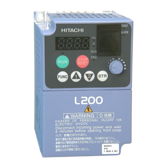
- Page 24 1–4 Introduction Inverter Specifications Label The Hitachi L200 as pictured below. Be sure to verify that the specifications on the labels match your power source, motor, and application safety requirements. Specifications label Regulatory agency approval labels (opposite side) Inverter model number...
-
Page 25: Inverter Specifications
Inverter Specifications Model-specific tables for 200V and 400V class inverters The following tables are specific to L200 groups. Note that “General Specifications” on page 1–10 groups. Footnotes for all specifications tables follow the table below. Item L200 inverters, EU types 200V models USA type Applicable motor size *2... - Page 26 (for Low Voltage Directive). Note 7: At the rated voltage when using a Hitachi standard 3-phase, 4-pole motor. Note 8: The braking torque via capacitive feedback is the average deceleration torque at the shortest deceleration (stopping from 50/60 Hz as indicated).
- Page 27 L200 Inverter Specifications, continued... Item L200 inverters, EU types 200V models USA type Applicable motor size *2 Rated capacity 230V (kVA) 240V Rated input voltage Integrated EMC NFEF type filter NFE, NFU types Rated input 1-phase current (A) 3-phase Rated output voltage *3 Rated output current (A) Efficiency at 100% rated output (%) Watt loss,...
- Page 28 1–8 Inverter Specifications Item L200 inverters, EU types 400V models USA type Applicable motor size *2 Rated capacity (460V) kVA Rated input voltage *6 Integrated EMC HFEF type filter HFE, HFU types Rated input current (A) Rated output voltage *3 Rated output current (A) Efficiency at 100% rated output (%) Watt loss,...
- Page 29 Item L200 inverters, EU types 400V models USA type Applicable motor size *2 Rated capacity (460V) kVA Rated input voltage *6 Integrated EMC HFEF type filter HFE, HFU types Rated input current (A) Rated output voltage *3 Rated output current (A) Efficiency at 100% rated output (%) Watt loss, at 70% output...
-
Page 30: General Specifications
1–10 Inverter Specifications General Specifications The following table applies to all L200 Item Protective housing *1 Control method Carrier frequency Output frequency range *4 Frequency accuracy Frequency setting resolution Volt./Freq. characteristic Overload capacity Acceleration/deceleration time Input Freq. Operator panel Up and Down keys / Value settings signal setting Potentiometer... - Page 31 Item Other functions Protective function Operat- Temperature Humidity Environ ment Vibration *12 Location Coating color Options Signal Ratings Detailed ratings are in “Control Logic Signal Specifications” on page Signal / Contact Built-in power for inputs 24VDC, 30 mA maximum Discrete logic inputs 27VDC maximum Discrete logic outputs 50mA maximum ON state current, 27 VDC maximum OFF state voltage...
-
Page 32: Derating Curves
Use the following derating curves to help determine the optimal carrier frequency setting for your inverter and find the output current derating. Be sure to use the proper curve for your particular L200 Legend for Graphs: Enclosure POWER HITACHI ALARM 5 0.0 STOP RESET FUNC. - Page 33 Derating curves: L200–002NFE(F)2/NFU2 100% % of rated output current L200–004NFE(F)2/ 100% NFU2, –005NFE(F)2 % of rated output current L200–007NFE(F)2/ NFU2, –011NFE(F)2 100% % of rated output current L200 Inverter Carrier frequency Carrier frequency Carrier frequency 1–13...
- Page 34 1–14 Inverter Specifications Derating curves, continued... L200–015NFE(F)2/NFU2 % of rated output current L200–022NFE(F)2/NFU2 % of rated output current L200–037LFU2 % of rated output current 100% Carrier frequency 100% Carrier frequency 100% Carrier frequency...
- Page 35 Derating curves, continued... L200–055LFU2 100% % of rated output current L200–075LFU2 100% % of rated output current L200–004HFE(F)2/HFU2 100% % of rated output current L200 Inverter Carrier frequency Carrier frequency Carrier frequency 1–15...
- Page 36 1–16 Inverter Specifications Derating curves, continued... L200–007HFE(F)2/HFU2 % of rated output current L200–015HFE(F)2/HFU2 % of rated output current L200–022HFE(F)2/HFU2 % of rated output current 100% Carrier frequency 100% Carrier frequency 100% Carrier frequency...
- Page 37 Derating curves, continued... L200–030HFE(F)2, -040HFE(F)/HFU2 100% % of rated output current L200–055HFE(F)2/HFU2 100% % of rated output current L200–075HFE(F)2/HFU2 100% % of rated output current L200 Inverter Carrier frequency Carrier frequency Carrier frequency 1–17...
-
Page 38: Introduction To Variable-Frequency Drives
Introduction to Variable-Frequency Drives The Purpose of Motor Speed Control for Industry Hitachi inverters provide speed control for 3-phase AC induction motors. You connect AC power to the inverter, and connect the inverter to the motor. Many applications benefit from a motor with variable speed, in several ways: •... - Page 39 Inverter Input and Three-Phase Power The Hitachi L200 Series of inverters includes two sub-groups: the 200V class and the 400V class inverters. The drives described in this manual may be used in either the United States or Europe, although the exact voltage level for commercial power may be slightly different from country to country.
- Page 40 The Hitachi inverter is a rugged and reliable device. The intention is for the inverter to assume the role of controlling power to the motor during all normal operations. There- fore, this manual instructs you not to switch off power to the inverter while the motor is running (unless it is an emergency stop).
- Page 41 For loads that continuously overhaul the motor for extended periods of time, the L200 Hitachi distributor). For loads that continuously overhaul the motor for extended periods of time, the L200 may not be suitable (contact your Hitachi distributor).
- Page 42 1–22 Introduction to Variable-Frequency Drives Velocity Profiles The L200 inverter is capable of sophisticated speed control. A graphical representation of that capability will help you understand and configure the associated parameters. This manual makes use of the velocity profile graph used in industry (shown at right). In the example, acceleration is a ramp to a set speed, and deceleration is a decline to a stop.
-
Page 43: Frequently Asked Questions
Frequently Asked Questions What is the main advantage in using an inverter to drive a motor, compared to alternative solutions? An inverter can vary the motor speed with very little loss of efficiency, unlike mechanical or hydraulic speed control solutions. The resulting energy savings usually pays for the inverter in a relatively short time. - Page 44 How many poles should the motor have? Hitachi inverters can be configured to operate motors with 2, 4, 6, or 8 poles. The greater the number of poles, the slower the top motor speed will be, but it will have higher torque at the base speed.
- Page 45 Several options related to electrical noise suppression are available for the Hitachi inverters. How can I know if my application will require any of these options? The purpose of these noise filters is to reduce the inverter electrical noise so the operation of nearby electrical devices is not affected.
- Page 47 Inverter Mounting and Installation In This Chapter... — Orientation to Inverter Features — Basic System Description — Step-by-Step Basic — Powerup Test — Using the Front Panel Keypad Installation... page...
-
Page 48: Orientation To Inverter Features
The Store key is used when changing a setting. inverter Quick Reference Guide , and inverter and perform these steps: POWER HITACHI ALARM 5 0.0 STOP RESET FUNC. - Page 49 Front Housing Cover HIGH VOLTAGE: Hazard of electrical shock. Disconnect incoming power before working on this control. Wait five (5) minutes before removing the front cover. To remove the cover, follow the steps below (applies to all inverter models): 1. Press downward on the cover at the two areas indicated to release the retaining tabs. 2.
- Page 50 2–4 Orientation to Inverter Features Logic Connector Introduction After removing the front housing cover, take a moment to become familiar with the connectors, as shown below. Relay output Logic and analog contacts signal connections...
-
Page 51: Connecting The Inverter To Modbus
NOTE: L200 inverters have built-in ModBus RTU RS-485 communications. Connect- ing to other networks such as DeviceNet, Ethernet, CANopen, and ProfiBus is possible by adding optional, external interface devices. Contact your Hitachi distributor for more information. 4–9. “Connecting the Inverter to ModBus” on page B–3 3–10. - Page 52 2–6 Orientation to Inverter Features Power Wiring Access - First, ensure no power source of any kind is connected to the inverter. If power has been connected, wait five minutes after powerdown and verify the Power LED is OFF to proceed. After removing the front housing cover, the housing partition that covers the power wiring exit will be able to slide upward as shown to the right.
-
Page 53: Basic System Description
Input-side This is useful in suppressing harmonics induced on the AC Reactor power supply lines and for improving the power factor. WARNING: Some applications must use an input- side AC reactor to prevent inverter damage. See Warning on next page. -
Page 54: Step-By-Step Basic Installation
MUST install an input-side AC reactor of 3% (at a voltage drop at rated current) with respect to the supply voltage on the power supply side. Also, where the effects of an indirect lightning strike are possible, install a lightning conductor. - Page 55 2–9 L200 Inverter Choosing a Mounting Location Step 1: Study the following caution messages associated with mounting the inverter. This is the time when mistakes are most likely to occur that will result in expensive rework, equipment damage, or personal injury. CAUTION: Be sure to install the unit on flame-resistant material such as a steel plate.
- Page 56 In order to ensure enough room for air circulation around the inverter to aid in cooling, maintain the speci- fied clearance around the inverter specified in the diagram. Clear area HITACHI 5 0.0 STOP RESET FUNC.
- Page 57 Check Inverter Dimensions Step 4: Locate the applicable drawing on the following pages for your inverter. Dimensions are given in millimeters (inches) format. L200–002NFU2, -002NFEF2, –004NFU2, -004NFEF2, –005NFEF2 5(0.20) 5(0.20) 67(2.64) 80(3.15) NOTE: Some inverter housings require two mounting screws, while others require four. Be sure to use lock washers or other means to ensure screws do not loosen due to vibration.
- Page 58 2–12 Step-by-Step Basic Installation Dimensional drawings, continued... L200–004HFU2, –004HFEF2, –007NFEF2 98(3.86) 110(4.33) 2-φ5(0.20) 5(0.20) Model -004HFU2 -004HFEF2 -007NFEF2 130(5.130) 155(6.10) 155(6.10)
- Page 59 Dimensional drawings, continued... L200–007HFU2, –007HFEF2 98(3.86) 110(4.33) 2-φ5(0.20) 4(0.16) 5(0.20) Model -007HFU2 -007HFEF2 2–13 L200 Inverter 130(5.130) 155(6.10)
- Page 60 2–14 Step-by-Step Basic Installation Dimensional drawings, continued... L200–007NU2, -015NFU2, 015HFU2,-022NFU2, -022HFU2, -037LFU2, -040HFU2, - 011NFEF2, -015NFEF2, -015HFEF2, -022NFEF2, -022HFEF2, -030HFEF2, -040HFEF2 98(3.86) 110(4.33) 2-φ5(0.20) 5(0.20) Model -007NFU2 -015NFU2 -015HFU2 -022NFU2 -022HFU2 -037LFU2 -040HFU2 -011NFEF2 -015NFEF2 -015HFEF2 -022NFEF2 -022HFEF2 -030HFEF2 -040HFEF2 130(5.12) 129(5.08) 130(5.12)
- Page 61 Dimensional drawings, continued... L200–055LFU2, –055HFU2, –075LFU2, -075HFU2, –055HFEF2, -075HFEF2 6(0.24) 164(6.46) 180(7.09) L200 2-φ5(0.20) 6.5(0.25) Model -055LFU2 -055HFU2 -075LFU2 -075HFU2 -055HFEF2 -075HFEF2 2–15 Inverter 205(8.07) 205(8.07) 205(8.07) 205(8.07) 250(9.84) 250(9.84)
- Page 62 HIGH VOLTAGE: Wiring work shall be carried out only by qualified personnel. Other- wise, there is a danger of electric shock and/or fire. HIGH VOLTAGE: Implement wiring after checking that the power supply is OFF. Oth- erwise, you may incur electric shock and/or fire.
- Page 63 Determining Wire and Fuse Sizes The maximum motor currents in your application determines the recommended wire size. The following table gives the wire size in AWG. The “Power Lines” column applies to the inverter input power, output wires to the motor, the earth ground connection, and any other component shown in the “Signal Lines”...
- Page 64 2–18 Step-by-Step Basic Installation Terminal Dimensions and Torque Specs The terminal screw dimensions for all L200 information is useful in sizing spade lug or ring lug connectors for wire terminations. CAUTION: Fasten the screws with the specified fastening torque in the table below. Check for any loosening of screws.
- Page 65 Please use the terminal arrangement below corresponding to your inverter model. Inverter models L200–002NFEF2/NFU2, –004NFEF2/NFU2, –005NFEF2 Jumper Inverter models L200–007NFEF2 to –022NFEF2, –037LFU2, –004HFEF2/HFU2 to –040HFEF2/HFU2 NFEF, NFU R/L1 S/L2 T/L3 LFU, HFEF, HFU Inverter models L200–055LFU2, –055HFE2/HFU2, –075LFU2, –075HFE2/HFU2 R/L1 S/L2 T/L3 PD/+1 Inverter models L200–055HFEF2, –075HFEF2...
- Page 66 CAUTION: If you power a 3-phase-only inverter with single phase power, you must derate the output current. Be sure to call your Hitachi distributor for assistence. Other- wise, there is the possibility of damage to the inverter and the danger of fire.
- Page 67 Wire the Inverter Output to Motor Step 7: The process of motor selection is beyond the scope of this manual. However, it must be an AC induction motor with three phases. It should also come with a chassis ground lug. If the motor does not have three power input leads, stop the installation and verify the motor type.
-
Page 68: Powerup Test
• The inverter is connected to a power source and motor. • No additional wiring of inverter connectors or terminals has been done. • The power supply is reliable, and the motor is a known working unit, and the motor nameplate ratings match the inverter ratings. - Page 69 Please study the following instructions and messages before proceeding with the powerup test. 1. The power supply must have fusing suitable for the load. Check the fuse size chart presented in Step 5, if necessary. 2. Be sure you have access to a disconnect switch for the drive input power if necessary.
-
Page 70: Using The Front Panel Keypad
• Store ( ) Key - When the unit is in Program Mode and you have edited a parameter value, press the Store key to write the new value to the EEPROM. Serial port POWER HITACHI ALARM 5 0.0 STOP RESET FUNC. - Page 71 50 Hz or 60 Hz. To edit the parameter, the inverter must be in Program Mode (PRG LED will be ON). You use the front panel keys to first select the function code “A004.” After displaying the value for “A004,” use the Up/Down ( POWER HITACHI ALARM A - - - STOP RESET FUNC.
- Page 72 2–26 Using the Front Panel Keypad Keypad Navigational Map The L200 Series inverter drives have many programmable functions and parameters. Chapter 3 will cover these in detail, but you need to access just a few items to perform the powerup test. The menu structure makes use of function codes and parameter codes to allow programming and monitoring with only a 4-digit display and a few keys and LEDs.
- Page 73 “Restoring Factory Default Settings” 2–5. for orientation through- Display Func./Parameter Inverter output frequency displayed (0Hz in Stop Mode). “D” Group selected 0 0 1 “A” Group selected A – – – Potentiometer Enable LED HITACHI 5 0.0 STOP RESET FUNC. 2–27 POWER ALARM...
- Page 74 03 = ModBus network 10 = Calculate function output 00 = potentiometer (selected) Stores parameter, returns to “A” A 0 0 1 Group list Run Key Enable LED HITACHI 5 0.0 STOP RESET FUNC. Display Func./Parameter Speed command source setting...
- Page 75 Set the Motor Base Frequency - The motor is designed to operate at a specific AC frequency. Most commercial motors are designed for 50/60 Hz operation. First, check the motor specifications. Then follow the steps below to verify the setting or correct it for your motor.
- Page 76 2–30 Using the Front Panel Keypad Action (Starting point) key and hold until--> Press the key. Press the FUNC. Press the key. Press the Set the Motor Current - The inverter has thermal overload protection that is designed to protect the inverter and motor from overheating due to an excessive load. The inverter’s uses the motor’s current rating to calculate the time-based heating effect.
- Page 77 Set the Number of Motor Poles - The motor’s internal winding arrangement deter- mines its number of magnetic poles. The specifications label on the motor usually indicates the number of poles. For proper operation, verify the parameter setting matches the motor poles. Many industrial motors have four poles, corresponding to the default setting in the inverter (H004).
-
Page 78: Running The Motor
7. Now, press the RUN key on the keypad. The RUN LED will turn ON. 8. Slowly increase the potentiometer setting in clockwise fashion. The motor should start turning. 9. Press the STOP key to stop the motor rotation. HITACHI 5 0.0 STOP RESET FUNC. - Page 79 NOTE: Some factory automation devices such as PLCs have alternate Run/Program modes; the device is in either one mode or the other. In the Hitachi inverter, however, Run Mode alternates with Stop Mode, and Program Mode alternates with Monitor Mode.
-
Page 81: Configuring Drive Parameters
Configuring Drive Parameters In This Chapter... — Choosing a Programming Device — Using Keypad Devices — “D” Group: Monitoring — “F” Group: Main Profile Parameters — “A” Group: Standard Functions — “B” Group: Fine Tuning Functions — “C” Group: Intelligent Terminal —... -
Page 82: Choosing A Programming Device
Choosing a Programming Device Introduction Hitachi variable frequency drives (inverters) use the latest electronics technology for getting the right AC waveform to the motor at the right time. The benefits are many, including energy savings and higher machine output or productivity. The flexibility required to handle a broad range of applications has required ever more configurable options and parameters—inverters are now a complex industrial automation component. -
Page 83: Using Keypad Devices
) Key - When the unit is in Program Mode and you have edited a parameter value, press the Store key to write the new value to the EEPROM. L200 Power LED Serial port Alarm LED POWER HITACHI ALARM Run/Stop LED 5 0.0 Program/Monitor LED STOP RESET Potentiometer Enable LED FUNC. - Page 84 3–4 Using Keypad Devices Keypad Navigational Map You can use the inverter’s front panel keypad to navigate to any parameter or function. The diagram below shows the basic navigational map to access these items. Monitor Mode PRG LED=OFF Display Data 0 0 0.0 FUNC.
-
Page 85: Operational Modes
Operational Modes The RUN and PRG LEDs tell just part of the story; Run Mode and Program Modes are independent modes, not opposite modes. In the state diagram to the right, Run alternates with Stop, and Program Mode alternates with Monitor Mode. This is a very important ability, for it shows that a technician can approach a running machine and change some parameters without shutting down the machine. -
Page 86: D" Group: Monitoring Functions
3–6 “D” Group: Monitoring Functions “D” Group: Monitoring Functions You can access important system parameter values with the “D” Group monitoring functions, whether the inverter is in Run Mode or Stop Mode. After selecting the function code number for the parameter you want to monitor, press the Function key once to show the value on the display. - Page 87 Func. Name / Code SRW Display D007 Scaled output frequency monitor F-Cnv 00000.00 D013 Output voltage monitor Vout 00000V D016 Cumulative operation RUN time monitor 0000000hr D017 Cumulative power-on time monitor 0000000hr Trip Event and History Monitoring The trip event and history monitoring feature lets you cycle through related information using the keypad.
- Page 88 3–8 “D” Group: Monitoring Functions Local Monitoring During Network Operation The L200 inverter’s serial port may be connected to a network or to an external digital operator. During those times, the inverter keypad keys will not function (except for the Stop key).
-
Page 89: F" Group: Main Profile Parameters
“F” Group: Main Profile Parameters The basic frequency (speed) profile is defined by parameters contained in the “F” Group as shown to the right. The set running frequency is in Hz, but accelera- tion and deceleration are specified in the time duration of the ramp (from zero to maximum frequency, or from maximum frequency to zero). -
Page 90: A" Group: Standard Functions
3–10 “A” Group: Standard Functions “A” Group: Standard Functions Control Source Settings The inverter provides flexibility in how you control Run/Stop operation and set the output frequency (motor speed). It has other control sources that can override the A001/ A002 settings. Parameter A001 sets the source selection for the inverter’s output frequency. - Page 91 Run Command Source Setting - For parameter A002, the following table provides a further description of each option, and a reference to other page(s) for more information Code Run Command Source Control terminal - The [FW] or [RV] input terminals control Run/Stop operation Keypad Run key - The Run and Stop keys provide control ModBus network input - The network has a dedicated coil...
- Page 92 3–12 “A” Group: Standard Functions The inverter has other control sources that can temporarily override the parameter A001 setting, forcing a different output frequency source. The following table lists all frequency source setting methods and their relative priority (“1” is the highest priority). Priority [CF1] to [CF4] Multi-speed terminals [OPE] Operator Control intelligent input...
- Page 93 Basic Parameter Settings These settings affect the most fundamental behavior of the inverter—the outputs to the motor. The frequency of the inverter’s AC output determines the motor speed. You may select from three different sources for the reference speed. During application develop- ment you may prefer using the potentiometer, but you may switch to an external source (control terminal setting) in the finished application, for example.
- Page 94 3–14 “A” Group: Standard Functions Analog Input Settings The inverter has the capability to accept an external analog input that can command the output frequency to the motor. Voltage input (0 –10V) and current input (4–20mA) are available on separate terminals ([O] and [OI], respectively). Terminal [L] serves as signal ground for the two analog inputs.
- Page 95 “A” Function Func. Name / Code SRW Display A005 [AT] selection Four options, select codes: 00 .. Select between [O] and AT-Slct O/OI [OI] at [AT] 01 .. [O] + [OI] ([AT] input is ignored) 02 .. Select between [O] and keypad potentiometer 03 ..
- Page 96 3–16 “A” Group: Standard Functions The example graph below shows a typical analog input waveform. The filter removes the noise spikes. When a speed change (such as level increase) occurs, the filter naturally has a delayed response. Due to the deadband feature (A016=17), the final output changes only when the 16-sample average moves past the deadband threshold.
- Page 97 “A” Function Func. Name / Code SRW Display A020 Multi-speed frequency Defines the first speed of a setting multi-speed profile, range is 0.0 / start frequency to 400 Hz SPD 00s 0000.0Hz A020 = Speed 0 (1st motor) A220 Multi-speed frequency Defines the first speed of a setting, 2nd motor multi-speed profile for 2nd...
- Page 98 3–18 “A” Group: Standard Functions Torque Control Algorithms The inverter generates the motor output according to the V/f algorithm selected. Parameter A044 selects the inverter algorithm for generating the frequency output, as shown in the diagram to the right (A244 for 2nd motor).
- Page 99 Be aware that running the motor at a low speed for a long time can cause motor overheating. This is particularly true when manual torque boost is ON, or if the motor relies on a built-in fan for cooling. NOTE: Manual torque boost applies only to constant torque (A044=00) and variable torque (A044=01) V/f control.
- Page 100 3–20 “A” Group: Standard Functions “A” Function Func. Name / Code SRW Display A244 V/f characteristic curve selection, 2nd motor 2CTRL C-TRQ A045 V/f gain setting V-Gain 00100% A245 V/f gain setting, 2nd motor 2V-Gain 00100% Mode Edit Description Lo Hi ✘...
- Page 101 DC Braking Settings The DC braking feature can provide additional stopping torque when compared to a normal deceleration to a stop. DC braking is particularly useful at low speeds when normal decelera- tion torque is minimal. When you enable DC braking, the inverter injects a DC voltage into the motor windings during deceleration below a frequency you can specify (A052).
- Page 102 3–22 “A” Group: Standard Functions Frequency-related Functions Frequency Limits – Upper and lower limits can be imposed on the inverter output frequency. These limits will apply regardless of the source of the speed refer- ence. You can configure the lower frequency limit to be greater than zero as shown in the graph.
- Page 103 Jump Frequencies – Some motors or machines exhibit resonances at particular speed(s), which can be destructive for prolonged running at those speeds. The inverter has up to three jump frequencies as shown in the graph. The hysteresis around the jump frequencies causes the inverter output to skip around the sensitive frequency values.
-
Page 104: Pid Control
3–24 “A” Group: Standard Functions PID Control When enabled, the built-in PID loop calculates an ideal inverter output value to cause a loop feedback process variable (PV) to move closer in value to the setpoint (SP). The frequency command serves as the SP. The PID loop algorithm will read the analog input for the process variable (you specify the current or voltage input) and calculate the output. - Page 105 Automatic Voltage Regulation (AVR) Function The automatic voltage regulation (AVR) feature keeps the inverter output waveform at a relatively constant amplitude during power input fluctuations. This can be useful if the installation is subject to input voltage fluctuations. However, the inverter cannot boost its motor output to a voltage higher than the power input voltage.
- Page 106 3–26 “A” Group: Standard Functions Second Acceleration and Deceleration Functions The L200 inverter features two-stage acceleration and deceleration ramps. This gives flexibility in the profile shape. You can specify the frequency transition point, the point at which the standard acceleration (F002) or deceleration (F003) changes to the second acceleration (A092) or deceleration (A093).
- Page 107 “A” Function Func. Name / Code SRW Display A095 Acc1 to Acc2 frequency Output frequency at which transition point Accel1 switches to Accel2, range is 0.0 to 400.0 Hz ACC CHfr0000.0Hz A295 Acc1 to Acc2 frequency Output frequency at which transition point, 2nd Accel1 switches to Accel2, motor...
- Page 108 3–28 “A” Group: Standard Functions Accel/Decel Standard acceleration and deceleration is linear. The inverter CPU can also calculate an S-curve acceleration or deceleration curve as shown. This profile is useful for favoring the load characteristics in particu- lar applications. Curve settings for acceleration and decel- eration are independently selected.
- Page 109 Additional Analog Input Settings Input Range Settings – The parameters in the following table adjust the input charac- teristics of the analog current input. When using the inputs to command the inverter output frequency, these parameters adjust the starting and ending ranges for the current, as well as the output frequency range.
- Page 110 3–30 “A” Group: Standard Functions Analog Input Calculate Function – The inverter can mathematically combine two input sources into one value. The Calculate function can either add, subtract, or multiply the two selected sources. This provides the flexibility needed by various applica- tions.You can use the result for the output frequency setting (use A001=10) or for the PID Process Variable (PV) input (use A075=03).
- Page 111 ADD Frequency – The inverter can add or subtract an offset value to the output frequency setting which is specified by A001 (will work with any of the five possible sources). The ADD Frequency is a value you can store in parameter A145. The ADD Frequency is summed with or subtracted from the output frequency setting only when the [ADD] terminal is ON.
- Page 112 3–32 “A” Group: Standard Functions “A” Function Func. Name / Code SRW Display A154 Pot. input active range end current POT EXS%E A155 Pot. input start frequency enable POT LVL Description The output frequency corre- sponding to the potentiometer range ending point, range is 0.0 to 100.0 Two options: 00...
-
Page 113: B" Group: Fine Tuning Functions
“B” Group: Fine Tuning Functions The “B” Group of functions and parameters adjust some of the more subtle but useful aspects of motor control and system configuration. Automatic Restart Mode The restart mode determines how the inverter will resume operation after a fault causes a trip event. - Page 114 3–34 “B” Group: Fine Tuning Functions Instantaneous Power Failure / Under-voltage Alarm Use parameter B004 to disable or enable the instantaneous power failure / undervoltage alarm. When the alarm is enabled, parameter settings B001 (Selection of Automatic Restart Mode) and B002 (Allowable Under-voltage Power Failure Time) are not valid. “B”...
- Page 115 Electronic Thermal Overload Alarm Setting The thermal overload detection protects the inverter and motor from overheating due to an excessive load. It uses a current/inverse time curve to determine the trip point. First, use B013 to select the torque charac- teristic that matches your load.
- Page 116 3–36 “B” Group: Fine Tuning Functions Note 1: For inverter models 005NFE(F), 011NFE(F), and 030HFE(F), the overload- related parameter settings are different from the rated amperes. Therefore, be sure to set the electronic thermal overload according to the actual motor driven by the particular inverter.
- Page 117 Overload Restriction If the inverter’s output current exceeds a preset current level you specify during acceleration or constant speed, the overload restriction feature automatically reduces the output frequency to restrict the overload. This feature does not generate an alarm or trip event.
- Page 118 3–38 “B” Group: Fine Tuning Functions “B” Function Func. Name / Code SRW Display B021 Overload restriction operation mode OL Mode B221 Overload restriction operation mode, 2nd motor 2OL Mode B022 Overload restriction setting OL LVL 002.40A B222 Overload restriction setting, 2nd motor 2OL LVL 002.40A...
- Page 119 Software Lock Mode The software lock function keeps personnel from accidentally changing parameters in the inverter memory. Use B031 to select from various protection levels. The table below lists all combinations of B031 option codes and the ON/OFF state of the [SFT] input. Each Check ✔ or Ex ✘...
- Page 120 3–40 “B” Group: Fine Tuning Functions “B” Function Func. Name / Code SRW Display B031 Software lock mode selection S-Lock NOTE: To disable parameter editing when using B031 lock modes 00 and 01, assign the [SFT] function to one of the intelligent input terminals. “Software Lock”...
- Page 121 3–41 L200 Inverter Miscellaneous Settings The miscellaneous settings include scaling factors, initialization modes, and others. This section covers some of the most important settings you may need to configure. B080: [AM] analog signal gain – This parameter allows you to scale the analog output [AM] relative to the monitored variable.
- Page 122 3–42 “B” Group: Fine Tuning Functions “B” Function Func. Name / Code SRW Display B080 [AM] analog signal gain AM-Adj 00100% B082 Start frequency adjust- ment fmin 0000.5Hz B083 Carrier frequency setting Carrier 0005.0 B084 Initialization mode (parameters or trip history) INIT Mode B085 Country code for initial-...
- Page 123 In most applications a controlled deceleration is desirable, corresponding to B091=00. However, applications such as HVAC fan control will often use a free-run stop (B091=01). This practice decreases dynamic stress on system components, prolonging system life. In this case, you will typically set B088=01 in order to resume from the current speed after a free-run stop (see diagram below, right).
- Page 124 3–44 “B” Group: Fine Tuning Functions “B” Function Func. Name / Code SRW Display B089 Monitor display select for networked inverter PANEL d001 B091 Stop mode selection STP Slct B089: Monitor display select for networked inverter – When the L200 controlled via network, the inverter’s keypad display can still provide Monitor Mode.
- Page 125 The graph below shows an inverter output profile that starts decelerating to a stop. At two different points during the deceleration, regenerative voltage elevates the DC bus level, exceeding the LADSTOP threshold set by B131. When the Over-voltage LADSTOP feature is enabled by B130 = 01, the inverter stops the deceleration ramp in each case until the DC bus level is again less than the threshold value.
- Page 126 3–46 “B” Group: Fine Tuning Functions “B” Function Func. Name / Code SRW Display B131 Over-voltage LADSTOP level LADST LVL 00380V B150: Carrier Mode – If B083 Carrier Frequency setting is greater than 4 kHz, then the B150 Carrier Mode function (if enabled) will reduce the actual carrier frequency downward to 4 kHz as the inverter’s internal termperature increases.
-
Page 127: C" Group: Intelligent Terminal Functions
“C” Group: Intelligent Terminal Functions The five input terminals [1], [2], [3], [4], and [5] can be configured for any of 19 different functions. The next two tables show how to configure the five terminals. The inputs are logical, in that they are either OFF or ON. We define these states as OFF=0, and ON=1. - Page 128 3–48 “C” Group: Intelligent Terminal Functions “C” Function Func. Name / Code SRW Display C004 Terminal [4] function IN-TM 4 C204 Terminal [4] function, 2nd motor 2IN-TM 4 C005 Terminal [5] function IN-TM 5 C205 Terminal [5] function, 2nd motor 2IN-TM 5 The input logic convention is programmable for each of the five inputs.
- Page 129 3–49 L200 Inverter NOTE: An input terminal configured for option code 18 ([RS] Reset command) cannot be configured for normally closed operation. Intelligent Input Terminal Overview Each of the five intelligent terminals may be assigned any of the options in the following table.
- Page 130 3–50 “C” Group: Intelligent Terminal Functions Input Function Summary Table – This table shows all twenty-four intelligent input functions at a glance. Detailed descriptions of these functions, related parameters and settings, and example wiring diagrams are in page 4–9. Option Terminal Function Name Code...
- Page 131 The parameters may be edited and stored Terminal [OI] is enabled for current input (uses terminal [L] for power supply return) Terminal [O] is enabled for voltage input (uses terminal [L] for power supply return)
- Page 132 3–52 “C” Group: Intelligent Terminal Functions Option Terminal Function Name Code Symbol PID Disable PIDC PID Reset Remote Control UP Function (motor- ized speed pot.) Remote Control DOWN Function (motorized speed pot.) Remote Control Data Clearing Operator Control ADD frequency enable F-TM Force Terminal...
- Page 133 Input Function Summary Table Option Terminal Function Name Code Symbol S-ST Special-Set (select) 2nd Motor Data — Not selected Note 1: When using the Multi-speed Select settings CF1 to CF4, do not display parameter F001 or change the value of F001 while the inverter is in Run Mode (motor running).
- Page 134 3–54 “C” Group: Intelligent Terminal Functions Output Terminal Configuration The inverter provides configuration for logic (discrete) and analog outputs, shown in the table below. “C” Function Func. Name / Code SRW Display C021 Terminal [11] function OUT-TM 11 C022 Terminal [12] function OUT-TM 12 C026 Alarm relay terminal function...
- Page 135 Output Function Summary Table – This table shows all eleven functions for the logical outputs (terminals [11], [12]) at a glance. Detailed descriptions of these functions, related parameters and settings, and example wiring diagrams are in Intelligent Output Terminals” on page Output Function Summary Table Option Terminal...
- Page 136 3–56 “C” Group: Intelligent Terminal Functions Option Terminal Function Name Code Symbol Logic Output Function Option Card Detection Signal Analog Function Summary Table – This table shows both functions for the analog voltage output [AM] terminal, configured by C028. More information on using and calibrating the [AM] output terminal is in Option Function Name...
- Page 137 The Error for the PID loop is the magni- tude (absolute value) of the difference between the Setpoint (desired value) and Process Variable (actual value). The PID output deviation signal [OD] (output terminal function option code 04) indicates when the error magnitude has exceeded a magnitude you define.
- Page 138 3–58 “C” Group: Intelligent Terminal Functions Network Communication Settings The following table lists parameters that configure the inverter’s serial communications port. The settings affect how the inverter communicates with a digital operator (such as SRW–0EX), as well as a ModBus network (for networked inverter applications). The settings cannot be edited via the network, in order to ensure network reliability.
- Page 139 Analog Signal Calibration Settings The functions in the following table configure the signals for the analog output termi- nals. Note that these settings do not change the current/voltage or sink/source character- istics—only the zero and span (scaling) of the signals. “C”...
- Page 140 3–60 “C” Group: Intelligent Terminal Functions Miscellaneous Functions The following table contains miscellaneous functions not in other function groups. “C” Function Func. Name / Code SRW Display C091 Debug mode enable DBG Slct C101 Up/Down memory mode selection UP/DWN NO-STR C102 Reset selection RS Slct Description...
- Page 141 Output Logic and Timing Logic Output Function – The inverter has a built-in logic output feature. You can select any two of the other nine intelligent output options for internal inputs. Then, configure the logic function to apply the logical AND, OR, or XOR (exclusive OR) operator as desired to the two inputs.
- Page 142 3–62 “C” Group: Intelligent Terminal Functions “C” Function Func. Name / Code SRW Display C143 Logic function select LogicOPE Output Signal ON/OFF Delay Function - Intelligent outputs including terminals [11], [12], and the output relay, have configurable signal transition delays. Each output can delay either the OFF-to-ON or ON-to-OFF transitions, or both.
-
Page 143: H" Group: Motor Constants Functions
“H” Group: Motor Constants Functions The “H” Group parameters configure the inverter for the motor characteristics. You must manually set H003 and H004 values to match the motor. Parameter H006 is factory- set. If you want to reset the parameters to the factory default settings, use the procedure in “Restoring Factory Default Settings”... -
Page 144: P" Group: Expansion Card Functions
3–64 “P” Group: Expansion Card Functions “P” Group: Expansion Card Functions The (optional) expansion card for the L200 The following table defines the functions and their value ranges. Please refer to the expansion card manual for more details. NOTE: The “P” Group parameters do not appear in the parameter list shown on the keypad display unless the expansion card is installed on the inverter. - Page 145 Operations and Monitoring In This Chapter... — Introduction — Connecting to PLCs and Other Devices — Control Logic Signal Specifications — Intelligent Terminal — Using Intelligent Input Terminals — Using Intelligent Output Terminals — Analog Input Operation — Analog Output Operation —...
-
Page 146: Introduction
4–2 Introduction Introduction The previous material in Chapter 3 gave a reference listing of all the programmable functions of the inverter. We suggest that you first scan through the listing of inverter functions to gain a general familiarity. This chapter will build on that knowledge in the following ways: 1. - Page 147 Otherwise, it may cause injury to personnel. WARNING: If the power supply is cut OFF for a short period of time, the inverter may restart operation after the power supply recovers if the Run command is active. If a restart may pose danger to personnel, so be sure to use a lock-out circuit so that it will not restart after power recovery.
-
Page 148: Connecting To Plcs And Other Devices
Connecting to PLCs and Other Devices Connecting to PLCs and Other Devices Hitachi inverters (drives) are useful in many types of applications. During installation, the inverter keypad (or other programming device) will facilitate the initial configura- tion. After installation, the inverter will generally receive its control commands through the control logic connector or serial interface from another controlling device. -
Page 149: Example Wiring Diagram
Example Wiring Diagram The schematic diagram below provides a general example of logic connector wiring, in addition to basic power and motor wiring covered in Chapter 2. The goal of this chapter is to help you determine the proper connections for the various terminals shown below for your specific application needs. -
Page 150: Control Logic Signal Specifications
4–6 Control Logic Signal Specifications Control Logic Signal Specifications The control logic connectors are located just behind the front housing cover. The relay contacts are just to the left of the logic connectors. Connector labeling is shown below. Analog Analog output inputs H O OI... -
Page 151: Intelligent Terminal Listing
Intelligent Terminal Listing Intelligent Inputs Use the following table to locate pages for intelligent input material in this chapter. Symbol Code PIDC F-TM Intelligent INPUTS Name Forward Run/Stop Reverse Run/Stop Multi-speed Select, Bit 0 (LSB) Multi-speed Select, Bit 1 Multi-speed Select, Bit 2 Multi-speed Select, Bit 3 Jogging External DC Braking... - Page 152 4–8 Intelligent Terminal Listing Symbol Code S-ST Intelligent Outputs Use the following table to locate pages for intelligent output material in this chapter. Symbol Code Intelligent INPUTS Name Special-Set Second Motor Intelligent OUTPUTS Name Run Signal Frequency Arrival Type 1 – Constant Speed Frequency Arrival Type 2 –...
-
Page 153: Using Intelligent Input Terminals
Terminals [1], [2], [3], [4], and [5] are identical, programmable inputs for general use. The input circuits can use the inverter’s internal (isolated) +24V field supply or an external power supply. This section describes input circuits operation and how to connect them properly to switches or transistor outputs on field devices. - Page 154 4–10 Using Intelligent Input Terminals The two diagrams below show input wiring circuits using the inverter’s internal +24V supply. Each diagram shows the connection for simple switches, or for a field device with transistor outputs. Note that in the lower diagram, it is necessary to connect terminal [L] only when using the field device with transistors.
- Page 155 This will prevent a power supply contention in case the SR/SK switch is accidentally placed in the incorrect position. Be sure to use the correct SR/SK switch position shown for each wiring diagram.
- Page 156 4–12 Using Intelligent Input Terminals Forward Run/Stop and Reverse Run/Stop Commands: When you input the Run command via the terminal [FW], the inverter executes the Forward Run command (high) or Stop command (low). When you input the Run command via the terminal [RV], the inverter executes the Reverse Run command (high) or Stop command (low).
- Page 157 Multi-Speed Select The inverter can store up to 16 different target frequencies (speeds) that the motor output uses for steady-state run condition. These speeds are acces- sible through programming four of the intelligent terminals as binary-encoded inputs CF1 to CF4 per the table to the right.
- Page 158 4–14 Using Intelligent Input Terminals Option Terminal Function Name Code Symbol C001, C002, C003, C004, Valid for inputs: C005 F001, A001 = 02, Required settings: A020 to A035 Notes: • When programming the multi-speed settings, be sure to press the Store key each time and then set the next multi-speed setting.
- Page 159 Jogging Command The Jog input [JG] is used to command the motor to rotate slowly in small increments for manual operation. The speed is limited to 10 Hz. The frequency for the jogging opera- tion is set by parameter A038. Jogging does not use an acceleration ramp, so we recom- mend setting the jogging frequency A038 to 5 Hz or less to prevent tripping.
- Page 160 4–16 Using Intelligent Input Terminals External Signal for DC Braking When the terminal [DB] is turned ON, the DC braking feature is enabled. Set the follow- ing parameters when the external DC braking terminal [DB] is to be used: • A053 – DC braking delay time setting. The range is 0.1 to 5.0 seconds.
- Page 161 Set Second Motor and Special-Set Second Motor If you assign the [SET] or [S-ST] function to an intelligent input terminal, you can select between two sets of motor parameters. The second parameters store an alternate set of motor characteristics. Two type of inputs are available: •...
- Page 162 4–18 Using Intelligent Input Terminals Two-stage Acceleration and Deceleration When terminal [2CH] is turned ON, the inverter changes the rate of acceleration and deceleration from the initial settings (F002 and F003) to use the second set of accelera- tion/deceleration values. When the terminal is turned OFF, the inverter is returned to the original acceleration and deceleration time (F002 acceleration time 1, and F003 decelera-...
- Page 163 Free-run Stop When the terminal [FRS] is turned ON, the inverter stops the output and the motor enters the free-run state (coasting). If terminal [FRS] is turned OFF, the output resumes sending power to the motor if the Run command is still active. The free-run stop feature works with other parameters to provide flexibility in stopping and starting motor rotation.
-
Page 164: External Trip
4–20 Using Intelligent Input Terminals External Trip When the terminal [EXT] is turned ON, the inverter enters the trip state, indicates error code E12, and stops the output. This is a general purpose interrupt type feature, and the meaning of the error depends on what you connect to the [EXT] terminal. Even if the [EXT] input is turned OFF, the inverter remains in the trip state. -
Page 165: Unattended Start Protection
OFF the Run command per this example (or applying a reset). Then the Run command can turn ON again and start the inverter output. RUN command [FW, RV] [USP] terminal Alarm output terminal Inverter output frequency Inverter power supply Events: Option Terminal Function Name Code... -
Page 166: Software Lock
4–22 Using Intelligent Input Terminals Software Lock When the terminal [SFT] is turned ON, the data of all the parameters and functions (except the output frequency, depending on the setting of B031) is locked (prohibited from editing). When the data is locked, the keypad keys cannot edit inverter parameters. To edit parameters again, turn OFF the [SFT] terminal input. - Page 167 Input Description State Terminal OI is enabled for current input (uses terminal L for power supply return) Terminal O is enabled for voltage input (uses terminal L for power supply return) Example (default input configuration shown for –FU models; –FE models require input configuration—see page 3–47):...
-
Page 168: Reset Inverter
4–24 Using Intelligent Input Terminals Reset Inverter The [RS] terminal causes the inverter to execute the reset operation. If the inverter is in Trip Mode, the reset cancels the Trip state. When the signal [RS] is turned ON and OFF, the inverter executes the reset operation. -
Page 169: Thermistor Thermal Protection
Thermistor Thermal Protection Motors that are equipped with a PTC thermistor can be protected from overheating. Input terminal [5] has the unique ability to sense a thermistor resistance. When the resis- tance value of the thermistor connected to terminal [PTC] at [5] and [L] is more than 3 k Ω... - Page 170 4–26 Using Intelligent Input Terminals Three-wire Interface Operation The 3-wire interface is an industry standard motor control interface. This function uses two inputs for momentary contact start/stop control, and a third for selecting forward or reverse direction. To implement the 3-wire interface, assign 20 [STA] (Start), 21 [STP] (Stop), and 22 [F/R] (Forward/Reverse) to three of the intelligent input terminals.
- Page 171 The diagram below shows the use of 3-wire control. STA (Start Motor) is an edge-sensi- tive input; an OFF-to-ON transition gives the Start command. The control of direction is level-sensitive, and the direction may be changed at any time. STP (Stop Motor) is also a level-sensitive input.
- Page 172 4–28 Using Intelligent Input Terminals PID ON/OFF and PID Clear The PID loop function is useful for controlling motor speed to achieve constant flow, pressure, temperature, etc. in many process applications. The PID Disable function temporarily suspends PID loop execution via an intelligent input terminal. It overrides the parameter A071 (PID Enable) to stop PID execution and return to normal motor frequency output characteristics.
- Page 173 Remote Control Up and Down Functions The [UP] [DWN] terminal functions can adjust the output frequency for remote control while the motor is running. The acceleration time and deceleration time of this function is same as normal operation ACC1 and DEC1 (2ACC1,2DEC1). The input terminals operate according to these principles: •...
- Page 174 4–30 Using Intelligent Input Terminals It is possible for the inverter to retain the frequency set from the [UP] and [DWN] termi- nals through a power loss. Parameter C101 enables/disables the memory. If disabled, the inverter retains the last frequency before an UP/DWN adjustment. Use the [UDC] terminal to clear the memory and return to the original set output frequency.
- Page 175 Force Operation from Digital Operator This function permits a digital operator interface to override the following two settings in the inverter: • A001 - Frequency source setting • A002 - Run command source setting When using the [OPE] terminal input, typically A001 and A002 are configured for sources other than the digital operator interface for the output frequency and Run command sources, respectively.
-
Page 176: Add Frequency Enable
4–32 Using Intelligent Input Terminals ADD Frequency Enable The inverter can add or subtract an offset value to the output frequency setting which is specified by A001 (will work with any of the five possible sources). The ADD Frequency is a value you can store in parameter A145. The ADD Frequency is summed with or subtracted from the output frequency setting only when the [ADD] terminal is ON. -
Page 177: Force Terminal Mode
Force Terminal Mode The purpose of this intelligent input is to allow a device to force the inverter to allow control of the following two parameters via the control terminals: • A001 - Frequency source setting (01 = control terminals [FW] and [RV]) •... - Page 178 4–34 Using Intelligent Input Terminals Quick Start Enable When the [RDY] input is ON, the inverter is always in Run Mode, even when the motor rotation has stopped. The pupose of the quick start feature is to improve (decrease) the startup time of the motor in response to a Run Command.
-
Page 179: Using Intelligent Output Terminals
Using Intelligent Output Terminals The intelligent output terminals are programmable in a similar way to the intelligent input terminals. The inverter has several output functions that you can assign individu- ally to three physical logic outputs. Two of the outputs are open-collector transistors, and the third output is the alarm relay (form C –... - Page 180 4–36 Using Intelligent Output Terminals Internal Relay Output The inverter has an internal relay output with normally open and normally closed contacts (Type 1 form C). The output signal that controls the relay is configurable; the Alarm Signal is the default setting.
- Page 181 Output Signal ON/OFF Delay Function Intelligent outputs including terminals [11], [12], and the output relay, have configurable signal transition delays. Each output can delay either the OFF-to-ON or ON-to-OFF transitions, or both. Signal transition delays are variable from 0.1 to 100.0 seconds. This feature is useful in applications that must tailor inverter output signals to meet timing requirements of certain external devices.
-
Page 182: Run Signal
4–38 Using Intelligent Output Terminals Run Signal When the [RUN] signal is selected as an intelligent output terminal, the inverter outputs a signal on that terminal when it is in Run Mode. The output logic is active low, and is the open collector type (switch to ground). Option Terminal Function Name... - Page 183 Frequency Arrival Signals The Frequency Arrival group of outputs help coordinate external systems with the current velocity profile of the inverter. As the name implies, output [FA1] turns ON when the output frequency arrives at the standard set frequency (parameter F001). Output [FA2] relies on programmable accel/ decel thresholds for increased flexibility.
- Page 184 4–40 Using Intelligent Output Terminals Frequency arrival output [FA1] uses the standard output frequency (parameter F001) as the threshold for switching. In the figure to the right, Frequency Arrival [FA1] turns ON when the output frequency gets within 0.5 Hz below or 1.5 Hz above the target constant frequency.
-
Page 185: Overload Advance Notice Signal
Overload Advance Notice Signal When the output current exceeds a preset value, the [OL] terminal signal turns ON. The parameter C041 sets the overload threshold. The overload detection circuit operates during powered motor opera- tion and during regenerative braking. The output circuits use open-collector transistors, and are active low. -
Page 186: Output Deviation For Pid Control
4–42 Using Intelligent Output Terminals Output Deviation for PID Control The PID loop error is defined as the magnitude (absolute value) of the differ- ence between the Setpoint (target value) and the Process Variable (actual value). When the error magnitude exceeds the preset value for C044, the [OD] terminal signal turns ON. -
Page 187: Alarm Signal
Alarm Signal The inverter alarm signal is active when a fault has occurred and it is in the Trip Mode (refer to the diagram at right). When the fault is cleared the alarm signal becomes inactive. We must make a distinction between the alarm signal AL and the alarm relay contacts [AL0], [AL1] and [AL2]. - Page 188 4–44 Using Intelligent Output Terminals The alarm relay output can be configured in two main ways: • Trip/Power Loss Alarm – The alarm relay is configured as normally closed (C036=1) by default, shown below (left). An external alarm circuit that detects broken wiring also as an alarm connects to [AL0] and [AL1].
-
Page 189: Analog Input Disconnect Detect
Analog Input Disconnect Detect This feature is useful when the inverter receives a speed reference from an external device. Upon input signal loss at either the [O] or [OI] terminal, the inverter normally just decelerates the motor to a stop. However, the inverter can use the intelligent output terminal [Dc] to signal other machinery that a signal loss has occurred. -
Page 190: Pid Second Stage Output
4–46 Using Intelligent Output Terminals PID Second Stage Output The inverter has a built-in PID loop feature for two-stage control, useful for certain applications such as building ventilation or heating and cooling (HVAC). In an ideal control environment, a single PID loop controller (stage) would be adequate. However, in certain conditions, the maximum output energy from the first stage is not enough to maintain the Process Variable (PV) at or near the Setpoint (SP). - Page 191 To use the PID Second Stage Output feature, you will need to choose upper and lower limits for the PV, via C053 and C052 respectively. As the timing diagram below shows, these are the thresholds Stage #1 inverter uses to turn ON or OFF Stage #2 inverter via the [FBV] output.
- Page 192 4–48 Using Intelligent Output Terminals Option Terminal Function Name Code Symbol Feedback Value Check 11, 12, AL0 – AL2 Valid for outputs: A076, C052, C053 Required settings: Notes: • The [FBV] is designed for implementing two-stage control. The PV high limit and PV low limit param- eters, C052 and C053, do not function as process alarm thresholds.
- Page 193 Network Detection Signal The Network Detection Signal output indicates the general status of network communi- cations. The inverter has a programmable watchdog timer to monitor network activity. Parameter C077 sets the time-out period. If communications stop or pause longer than the specified time-out period, the Ndc output turns ON.
-
Page 194: Logic Output Function
4–50 Using Intelligent Output Terminals Master Slave Watchdog timer C077 =xx.xx sec. [NDc] Alarm C076 =00 or 01 Logic Output Function The Logic Output Function uses the inverter’s built-in logic feature. You can select any two of the other nine intelligent output options for internal inputs (use C141 and C142). Then, use C143 to configure the logic function to apply the logical AND, OR, or XOR (exclusive OR) operator as desired to the two inputs. - Page 195 Option Terminal Function Name Code Symbol Logic Output Function 11, 12, AL0 – AL2 Valid for outputs: C141, C142, C143 Required settings: Notes: L200 Output Description State when the Boolean operation specified by C143 has a logical “1” result when the Boolean operation specified by C143 has a logical “0”...
- Page 196 4–52 Using Intelligent Output Terminals Option Card Detection Signal The expansion card provides a CANopen network interface for the inverter. When the card is installed, you can configure an intelligent input to indicate the network status. The watchdog timer value is set by parameter P044. Option Terminal Function Name...
-
Page 197: Analog Input Operation
Analog Input Operation The L200 inverters provide for analog input to command the inverter frequency output value. The analog input terminal group includes the [L], [OI], [O], and [H] terminals on the control connector, which provide for Voltage [O] or Current [OI] input. All analog input signals must use the analog ground [L]. - Page 198 4–54 Analog Input Operation The following table shows the available analog input settings. Parameter A005 and the input terminal [AT] determine the External Frequency Command input terminals that are available, and how they function. The analog inputs [O] and [OI] use terminal [L] as the reference (signal return).
-
Page 199: Analog Output Operation
Analog Output Operation In inverter applications it is useful to monitor the inverter operation from a remote location or from the front panel of an inverter enclosure. In some cases, this requires only a panel-mounted volt meter. In other cases, a controller such as a PLC may provide the inverter’s frequency command, and require inverter feedback data (such as output frequency or output current) to... -
Page 200: Pid Loop Operation
4–56 PID Loop Operation PID Loop Operation In standard operation, the inverter uses a reference source selected by parameter A001 for the output frequency, which may be a fixed value (F001), a variable set by the front panel potentiometer, or value from an analog input (voltage or current). To enable PID operation, set A071 = 01. - Page 201 PID Loop Configuration The inverter’s PID loop algorithm is configurable for various applications. PID Output Limit - The PID loop controller has a built-in output limit function. This function monitors the difference between the PID setpoint and the loop output (inverter output frequency), measured as a percentage of the full scale range of each.
-
Page 202: Configuring The Inverter For Multiple Motors
4–58 Configuring the Inverter for Multiple Motors Configuring the Inverter for Multiple Motors Simultaneous Connections For some applications, you may need to connect two or more motors (wired in parallel) to a single inverter’s output. For example, this is common in conveyor applications where two separate conveyors need to have approximately the same speed. - Page 203 Having two motor profiles lets you store two “personalities” for motors in one inverter’s memory. The inverter allows the final selection between the two motor types to be made in the field through the use of an intelligent input terminal function [SET]. This provides an extra level of flexibility needed in particular situations.
-
Page 205: Chapter 5: Inverter System Accessories
Inverter System Accessories In This Chapter... — Introduction — Component — Dynamic Braking Descriptions... page... - Page 206 Combination: ALI–x2–xxx LPF–xxx R–2–xxx Note: The Hitachi part number series for accesso- ries includes different sizes of each part type, specified by the –x suffix. Hitachi product litera- ture can help match size and rating of your inverter to the proper accessory size.
-
Page 207: Component Descriptions
• If the unbalanced factor of the power supply is 3% or higher • If the power supply capacity is at least 10 times greater than the inverter capacity (the power supply capacity is 500 kVA or more) •... - Page 208 EMI Filter The EMI filter reduces the conducted noise on the power supply wiring generated by the inverter. Connect the EMI filter to the inverter primary (input side). The FFL100 series filter is required for compliance to the EMC Class A directive (Europe) and C-TICK (Australia).
-
Page 209: Dynamic Braking
Dynamic Braking Introduction The purpose of dynamic braking is to improve the ability of the inverter to stop (deceler- ate) the motor and load. This becomes necessary when an application has some or all of the following characteristics: • High load inertia compared to the available motor torque •... - Page 210 5–6 Dynamic Braking Use one BRD–E2 braking unit for the braking torque listed in the following table. Note the column meanings in the tables: • Column “A” = Average braking torque from 60 Hz to 3 Hz. • Column “B” = Average braking torque from 120 Hz to 3 Hz L200 Inverter 200V Models Model Number...
- Page 211 400V Class Inverters – The following tables specify the braking options for 400V class L200 inverters and the braking torque for each option. You can connect a single braking unit to the inverter, or two braking units for additional braking torque. Use one BRD–EZ2 braking unit for the braking torque listed in the following table.
-
Page 213: Troubleshooting
Troubleshooting and Maintenance In This Chapter... — Troubleshooting... — Monitoring Trip Events, History, & Conditions — Restoring Factory Default Settings — Maintenance and Inspection — Warranty... page... -
Page 214: Troubleshooting
Please read the following safety messages before troubleshooting or performing mainte- nance on the inverter and motor system. WARNING: Wait at least five (5) minutes after turning OFF the input power supply before performing maintenance or an inspection. Otherwise, there is the danger of electric shock. -
Page 215: Troubleshooting Tips
A002 is correct. • Check terminals [L1], [L2], and [L3/N], then [U/T1], [V/T2], and [W/T3]. • Turn ON the power supply or check fuses. • Press the Func. key and determine the error type. Eliminate the error cause, then clear the error (Reset). - Page 216 • Check frequency upper limit setting (A061) • Increase the motor capacity (both inverter and motor). • Fix power supply problem. • Change the output frequency slightly, or use the jump frequency setting to skip the problem frequency. • Verify the V/f settings match motor specifications.
-
Page 217: Monitoring Trip Events, History, & Conditions
Monitoring Trip Events, History, & Conditions Fault Detection and Clearing The microprocessor in the inverter detects a variety of fault conditions and captures the event, record- ing it in a history table. The inverter output turns OFF, or “trips” similar to the way a circuit breaker trips due to an over-current condition. - Page 218 6–6 Monitoring Trip Events, History, & Conditions Error Code E 1 2 External trip E 1 3 Ground fault E 1 4 E 1 5 Input over-voltage E 2 1 Inverter thermal trip Driver error E 3 0 Thermistor E 3 5 E 6 0 Communications error Under-voltage (brown-...
- Page 219 Trip History and Inverter Status We recommend that you first find the cause of the fault before clearing it. When a fault occurs, the inverter stores important performance data at the moment of the fault. To access the data, use the monitor functions (Dxxx) and select D081 for details about the present fault (E ).
-
Page 220: Restoring Factory Default Settings
6–8 Restoring Factory Default Settings Restoring Factory Default Settings You can restore all inverter parameters to the original factory (default) settings for the intended country of use. After initializing the inverter, use the powerup test in Chapter 2 to get the motor running again. To initialize the inverter, follow the steps below. Use the FUNC. -
Page 221: Maintenance And Inspection
Maintenance and Inspection Monthly and Yearly Inspection Chart Item Inspected Check for... Ambient Extreme environment temperatures & humidity Major devices Abnormal Overall noise & vib. Power supply Voltage voltage tolerance Ground Adequate Insulation resistance Mounting No loose screws Components Overheating... -
Page 222: Megger Test
6–10 Maintenance and Inspection Megger Test The megger is a piece of test equipment that uses a high voltage to determine if an insulation degradation has occurred. For inverters, it is important that the power termi- nals be isolated from the Earth GND terminal via the proper amount of insulation. The circuit diagram below shows the inverter wiring for performing the megger test. -
Page 223: Spare Parts
Spare parts We recommend that you stock spare parts to reduce down time, including these parts: Part description Cooling fan Case Capacitor Life Curve The DC bus inside the inverter uses a large capacitor as shown in the diagram below. The capacitor handles high voltage and current as it smooths the power for use by the inverter. - Page 224 6–12 Maintenance and Inspection General Inverter Electrical Measurements The following table specifies how to measure key system electrical parameters. The diagrams on the next page show inverter-motor systems and the location of measurement points for these parameters. Circuit location Parameter of measurement Supply voltage –...
- Page 225 The figures below show measurement locations for voltage, current, and power measure- ments listed in the table on the previous page. The voltage to be measured is the funda- mental wave effective voltage. The power to be measured is the total effective power. Single-phase Measurement Diagram Three-phase Measurement Diagram L200...
- Page 226 6–14 Maintenance and Inspection Inverter Output Voltage Measurement Techniques Taking voltage measurements around drives equipment requires the right equipment and a safe approach. You are working with high voltages and high-frequency switching waveforms that are not pure sinusoids. Digital voltmeters will not usually produce reliable readings for these waveforms.
- Page 227 IGBT Test Method The following procedure will check the inverter transistors (IGBTs) and diodes: 1. Disconnect input power to terminals [R, S, and T] and motor terminals [U, V, and W]. 2. Disconnect any wires from terminals [+] and [–] for regenerative braking. 3.
-
Page 228: Warranty
(2) years from the date of manufacture (“DATE” on product nameplate), or one (1) year from the date of installation, whichever occurs first. The warranty shall cover the repair or replacement, at Hitachi's sole discretion, of ONLY the inverter that was installed. -
Page 229: Appendix A: Glossary And Bibliography
Glossary and Bibliography In This Appendix... — Glossary — Bibliography page... - Page 230 Auto-tuning is a common feature of process controllers with PID loops. Hitachi inverters feature auto tuning to determine motor parameters for optimal commutation. Auto-tuning is avail- able as a special command from a digital operator panel. See also Digital Operator Panel.
- Page 231 Digital Operator Panel For Hitachi inverters, “digital operator panel” (DOP) refers first to the operator keypad on the front panel of the inverter. It also includes hand-held remote keypads, which connect to the inverter via a cable.
- Page 232 OFF. This high-power bipolar transistor is the type used in Hitachi invert- ers. The natural resistance a stationary object to being moved by an external force.
- Page 233 The ability of a motor drive to store preset discrete speed levels for the motor, and control motor speed according to the currently selected speed preset. The Hitachi inverters have 16 preset speeds. Motor Load In motor terminology, motor load consists of the inertia of the physical mass that is moved by the motor and the related friction from guiding mechanisms.
- Page 234 The ideal saturation voltage is zero. A technique used in some variable-frequency drives (featured in some other Hitachi inverter model families) to rotate the force vector in the motor without the use of a shaft position sensor (angular). Benefits include an increase in torque at the lowest speed...
- Page 235 Hot varies sinusoidally above and below Neutral. This power source is named Single Phase to differentiate it from three-phase power sources. Some Hitachi inverters can accept single phase input power, but they all output three-phase power to the motor. See also Three-phase.
- Page 236 The saturation voltage has been decreasing, resulting in less heat dissipation. Hitachi inverters use state-of-the- art semiconductors to provide high performance and reliability in a compact package. See also IGBT and Saturation Voltage.
-
Page 237: Network Protocol Reference
ModBus Network Communications In This Appendix... — Introduction — Connecting the Inverter to — Network Protocol Reference — ModBus Data Listing ModBus... page... -
Page 238: Introduction
One-way start from host device 0 to 1000 msec. Station address numbers from 1 to 32 RJ45 modular jack Overrun, Fleming block check code, CRC-16, or horizontal parity ModBus Network POWER HITACHI HITACHI ALARM 5 0.0 5 0.0 STOP RESET FUNC. -
Page 239: Connecting The Inverter To Modbus
Not used. Do not connect Send/Receive data Positive Send/Receive data Negative — Not used. Do not connect — Not used. Do not connect Serial cable with RJ45 end Dust cover HITACHI 5 0.0 STOP RESET FUNC. L200 Description B–3 L200 Inverter... - Page 240 “485” (slide in direction of arrow). Then replace the front housing cover. At this point the electrical network connection is complete. The next step will show how to configure parameters and settings related to ModBus communications. ModBus Network POWER HITACHI ALARM 5 0.0 STOP RESET FUNC. L200 for detailed instructions.
- Page 241 6. Inverter Parameter Setup - The inverter has several settings related to ModBus communications. The table below lists them together. The Required column indicates which parameters must be set properly to allow communications. You may need to refer to the host computer documentation in order to match some of its settings. Func.
-
Page 242: Network Protocol Reference
B–6 Network Protocol Reference Network Protocol Reference Transmission procedure The transmission between the external control equipment and the inverter takes the procedure below External control equipment Inverter • Query - A frame sent from the external control equipment to the inverter •... - Page 243 Data: • A function command is set here. • The data format used in the L200 below. Name of Data Coil Binary data that can be referenced and changed (1 bit long) Holding Register 16-bit data that can be referenced and changed Function code: Specify a function you want to make the inverter execute.
- Page 244 B–8 Network Protocol Reference Message Configuration: Response Transmission time required: • A time period between reception of a query from the master and transmission of a response from the inverter is the sum of the silent interval (3.5 characters long) + C078 (transmission latency time).
- Page 245 B–9 L200 Inverter No response occurs: In the cases below, the inverter ignores a query and returns no response. • When receiving a broadcasting query • When detecting a transmission error in reception of a query • When the slave address set in the query is not equal to the slave address of the inverter •...
- Page 246 B–10 Network Protocol Reference Explanation of function codes Read Coil Status [01h]: This function reads the status (ON/OFF) of selected coils. An example follows below. • Read intelligent input terminals [1] to [5] of an inverter having a slave address “8.” •...
- Page 247 • When a read coil is outside the defined coils, the final coil data to be transmitted contains “0“as the status of the coil outside the range. • When the Read Coil Status command cannot be executed normally, see the exception response.
- Page 248 B–12 Network Protocol Reference The data set in the response is as follows: Response Buffer Coil Number Coil Status Trip data When the Read Coil Status command cannot be executed normally, refer to the exception response. Write in Coil [05h]: This function writes data in a single coil.
- Page 249 When writing in a selected coil fails, see the exception response. Write in Holding Register [06h]: This function writes data in a specified holding register. An example follows: • Write “50Hz” as the first Multi-speed 0 (A020) in an inverter having slave address “5.”...
- Page 250 B–14 Network Protocol Reference Loopback Test [08h]: This function checks a master-slave transmission using any test data. An example follows: • Send test data to an inverter having slave address “1” and receiving the test data from the inverter (as a loopback test). Query: Field Name Slave address *1...
- Page 251 Write in Coils [0Fh]: This function writes data in consecutive coils. An example follows: • Change the state of intelligent input terminal [1] to [5] of an inverter having a slave address “5.” • This example assumes the intelligent input terminals have terminal states listed below. Item Intelligent input terminal Coil number...
- Page 252 B–16 Network Protocol Reference Writing in Holding Registers [10h]: This function writes data in consecutive holding registers. An example follows: • Write “3000 seconds” as the first acceleration time 1 (F002) in an inverter having a slave address “1.” • This example uses change data “300000(493E0h)” to set “3000 seconds” as the data resolution of the registers “0024h”...
- Page 253 Exception Response: When sending a query (excluding a broadcasting query) to an inverter, the master always requests a response from the inverter. Usually, the inverter returns a response according to the query. However, when finding an error in the query, the inverter returns an excep- tion response.
- Page 254 B–18 Network Protocol Reference Store New Register Data (ENTER command) After being written in a selected holding register by the Write in Holding Register command (06h) or in selected holding registers by the Write in Holding Registers command (10h), new data is temporary and still outside the storage element of the inverter.
-
Page 255: Modbus Data Listing
ModBus Data Listing ModBus Coil List The following tables list the primary coils for the inverter interface to the network. The table legend is given below. • Coil Number - The network register address offset for the coil, in hex and decimal. Actual network address is 30001 + offset. - Page 256 B–20 ModBus Data Listing Coil Number dec. 0013h 00019 (Reserved) 0014h 00020 Alarm signal 0015h 00021 PID deviation signal 0016h 00022 Overload signal 0017h 00023 Frequency arrival signal 0018h 00024 Frequency arrival signal 0019h 00025 Run Mode signal 001Ah 00026 Data writing 001Bh 00027 CRC error 001Ch 00028 Overrun error 001Dh 00029 Framing error...
- Page 257 ModBus Holding Registers The following tables list the holding registers for the inverter interface to the network. The table legend is given below. • Function Code - The inverter’s reference code for the parameter or function (same as inverter keypad display) •...
-
Page 258: Modbus Data Listing
B–22 ModBus Data Listing Func. Name Code — Process Variable (PV) D001 Output frequency monitor D002 Output current monitor D003 Rotation direction monitor D004 Process variable (PV), (high) PID feedback monitor D004 (low) D005 Intelligent input terminal status D006 Intelligent output terminal status D007 Scaled output frequency... - Page 259 Func. Name Code D080 Trip counter Note 1: Assume that the inverter current rating is 1000 (for D002). The following table lists holding registers for the “D” Group Monitor Functions. Holding Registers, “D” Group Monitor Functions Func. Name Code D081 Trip monitor 1 D082 Trip monitor 2...
- Page 260 B–24 ModBus Data Listing Holding Registers, “D” Group Monitor Functions Func. Name Code D083 Trip monitor 3 Description Trip monitor 1: factor code Frequency Current Voltage Run time (high) Run time (low) ON time (high) ON time (low) Network Data Register Res.
- Page 261 The table below lists the holding registers for the “F” Group Main Profile Parameters. Holding Registers, “F” Group Main Profile Parameters Func. Name Code F002 Acceleration (1) time R/W Standard default acceleration, (high) setting *1 F002 (low) F202 Acceleration (1) time R/W Standard default acceleration, (high) setting, 2nd motor *1...
- Page 262 B–26 ModBus Data Listing The following table lists the holding registers for the “A” Group Standard Functions. Holding Registers for “A” Group Standard Functions Func. Name Code A001 Frequency source setting A002 Run command source setting A003 Base frequency setting A203 Base frequency setting, 2nd motor A004 Maximum frequency...
- Page 263 Holding Registers for “A” Group Standard Functions Func. Name Code A014 O–L input active range R/W The ending point (offset) for end voltage A015 O–L input start R/W Two options; select codes: frequency enable A016 External frequency R/W Range n = 1 to 16, where n = filter time constant A020 Multi-speed 0 setting R/W Defines the first speed of a...
- Page 264 B–28 ModBus Data Listing Holding Registers for “A” Group Standard Functions Func. Name Code A039 Jog stop mode A041 Torque boost select A241 Torque boost select, 2nd motor A042 Manual torque boost value A242 Manual torque boost value, 2nd motor A043 Manual torque boost frequency adjustment A243 Manual torque boost...
- Page 265 Holding Registers for “A” Group Standard Functions Func. Name Code A056 DC braking / edge or R/W Two options; select codes: level detection for [DB] input A061 Frequency upper limit R/W Sets a limit on output setting A261 Frequency upper limit setting, 2nd motor A062 Frequency lower limit R/W Sets a limit on output...
- Page 266 B–30 ModBus Data Listing Holding Registers for “A” Group Standard Functions Func. Name Code A076 PV source setting A077 Reverse PID action A078 PID output limit A081 AVR function select A082 AVR voltage select A092 Acceleration (2) time (high) setting A092 (low) A292...
- Page 267 Holding Registers for “A” Group Standard Functions Func. Name Code A093 Deceleration (2) time R/W Duration of 2nd segment of (high) setting A093 (low) A293 Deceleration (2) time R/W Duration of 2nd segment of (high) setting, (2nd motor) A293 (low) A094 Select method to switch R/W Two options for switching to Acc2/Dec2 profile...
- Page 268 B–32 ModBus Data Listing Holding Registers for “A” Group Standard Functions Func. Name Code A103 [OI]–[L] input active range start current A104 [OI]–[L] input active range end current A105 [OI]–[L] input start frequency enable A141 A input select for calcu- late function A142 B input select for calcu- late function...
- Page 269 Holding Registers for “A” Group Standard Functions Func. Name Code A152 Pot. input active range R/W The output frequency corre- end frequency A153 Pot. input active range R/W The output frequency corre- start current A154 Pot. input active range R/W The output frequency corre- end current A155 Pot.
- Page 270 B–34 ModBus Data Listing The following table lists the holding registers for the “B” Group Fine Tuning Functions. Func. Name Code B001 Selection of automatic restart mode B002 Allowable under- voltage power failure time B003 Retry wait time before motor restart B004 Instantaneous power failure / under-voltage trip alarm enable...
- Page 271 Func. Name Code B021 Overload restriction R/W Select the operating mode operation mode B022 Overload restriction R/W Sets the level for overload setting B023 Deceleration rate at R/W Sets the deceleration rate overload restriction B028 Overload restriction R/W Two options; select codes: source selection B228 Overload restriction R/W Two options;...
- Page 272 B–36 ModBus Data Listing Func. Name Code B083 Carrier frequency setting B084 Initialization mode (parameters or trip history) B085 Country code for initial- ization (not accessible to ModBus) B086 Frequency scaling conversion factor B087 STOP key enable B088 Restart mode after FRS “B”...
- Page 273 Func. Name Code B089 Monitor display select R/W Selects the parameter for networked inverter B091 Stop mode selection R/W Selects how the inverter stops B130 Over-voltage R/W Pauses deceleration ramp LADSTOP enable B131 Over-voltage R/W Sets the threshold level for LADSTOP level B150 Carrier mode (not —...
- Page 274 B–38 ModBus Data Listing Func. Name Code B151 Quick-start enable Note 1: Assume that the inverter current rating is 10000 (for B013/B213). “B” Group Fine Tuning Functions Description R/W Enables inverter output for constant ON operation to speed up response, two option codes: 00...
- Page 275 The following table lists the holding registers for the “C” Group Intelligent Input Functions. “C” Group Intelligent Terminal Functions Func. Name Code C001 Terminal [1] function C002 Terminal [2] function C003 Terminal [3] function C004 Terminal [4] function C005 Terminal [5] function C011 Terminal [1] active state R/W Select logic convention, two C012 Terminal [2] active state R/W C013 Terminal [3] active state R/W...
- Page 276 B–40 ModBus Data Listing Func. Name Code C041 Overload level setting C042 Frequency arrival setting for acceleration C043 Arrival frequency setting for deceleration C044 PID deviation level setting C052 PID FBV function high limit C053 PID FBV function low limit C071 Communication speed selection C072 Node allocation...
- Page 277 “C” Group Intelligent Terminal Functions Func. Name Code C081 O input span calibration R/W Scale factor between the C082 OI input span calibra- R/W Scale factor between the tion C085 Thermistor input tuning R/W Range is 0.0 to 200.0% C086 [AM] terminal offset R/W Range is 0.0 to 10.0V tuning C091 Debug mode enable...
- Page 278 B–42 ModBus Data Listing Func. Name Code C143 Logic function select C144 Terminal [11] ON delay C145 Terminal [11] OFF delay C146 Terminal [12] ON delay R/W Range is 0.0 to 100.0 sec. C147 Terminal [12] OFF delay C148 Output relay ON delay C149 Output relay OFF delay R/W Range is 0.0 to 100.0 sec.
- Page 279 The following table lists the holding registers for the “H” Group Motor Constants. Func. Name Code H003 Motor capacity R/W Thirteen selections: H203 Motor capacity, 2nd setting H004 Motor poles setting R/W Four selections: H204 Motor poles setting, 2nd motor H006 Motor stabilization R/W Motor constant (factory set), constant...
-
Page 281: Appendix C: Drive Parameter Settings Tables
Drive Parameter Settings Tables In This Appendix... — Introduction — Parameter Settings for Keypad Entry... page... -
Page 282: Introduction
C–2 Introduction Introduction This appendix lists the user-programmable parameters for the L200 the default values for European and U.S. product types. The right-most column of the tables is blank, so you can record values you have changed from the default. This involves just a few parameters for most applications. -
Page 283: Standard Functions
Standard Functions “A” Group Parameters Func. Name Code A001 Frequency source setting A201 Frequency source setting, 2nd motor A002 Run command source setting A202 Run command source setting, 2nd motor A003 Base frequency setting A203 Base frequency setting, 2nd motor A004 Maximum frequency setting A204... - Page 284 C–4 Parameter Settings for Keypad Entry “A” Group Parameters Func. Name Code A028 Multi-speed 8 setting A029 Multi-speed 9 setting A030 Multi-speed 10 setting A031 Multi-speed 11 setting A032 Multi-speed 12 setting A033 Multi-speed 13 setting A034 Multi-speed 14 setting A035 Multi-speed 15 setting A038...
- Page 285 “A” Group Parameters Func. Name Code A062 Frequency lower limit setting A262 Frequency lower limit setting, 2nd motor A063, Jump (center) frequency setting A065, A067 A064, Jump (hysteresis) frequency A066, width setting A068 A071 PID Enable A072 PID proportional gain A073 PID integral time constant A074...
- Page 286 C–6 Parameter Settings for Keypad Entry “A” Group Parameters Func. Name Code A296 Dec1 to Dec2 frequency transi- tion point, 2nd motor A097 Acceleration curve selection A098 Deceleration curve selection A101 [OI]–[L] input active range start frequency A102 [OI]–[L] input active range end frequency A103 [OI]–[L] input active range start...
- Page 287 Fine Tuning Functions “B” Group Parameters Func. Name Code B001 Selection of automatic restart mode B002 Allowable under-voltage power failure time B003 Retry wait time before motor restart B004 Instantaneous power failure / under-voltage trip alarm enable B005 Number of restarts on power failure / under-voltage trip events B012 Level of electronic thermal...
- Page 288 C–8 Parameter Settings for Keypad Entry “B” Group Parameters Func. Name Code B228 Overload restriction source selection, 2nd motor B031 Software lock mode selection B080 [AM] analog signal gain B082 Start frequency adjustment B083 Carrier frequency setting B084 Initialization mode (parameters or trip history) B085 Country code for initialization...
- Page 289 Intelligent Terminal Functions “C” Group Parameters Func. Name Code C001 Terminal [1] function C201 Terminal [1] function, 2nd motor C002 Terminal [2] function C202 Terminal [2] function, 2nd motor C003 Terminal [3] function C203 Terminal [3] function, 2nd motor C004 Terminal [4] function C204 Terminal [4] function, 2nd motor...
- Page 290 C–10 Parameter Settings for Keypad Entry “C” Group Parameters Func. Name Code C044 PID deviation level setting C052 PID FBV function high limit C053 PID FBV function low limit C071 Communication speed selection C072 Node allocation C074 Communication parity selection C075 Communication stop bit selection C076...
- Page 291 Motor Constants Functions “H” Group Parameters Func. Name Code H003 Motor capacity H203 Motor capacity, 2nd setting H004 Motor poles setting H204 Motor poles setting, 2nd motor H006 Motor stabilization constant H206 Motor stabilization constant, 2nd motor L200 Inverter Default Setting User -FE(F) Setting...
- Page 292 C–12 Parameter Settings for Keypad Entry Expansion Card Functions “P” Group Parameters Func. Name Code P044 Network comm watchdog timer P045 Inverter action on network comm error P046 Polled I/O output instance number P047 Polled I/O input instance number P048 Inverter action on network idle mode P049...
-
Page 293: Appendix D: Ce-Emc Installation Guidelines
CE–EMC Installation Guidelines In This Appendix... — CE–EMC Installation Guidelines — Hitachi EMC Recommendations page... -
Page 294: Ce-Emc Installation Guidelines
D–2 CE–EMC Installation Guidelines CE–EMC Installation Guidelines You are required to satisfy the EMC directive (89/336/EEC) when using an L200 inverter in an EU country. To satisfy the EMC directive and to comply with standard, follow the guidelines in this section. 1. - Page 295 4. Take measures to minimize interference that is frequently coupled in through installa- tion cables. • Separate interfering cables with 0.25m minimum from cables susceptible to inter- ference. A particularly critical point is laying parallel cables over longer distances. If two cables intersect (one crosses over the other), the interference is smallest if they intersect at an angle of 90°.
- Page 296 D–4 CE–EMC Installation Guidelines Some L200 inverters designed for use in Europe (–xxxLFEF/xxxHFEF models) have built-in line filters. Inverter models –xxxLFE/xxxHFE do not have built-in line filters. In the event your application needs additional filtering, the following diagrams show control panel mounting and wiring examples for different filter types. L200 inverter with footprint-type filter...
- Page 297 D–5 L200 Inverter L200 inverter with book-type filter...
-
Page 298: Hitachi Emc Recommendations
D–6 Hitachi EMC Recommendations Hitachi EMC Recommendations WARNING: This equipment should be installed, adjusted, and serviced by qualified personal familiar with construction and operation of the equipment and the hazards involved. Failure to observe this precaution could result in bodily injury. -
Page 299: Index
Index A Group functions 3–10 AC reactors 5–3 Acceleration 1–22, 3–9 characteristic curves 3–28 second function 3–26 two-stage 4–18 Access levels 3–5, 3–39, 4–22 Accessories 5–2 ADD frequency 3–31 enable input 4–32 Alarm signal 4–36, 4–43 Algorithms, torque control 3–5, Ambient temperature 2–10, A–2 Analog inputs... - Page 300 Index–2 Choke 2–7, 5–4, A–2 Chopper frequency 3–41 Circuit breaker sizes xiv, Clearance for ventilation Coasting 3–42 Connectors logic terminals 2–4 removal 2–4 serial port B–3 Constant torque 3–18 Constant volts/hertz operation Contact information xviii Control algorithms 3–18 Copy unit 1–3, 3–2 Cover removal 2–3...
- Page 301 Glossary of terms A–2 H Group parameters 3–63 Harmonics A–4 History of trip events 3–7 Horsepower A–4 IGBT 1–18, A–4 test method 6–15 Index of terminal functions 4–7 Inertia A–4 Initialization 6–8 codes 3–41 Input circuits 4–4, 4–9 Inspection electrical measurements 6–12 IGBT test method 6–15...
- Page 302 Index–4 Nameplate 1–4 Navigational map 2–26, trip events 6–7 A–5 NEMA definition A–5 rated installation 1–3 Network communications 1–23, detection signal 4–49, error code 6–6 local monitoring 3–8 ModBus data listing parameter settings B–5 protocol reference B–6 termination resistor Noise filters 5–2 AC reactor 2–7...
- Page 303 Ratings label 1–4 Reactance A–6 Read/write copy unit 1–3 Ready input 4–34 Rectifier A–6 Reduced torque 3–18 Regenerative braking A–6 Regulation A–6 Regulatory agency approvals 1–4 Relay alarm signal contacts 4–43 as intelligent output 4–36 Remote control 4–29 Reset function 3–60, 4–24 Restart Mode configuration 3–42...
- Page 304 Index–6 Tachometer A–7 Technical support xviii Term definitions A–2 Terminal/program source configuration 2–5, 2–27, 3–11 Terminals arrangement 2–19 listing 4–7 torque specs xiii, 2–18 Termination resistor, network Thermal protection inverter, error code motor 4–25 Thermal switch A–7 Thermistor definition A–7 error code 6–6 input terminal...