Table of Contents
Advertisement
FIRST MADE FOR
MATERIAL OR MODEL
DIMENSION OR MAKER
COLOR
N
O
APPROVALS
N.Yamazaki
2009/Nov /26
CHECK
Tai C.S
2009/Nov /25
DESIGN
Tai C S
2009/Sep/08
DRAWN
REMARKS:
INSTRUCTION MANUAL
T
E
Tai C.S
A
P
P
R
O
SAMS ONLY
SAP-KC18AM, KC18AGH
*PAPER-JO
WOODFREE 80gm
BLACK Print
A
4
S
Z I
E
P.g 33, additional Flare Nut
22 Dec 09
1
A
V
A
L
S
D
A
T
E
PART CODE
85S-6-4181-002-00-0
PART NAME
EXPLANATORY BOOKLET
R
E
I V
I S
O
N
S
1
R
N .
O
Advertisement
Table of Contents

Related Manuals for Sanyo SAP-K18AM


Summary of Contents for Sanyo SAP-K18AM
- Page 1 INSTRUCTION MANUAL FIRST MADE FOR SAP-KC18AM, KC18AGH MATERIAL OR MODEL *PAPER-JO DIMENSION OR MAKER WOODFREE 80gm COLOR BLACK Print APPROVALS N.Yamazaki 2009/Nov /26 CHECK Tai C.S 2009/Nov /25 DESIGN Tai C S 2009/Sep/08 P.g 33, additional Flare Nut Tai C.S 22 Dec 09 DRAWN PART CODE...
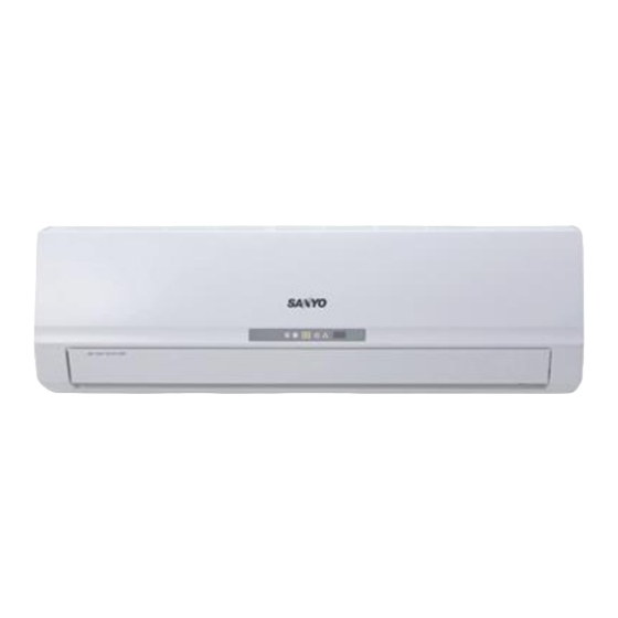
- Page 2 INSTRUCTION MANUAL Split System Air Conditioner INDOOOR UNIT OUTDOOR UNIT COOL / DRY MODEL SAP-K18AM / AMS SAP-C18AM / AMS HEAT PUMP MODEL SAP-K18AGH SAP-C18AGH Save These Instructions! Pub. OI-85264181002000 © SANYO 2010 SANYO Electric Co., Ltd.
-
Page 3: Table Of Contents
____ Date of purchase _______________________________________ Dealer’s addres _______________________________________ Phone number _________________ Thank you for choosing SANYO air conditioner, please read this instruction manual carefully before operating the unit and keep it carefully for consultation. Alert Symbols The following symbols used in this manual, alert you to... -
Page 4: Operation And Maintenance
The wrong repair will lead to an each wire to the gas pipe,water electric shock or fire, so you pipe, drainage pipe or any other should contact the SANYO It can help to preclude the improper places. service center for repair. - Page 5 Operation and Maintenance 1. NOTICES FOR OPERATION Do not use the air conditioner for other Do not place a space heater near the air purposes,such as drying clothes, conditioner. CO toxicosis may occur as preserving foods, etc. a result of imcomplete burning. Do not insert your hands or stick into Do not blow the wind to animals and the air intake or outlet vents.
-
Page 6: Notices For User
Operation and Maintenance 2. NOTICES FOR USER Principle: 2.1 Working Principle Air conditioner absorbs heat in the room and transmit to and Special outdoor and discharged, so that indoor ambient temperature Functions for decreased. It's cooling capacity will decrease by the increase Cooling of outdoor ambient temperature. - Page 7 Operation and Maintenance 2. NOTICES FOR USER 2.3 Working Temperature Range Temperature Indoor air temperature Outdoor air temperature Max. °C DB / 23 °C DB °C DB / 26 °C DB COOLING Min. °C DB / 15 °C DB °C DB / --- Max.
-
Page 8: Names And Functions Of Each Part
Operation and Maintenance 3. NAMES AND FUCTIONS OF EACH PART Indoor Unit Air intake Back side of part (4) *(5) x 2pcs (10) Air outlet (7) (8) The pattern in displayer: Wireless remote control :Cool :Dry :Fan :Heat :Run S/n Part Name :Set temp. -
Page 9: Operation Of Wireless Remote Control Unit
Operation and Maintenance 4. OPERATION OF WIRELESS REMOTE CONTROL UNIT 4.1 Remote Control Unit (Display) Displayed when transmitting data Displayed when setting temperature Displayed the clock Displayed when setting timer Symbols (1) Operation mode (4) Timer 24-hour ON Timer ..AUTO ...... - Page 10 Operation and Maintenance 4. OPERATION OF WIRELESS REMOTE CONTROL UNIT 4.2 Remote Control Unit (Functions) Signal Transmitter Display ON/OFF operation button MODE operation button TEMP. setting button TEMP button FAN SPEED Selector button SWING button CLOCK button TIMER ON button BLOW button TIMER OFF button TURBO button...
- Page 11 Operation and Maintenance 4. OPERATION OF WIRELESS REMOTE CONTROL UNIT 4.2 Remote Control Unit Functions (Continued) FAN SPEED selector AUTO : The air conditioner automatically decides the fan speeds. button : Low fan speed. : Medium fan speed. : High fan speed. AUTO TEMP button Press to see set temperature or indoor temperature which show on...
- Page 12 Operation and Maintenance 4. OPERATION OF WIRELESS REMOTE CONTROL UNIT 4.3 Using the General Operation STEP 1 STEP 2 STEP 3 STEP 5 STEP 4 NOTE Press the setting buttons as described below and change the settings as desired. STEP 1 To start the air conditioner, press the ON/OFF operation button.
- Page 13 Operation and Maintenance 4. OPERATION OF WIRELESS REMOTE CONTROL UNIT 4.4 Using the 24-Hour “ON” or “OFF” Timer 4.4.1 TIMER ON mode After the length of time set for TIMER ON elapses, the unit begins operating. (Example) The display depicted at left indicates that the air conditioner will begin operating in 10 hours.
- Page 14 Operation and Maintenance 4. OPERATION OF WIRELESS REMOTE CONTROL UNIT 4.5 Using the SLEEP Operation SLEEP Mode is used for saving energy. Press the SLEEP button while operation. mark appears in the display. To release the SLEEP function, press the SLEEP button again.
- Page 15 Operation and Maintenance 4. OPERATION OF WIRELESS REMOTE CONTROL UNIT 4.6 Using of the “SPECIAL” Features & Remarks “DRY” • During DRY operation, the fan speed is automatically set to Operation LOW. • If the room temp. is 2 °C higher than the Set Temperature, the How it works? unit will run in COOL mode.
- Page 16 Operation and Maintenance 4. OPERATION OF WIRELESS REMOTE CONTROL UNIT 4.6 Using of the “SPECIAL” Features & Remarks (Continued) About swing up and down “SWING” 1. Press swing up and down button continuously more than 2s, Operation the main unit will swing back and forth from up to down, and How it works? then loosen the button, the unit will stop swinging and present position of guide louver will be kept immediately.
- Page 17 Operation and Maintenance 4. OPERATION OF WIRELESS REMOTE CONTROL UNIT 4.7 How to Install Batteries 1. Slightly to press the place with , along the arrowhead direction to push the back cover of wireless remote control. (Fig. 1) 2. Take out the old batteries. (Fig. 1) 3.
-
Page 18: Clean And Care
Operation and Maintenance 5. CLEAN AND CARE CAUTION 1. For safety, be sure to turn the air conditioner off and also disconnect the power before cleaning. Or it may cause electric shock. 2. Never sprinkle water on the indoor unit and the outdoor unit for cleaning because it can cause an electric shock. - Page 19 Operation and Maintenance 5. CLEAN AND CARE 5.2 Cleaning the Air Filters (Continued) 1. Take Down the Air Filters Pull out the panel to an angle at botttom grooves on panel. And, pull the air filter upward then downward to take it off. (Fig. 7). 2.
-
Page 20: Troubleshooting
Solution : Clean the air filters (see Pg.16). If the problem still has, the unit required servicing. Hence, please contact with SANYO authorized maintenance center. Sound of water flow can be heard during Sometimes there is swoosh, or gurgle while operation. - Page 21 Operation and Maintenance 6. TROUBLESHOOTING The unit can not operate. • Has the power been shut down? • Is the power plug loosed? • Is voltage too high or too low? (tested by professional) • Has the TIMER ON function been well operated? Breaking off Cooling(Heating) efficiency is not good.
- Page 22 Operation and Maintenance 6. TROUBLESHOOTING Phenomenon Troubleshooting Indoor unit can't deliver air. • In HEAT “ ” mode, when indoor heat exchanger’s temperature is very low, to stop below the cool wind (within 3 mins). • In HEAT “ ” mode, when outdoor temp. is very low or high humidity, there are much frost on the outdoor heat exchanger, unit will automatically defrost, Indoor unit stop...
-
Page 23: Installation Service
3. When removing the unit to the other place, please firstly contact with the authorized SANYO Maintenance Center in the local area. 7.1 Basic Requirements Install in the following place may cause malfunction. If it... - Page 24 Installation Service 7. NOTICES FOR INSTALLATION 6. Make sure that the outdoor unit installation dimension 7.3 Outdoor Unit should accord with installation dimension diagram, Installation Position convenient for maintenance, repair. ( See Pg.23) Selection 7. The height difference of connecting the tubing within 5m, (Continued) the length of connecting the tubing within 10m.
-
Page 25: Installation Dimension Diagram
Installation Service 8. INSTALLATION DIENSION DIAGRAM Space to the ceiling 15cm Above Space to the wall 15cm Above 15cm Above Space to the wall 300cm Above Above Air outlet side Space to the floor • The dimensions of the space necessary for correct installation of the appliance including the minimum permissible distances to adjacent structures. -
Page 26: Install Indoor Unit
Installation Service 9. INSTALL INDOOR UNIT 9.1 Install the Real Panel 1. Always mount the rear panel Mark on the Wall Wall Gradienter horizontally. Due to the water tray middle of it of indoor unit has been adopted the Space Space to the to the... - Page 27 Installation Service 9. INSTALL INDOOR UNIT 9.4 Connect Indoor and Outdoor Electric Wire Power Supply Wire (1.8m) 1. The power wire and power connection wire are supplied in factory in a fixed length. (Fig.15a, 15b) NOTE Do consult your local dealer if additional wire length is required.
- Page 28 Installation Service 9. INSTALL INDOOR UNIT 9.4.2 Wire Length and Diameter Regulations on wiring diameter differ from locality. For field wiring requirements, please refer to local electrical codes. Carefully observe these regulations when carrrying out the installation. Table 1 lists the recommended and max. allowable wire lengths and diameters for the power supply system.
-
Page 29: How To Install The Indoor Unit
Installation Service 9. INSTALL INDOOR UNIT 9.5 How to Install the Indoor Unit For tubing, choose either the left side or right side direction. Tailing 2 Tailing 1 1. When routing the piping and wiring from the left or right side of indoor unit, cut off the Fig.20 tailing from the chassis in necessary. -
Page 30: Install Outdoor Unit
Installation Service 10. INSTALL OUTDOOR UNIT 10.1 Wiring Instructions for the Outdoor Unit Regulations on wire size differ from locality. For field wiring requirements, please refer to (Cooling Only Model ) Handle your local electrical codes. Make sure that the installation fully complies with all local and national regulations. - Page 31 Installation Service 10. INSTALL OUTDOOR UNIT 10.2 Refrigerant Tubing Deburring 10.2.1 Use of The Flaring Method Before After Many of the conventional split system air conditioners employ the flaring method to connect refrigerant tubes which run between indoor and outdoor units. In this method, the copper tubes are flared at each end and connected with flares nuts.
- Page 32 Installation Service 10. INSTALL OUTDOOR UNIT 10.2.4 Connecting Tubing between Indoor and Torque wrench Outdoor Units • Tightly connect the indoor side refrigerant tubing extended from the wall with the outdoor Spanner side tubing. (Fig. 30) Indoor unit • To fasten the flare nuts, apply specified torque Outdoor unit Table 2 Tube Dia.
- Page 33 Installation Service 10. INSTALL OUTDOOR UNIT 10.3 Air Purging Air and moisture remaining in the refrigerant Indoor unit system have undersirable effects as indicated below. Therefore, they must be purged completely. • Pressure in the system rises • Operating current rises •...
- Page 34 Installation Service 10. INSTALL OUTDOOR UNIT 10.3 Air Purging - (Continued) 5. With the vacuum pump still running, close the "Low" knob of the manifold valve. Then 90 (1/4 turn) Narrow tube stop the vacuum pump. 6. With the accessory hex wrench, turn the Hex wrench valve stem on the narrow tube service valve counter-clockwise by 90 degrees (1/4 turn)
-
Page 35: Tubing Length
Installation Service 10. INSTALL OUTDOOR UNIT 10.4 Tubing Length Install unit within the maximum elevation Tubing length (L) INDOOR different (H) above or below the outdoor UNIT unit and within a tatal tubing length (L) from the outdoor unit as detailed showed in Table 4 and Fig.37. -
Page 36: Pump Down
Installation Service 11. PUMP DOWN 11.1 What is Pump Down? Pump down means collecting all refrigerant gas in system back into the outdoor unit without losing any of gas. Pump down is used when the unit is to be moved or before serving the Indoor unit refrigerant circuit. -
Page 37: Check After Installation And Test Operation
Installation Service 12. CHECK AFTER INSTALLATION AND TEST RUN 12.1 Check After Installation Check the items listed in below table after installation of air conditioner. Items to be checked Possible malfunction • Has it been fixed firmly? • The unit may drop, shake or emit noise. •...