KitchenAid KFGS306VSS Technical Education
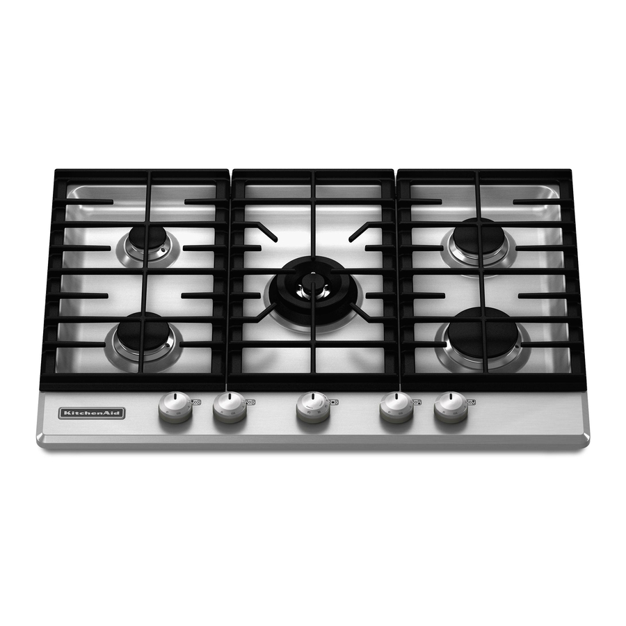
Flush-mount gas cooktop
Hide thumbs
Also See for KFGS306VSS:
- Dimension manual (1 page) ,
- Use & care manual (24 pages) ,
- Installation instructions manual (20 pages)

Related Manuals for KitchenAid KFGS306VSS


Summary of Contents for KitchenAid KFGS306VSS
-
Page 1: Gas Cooktop
KAC-51 TECHNICAL EDUCATION FLUSH-MOUNT GAS COOKTOP MODELS: KFGS306VSS, KFGU706VSS, KFGS366VSS, KFGU766VSS JOB AID 4317428... - Page 2 FORWARD This KitchenAid Job Aid “Flush-Mount Gas Cooktop” (Part No. 4317428), provides the In-Home Service Professional with information on the installation, operation, and service of the Flush-Mount Gas Cooktop. For specific information on the model being serviced, refer to the “Use and Care Guide,”...
-
Page 3: Table Of Contents
TABLE OF CONTENTS Page GENERAL ..........................1-1 Cooktop Safety........................1-1 Model & Serial Number Designations ................1-2 Model & Serial Number Label And Tech Sheet Locations ..........1-3 Specifications ........................1-4 INSTALLATION INFORMATION .................... 2-1 LP Gas And High Altitude Conversion Instructions ............2-11 PRODUCT OPERATION ....................... - Page 4 — NOTES — - iv -...
-
Page 5: General
GENERAL COOKTOP SAFETY Your safety and the safety of others are very important. We have provided many important safety messages in this manual and on the appliance. Always read and obey all safety messages. This is the safety alert symbol. This symbol alerts you to potential hazards that can kill or hurt you and others. -
Page 6: Model & Serial Number Designations
KITCHENAID MODEL & SERIAL NUMBER DESIGNATIONS MODEL NUMBER MODEL NUMBER S 30 PRODUCT GROUP K = KITCHENAID PRODUCT IDENTIFICATION EC = ELECTRIC COOKTOP GC = GAS COOKTOP IC = ELECTRIC INDUCTION COOKTOP FG = FLUSH GAS COOKTOP ED = ELECTRIC DOWNDRAFT COOKTOP... -
Page 7: Model & Serial Number Label And Tech Sheet Locations
MODEL & SERIAL NUMBER LABEL AND TECH SHEET LOCATIONS The Model/Serial Number label and Tech Sheet locations are shown below. Tech Sheet Location (On Inside Of Cooktop) Model/Serial Number Location (On Bottom Of Cooktop) -
Page 8: Specifications
SPECIFICATIONS 30” 36” Superba Ultima Superba Ultima Model Number KFGS306VSS KFGU706VSS KFGS366VSS KFGU766VSS Canadian Model Number KFGS306VSS KFGU706VSS KFGS366VSS KFGU766VSS Colors Installs Over Undercounter Oven Agency Ratings Electric Supply 120 VAC, 60 120 VAC, 60 120 VAC, 60 120 VAC, 60... - Page 9 CONTROLS Location Front Front Front Front Removable Dials/Knobs Metal Puck Metal Puck Metal Puck Metal Puck Lock Out Hot Indicator Light Control Graphics Etched Serigraphy on Etched Serigraphy on glass glass DIMENSIONS - IN. (CM) Exterior Dimensions Overall Height (in) Overall Width (in) 30 1/4”...
- Page 10 — NOTES —...
-
Page 11: Installation Information
INSTALLATION INFORMATION INSTALLATION REQUIREMENTS TOOLS AND PARTS Gather the required tools and parts before start- ing installation. Read and follow the instructions provided with any tools listed here. Tools needed • Tape measure • Flat-blade screwdriver • 3/32" (#0 [2 mm]) flat blade screwdriver (screwdriver shaft must be a minimum of 1 1/8"... -
Page 12: Product Dimensions
• Provide cutout in right rear corner of cutout I. 29" (73.7 cm) on 30" (76.2 cm) models; 35¼" (89.5 cm) on 36" (91.4 cm) models enclosure as shown to provide clearance for J. 24" (61.0 cm) minimum countertop depth is required gas inlet, power supply cord, and to allow the �⁄�... -
Page 13: Gas Supply Requirements
IMPORTANT: The cooktop must be electrically GAS SUPPLY REQUIREMENTS grounded in accordance with local codes and ordinances, or in the absence of local codes, with the National Electrical Code, ANSI/NFPA 70 or Canadian Electrical Code, CSA C22.1. If codes permit and a separate ground wire is used, it is recommended that a qualified elec- trical installer determine that the ground path is adequate. - Page 14 types of gas that can be used. If the types of gas listed do not include the type of gas available, check with the local gas supplier. LP Gas Conversion: Conversion must be done by a qualified service • Must include a shutoff valve: technician. The supply line must be equipped with a No attempt shall be made to convert the cook- manual shutoff valve.
-
Page 15: Install Cooktop
INSTALLATION REQUIREMENTS INSTALL COOKTOP The clamping brackets can be installed before or after the cooktop is placed into WARNING the cutout. Complete the following steps for the option you choose. Excessive Weight Hazard Installing Brackets Before Placing Cook- top in Cutout Use two or more people to move and install cooktop. -
Page 16: Make Gas Connection
NOTE: Make sure that the front edge of Attach brackets to cooktop base bottom the cooktop is parallel to the front edge of with bracket attachment screws using the the countertop. If repositioning is needed, bracket mounting holes selected in Step lift entire cooktop up from cutout to avoid 3. - Page 17 Use only pipe-joint compound made for use Complete Connection with Natural and LP gas. Open the manual shutoff valve in the gas Do not use TEFLON® tape. You will need to supply line. The valve is open when the determine the fittings required depending on handle is parallel to the gas pipe.
-
Page 18: Complete Installation
COMPLETE INSTALLATION WARNING Electronic Ignition System Initial lighting and gas flame adjustments Sur- face burners use electronic igniters in place of standing pilots. When the cooktop control knob is pushed in and turned to the “LITE” position, the system creates a spark to light the burner. Electrical Shock Hazard This sparking continues, as long as the control Plug into a grounded 3 prong outlet. - Page 19 Turn adjustment screw “C” to the right to reduce Adjust Flame Height flame height, turn adjustment screw to the left The surface burner “low” flame should be a to increase flame height. steady blue flame approximately 1/4" (0.64 cm) high. A. Low ame B. High ame �⁄�� " (#0 [2.0 mm]) at blade screwdriver (screwdriver shaft must be a minimum of �⁄�...
- Page 20 Remove the control knob. 12. Replace the control knob. Remove the black rubber grommet. 13. Test the flame by turning the control from LO to HI, checking the flame at each Using needle-nose pliers, remove the gray setting. shield inside the burner valve opening. If you need Assistance or Service: Please reference the “Assistance or Service” section of the Use and Care Guide or contact the dealer from whom you purchased your cooktop.
-
Page 21: Lp Gas And High Altitude Conversion Instructions
LP GAS AND HIGH ALTITUDE CONVERSION INSTRUCTIONS TOOLS AND PARTS Warning This conversion kit shall be installed Gather the required tools and parts necessary by a qualified service agency in ac- for correct LP gas conversion. cordance with the manufacturer's in- Tools needed structions and all applicable codes and •... - Page 22 To Convert Gas Pressure Regulator Explosion Hazard Use a new CSA International approved gas supply line. Install a shut-off valve. Securely tighten all gas connections. A. Access cap If connected to LP, have a qualified B. Rear of cooktop person make sure gas pressure does C.
-
Page 23: Gas Supply Pressure Testing
Style 2: The cap does not have a slot and Line pressure testing at ½ psi gauge (14" requires a wrench to be removed. WCP) or lower Remove the access cap by using a wrench, The cooktop must be isolated from the gas turning the access cap counterclockwise. -
Page 24: Burner Locations
High Altitude Conversions Remove all burner caps and burner bases. If necessary, remove the burner ring. IMPORTANT: You must convert LP gas with LP gas high altitude or Natural gas with Natu- ral gas high altitude. If you need to convert LP gas to Natural gas high altitude or Natural gas to LP gas high altitude you must convert the pressure regulator, for this you must follow... - Page 25 On all models, remove the metal cooktop and the sheet of insulation from the cooktop base. A. Ori ce D. First groove (12.0 mm natural gas setting) B. Venturi E. Venturi screw C. Second Groove (16.0 mm LP gas setting) •...
-
Page 26: Convert From Lp Gas To Natural Gas
IMPORTANT: The igniter electrode is ceramic The gas pressure regulator has 2 settings and could break during conversion. Be sure which are stamped on either side of the cap. that the electrode comes through the hole Turn the cap and reinstall into regulator with in the burner head smoothly while tightening the stamp “NAT”... - Page 27 Use the following charts to match the correct gas orifice spud with the burner location and Natural Gas Orifice Spud Chart for High Altitude Conversion model being converted. Burner Rating Stamp (A) Size 6,000 BTU 1.05 mm Natural Gas Orifice Spud Chart 7,000 BTU 1.18 mm Burner Rating...
- Page 28 8. To Convert Right or Left Burners: Using a T20 TORX® screwdriver, remove the orifice holder screws (C). • Insert 7.0 mm nut driver down onto the gas orifice spud and remove by turning it coun- terclockwise and lifting out. • Set gas orifice spud aside. • Replace with correct Natural gas orifice spud. See the Natural Gas Orifice Spud Charts. To Convert Center Burners: • Use 10.0 mm wrench to loosen and remove the orifice.
-
Page 29: Lighting The Electronic Igniters
Lighting the Electronic Igniters • Replace with correct Natural gas orifice spud. See Natural Gas Orifice Spud Charts. The cooktop burners use electronic igniters • Replace adapter nut and secure with 17.0 in place of standing pilots. When the cooktop mm wrench. Reattach tube and secure at- control knob is pushed, the system creates a tachment nut with 15.0 mm wrench. - Page 30 Flame Height Adjustment For Natural gas conversion: Each burner flame has been factory set to the Tighten screw “C” to reduce flame height. lowest position available to provide reliable and Loosen screw to increase flame height. See constant reignition of the burner; however, each “Complete Burner Adjustment” section. burner can be adjusted. Replace the control knob. To Adjust: 6. Test the flame by turning the control from The flame can be adjusted using the adjustment LO to HI, checking the flame at each screws underneath the control knob.
- Page 31 For LP gas conversion: Complete Burner Adjustment Completely tighten screw “A” to set the 1. Check burner flame(s) for proper size and minimum flame height. shape. The cooktop “low” burner flame For Natural gas conversion: should be a steady blue flame approxi- mately 1/4" (0.64 cm) high. Tighten screw “A” to reduce flame height. Loosen screw to increase flame height. See “Complete Burner Adjustment”...
- Page 32 — NOTES — 2-22...
-
Page 33: Product Operation
PRODUCT OPERATION Control Panel (Glass) A. Left rear burner control knob D. Hot surface indicator G. Right front burner control knob B. Surface burner locator E. Center burner control knob H. Right rear burner control knob C. Left front burner control knob F. -
Page 34: Hot Surface Indicator Light
Tones To Light: Tones are audible signals, indicating the 1. Push in and turn knob counterclockwise to LITE. All surface burners will click. Only the following: burner with the control knob turned to Lite One Long Beep will produce a flame. •... -
Page 35: Component Access
COMPONENT ACCESS This section instructs you on how to service each component inside the KitchenAid Flush-Mount Gas Cooktop. The components and their locations are shown below. COMPONENT LOCATIONS WARNING Electrical Shock Hazard Disconnect power before servicing. Replace all parts and panels before operating. -
Page 36: Removing The Cooktop
REMOVING THE COOKTOP WARNING Spreader Electrical Shock Hazard Spreader Bezel Disconnect power before servicing. Bezel Burner Grates Replace all parts and panels before operating. Failure to do so can result in death or electrical shock. NOTE: The electronic control is part of the cooktop and cannot be serviced separately. - Page 37 Lift the front of the cooktop just high enough to access the electronic control connector, and pull the wire connector off the connec- tor pins. (KFGU models only) Lift Cooktop Lift the cooktop off the burner box and remove it. Connector Lift the cooktop off the burner box and remove it.
-
Page 38: Removing The Spark Switches, And The Standard Or Crown Burner Gas Valves
REMOVING THE SPARK SWITCHES, AND THE STANDARD OR CROWN BURNER GAS VALVES b) Pull the spark switches off each of the WARNING standard gas valves. Pull the switches straight out from the valves to unclip and remove them. Standard Burner Electrical Shock Hazard Disconnect power before servicing. - Page 39 d) Unlatch and disconnect the main wire d) Remove the screw from the gas mani- connector from the spark switches and fold clamp and remove the gas valve. remove the switches. Spark Switch Connector To remove a standard gas valve: a) Remove the spark switch from the valve you are accessing (see step 3).
- Page 40 To remove the Crown burner gas valve: f) Remove the screw from the gas manifold clamp and remove the Crown burner a) Remove the spark switch from the Crown gas valve. burner gas valve (see step 3c). b) Remove the six screws from the front burner box access panel and remove the panel.
-
Page 41: Removing The Power Supply Transformer And The Spark Module
REMOVING THE POWER SUPPLY TRANSFORMER AND THE SPARK MODULE WARNING 5-Wire Connector 2-Wire Connector Electrical Shock Hazard Disconnect power before servicing. Replace all parts and panels before operating. Power Supply Transformer Failure to do so can result in death or electrical shock. -
Page 42: Removing The Gas Shutoff Valve
REMOVING THE GAS SHUTOFF VALVE WARNING Remove the burner assembly then 4 screws securing manifold pipe. Manifold Pipe Screws Electrical Shock Hazard Disconnect power before servicing. Replace all parts and panels before operating. Failure to do so can result in death or electrical shock. -
Page 43: Removing A Spark Ignitor From Standard Or Crown Burner
REMOVING A SPARK IGNITOR FROM STANDARD OR CROWN BURNER b) Remove igniter retainer clip from stan- WARNING dard burner. Electrical Shock Hazard Igniter Disconnect power before servicing. Replace all parts and panels before Igniter operating. Retainer Clip Failure to do so can result in death or electrical shock. - Page 44 To remove spark igniter from crown d) Lift crown burner up and rotate to ex- burner. pose two screws on back of mounting a) Disconnect spark ignitor wire from spark plate. module. e) Remove two screws from back of mounting plate attached to crown burner and remove mounting plate.
-
Page 45: Removing Standard Or Crown Burner
REMOVING STANDARD OR CROWN BURNER WARNING Hold Down Clamp Screw Mounting Screws Ground Screw Electrical Shock Hazard Disconnect power before servicing. Replace all parts and panels before Mounting Screws operating. c) Remove 4 mounting screws located on Failure to do so can result in death or outside of burner box holding burner electrical shock. - Page 46 g) Disconnect gas line fitting from standard Mounting Screws burner. h) Remove igniter from standard burner (see removing a spark igniter from standard or crown burner 4-9). i) Turn burner assembly upside down on protected surface. j) Remove 2 screws from bottom of standard burner attaching it to burner support.
-
Page 47: Removing The Power Supply Cord
REMOVING THE POWER SUPPLY CORD Remove the screw from the power supply WARNING cord ground wire. Press the locking tab on the power supply cord connector and disconnect it from the main connector. Remove the strain relief from the power supply cord and pull the cord out of the burner box mounting hole. - Page 48 — NOTES — 4-14...
-
Page 49: Component Testing
COMPONENT TESTING Before testing any of the components, perform • Check all connections before replacing the following checks: components, looking for broken or loose wires, failed terminals, or wires not pressed • The most common cause for control failure into connectors far enough. is corrosion on connectors. -
Page 50: Crown Burner Switch
WARNING Electrical Shock Hazard Disconnect power before servicing. Replace all parts and panels before operating. Failure to do so can result in death or electrical shock. CROWN BURNER SWITCH POWER SUPPLY TRANSFORMER Switch (N.O.) Primary Connector Refer to page 4-3 for the procedure for access- Refer to page 4-6 for the procedure for access- ing the Crown burner switch. -
Page 51: Diagnostics & Troubleshooting
DIAGNOSTICS & TROUBLESHOOTING WARNING Electrical Shock Hazard Disconnect power before servicing. Replace all parts and panels before operating. Failure to do so can result in death or electrical shock. DIAGNOSTICS IMPORTANT Disconnect power and perform the following Electrostatic Discharge (ESD) checks: Sensitive Electronics •... -
Page 52: Troubleshooting
TROUBLESHOOTING Appliance operates correctly but one or more User Interface indicators do not operate POTENTIAL CAUSES ACTION 1.1.1 Bad connections Check wiring between User Interface and UI connector on the igniter module between igniter module 1.1.2 Check the User Interface connectors on the igniter module and User Interface are &... - Page 53 Turn on a single Burner and the associated User Interface lamp illuminates. No sparking is evident at the spark gaps of any Burner. The associated click when sparking cannot be heard. No gas flows while the burner is on. Turning on one other or more Burner results in sparking at all Burners and ignition of the selected burners POTENTIAL CAUSES ACTION...
- Page 54 No ignition when a particular Burner is turned on. Sparking is either evident at the Burner's spark gap or the associated clicking can be heard POTENTIAL CAUSES ACTION No gas flow or poor gas 5.1.1 Check gas flows to appliance flow in the vicinity of the Check operation of the Gas Solenoid in series with gas manifold.
- Page 55 Intermittent sparking following ignition on any activated burner. POTENTIAL CAUSES ACTION Air drafts alter the flame shape pushing the 7.1.1 Check surrounding environment for excessive drafts and minimize large drafts. flame away from electrode. Momentary loss of flame occurs and sparking is initiated until flame is sensed again.
- Page 56 TRANSFORMER TABLE Primary Coil 60 ± 6 Ω 22 °C Resistance Secondary Coil Rs 1-2 4.7 ± 0.5 Ω 22 °C Resistance Secondary Coil Rs 2-3 4.7 ± 0.5 Ω 22 °C Resistance Secondary Coil Rs 4-5 306 ± 30 Ω...
-
Page 57: Wiring Diagram & Strip Circuit
WIRING DIAGRAM & STRIP CIRCUIT CONTROL POWER INDICATOR CENTER POWER ON INDICATOR SEE OPERATION DIAGRAM 1 & 2 CONTROL LOCK SURFACE HOLD FOR 5 SEC 0° 0° 15°±10° 230° 230° 165°±10° SWITCH ELECTRIC CONTACTS CLOSED SWITCH ELECTRIC CONTACTS CLOSED OPERATION DIAGRAM 1 OPERATION DIAGRAM 2 ELECTRONIC CONTROL STRIP CIRCUIT P2-10... -
Page 58: Wiring Diagram
WIRING DIAGRAM ELECTRONIC CONTROL WIRING DIAGRAM SYMBOLS GROUND (CHASSIS) TRANSFORMER PLUG WITH FEMALE RELAY CONTACTS CONNECTOR RECEPTACLE WITH MALE CONNECTOR SOLENOID VALVE ELECTRODE SWITCH POWER CONTROL CONNECTION COMMUNICATION ELECTRODES OUTPUT... -
Page 59: Product Specifications
WARRANTY INFORMATION SOURCES IN THE UNITED STATES: FOR PRODUCT SPECIFICATIONS AND WARRANTY INFORMATION CALL: FOR WHIRLPOOL PRODUCTS: 1-800-253-1301 FOR KITCHENAID PRODUCTS: 1-800-422-1230 FOR ROPER PRODUCTS: 1-800-447-6737 FOR TECHNICAL ASSISTANCE WHILE AT THE CUSTOMER’S HOME CALL: THE TECHNICAL ASSISTANCE LINE: 1-800-832-7174...