
Related Manuals for Rheem 325


Summary of Contents for Rheem 325
-
Page 1: Owners Guide
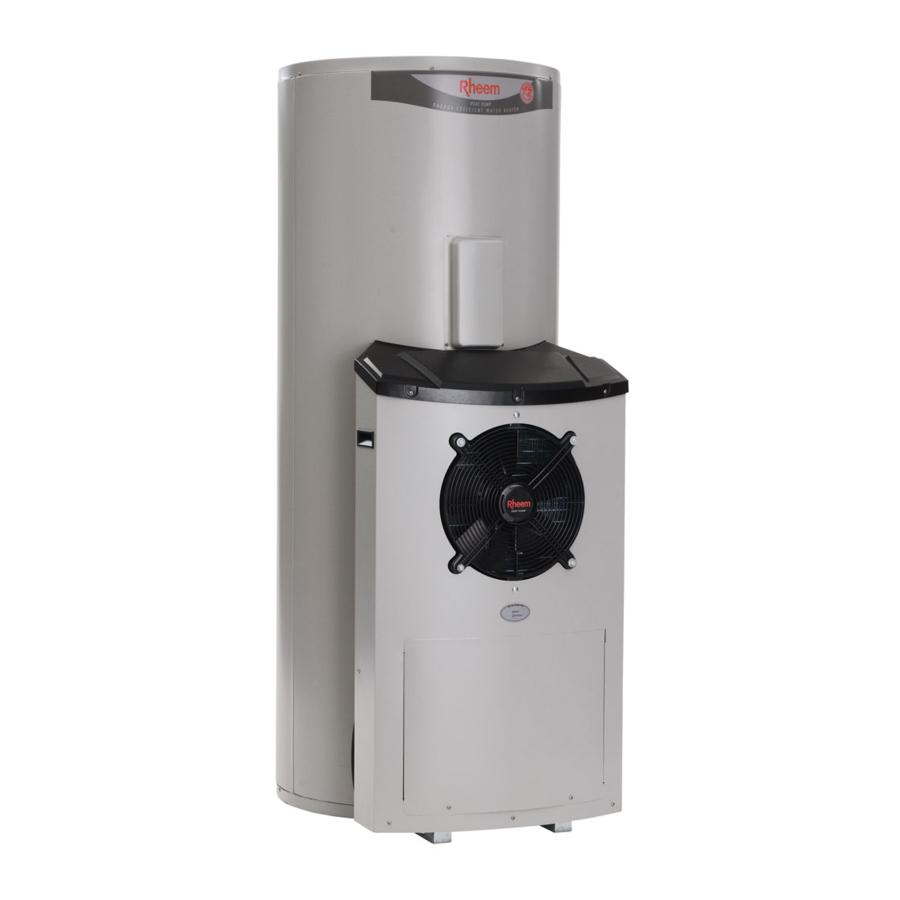
Owners Guide Installation Instructions Air Sourced 325 Heat Pump Water Heater This water heater must be installed and serviced by an authorised person. Please leave this guide with the householder. - Page 2 This water heater may be protected by one or more patents or registered designs in the name of Rheem Australia Pty Ltd. TRADE MARKS ® Registered trademark of Rheem Australia Pty Ltd. ™ Trademark of Rheem Australia Pty Ltd. Note: Every care has been taken to ensure accuracy in preparation of this publication.
-
Page 3: Table Of Contents
CONTENTS HOUSEHOLDER – We recommend you read pages 4 to 14. The other pages are intended for the installer but may be of interest. About Your Water Heater ......................4 Regular Care ..........................8 Water Supplies..........................9 Save A Service Call ........................12 Installation .......................... -
Page 4: About Your Water Heater
Rheemglas model. The Rheem air sourced heat pump water heater has a vitreous enamel lined steel cylinder. The water heater‟s evaporator absorbs heat from the surrounding air and transfers this heat into the water. When hot water is drawn off and cold water enters the tank, the thermostat activates a fan, a compressor and a circulator. - Page 5 If the electrical supply conduit to the water heater is damaged, it must be replaced by an authorised person in order to avoid a hazard. Phone your nearest Rheem Service Department or Accredited Service Agent to arrange for an inspection.
- Page 6 The heat pump will then return to normal operation and the green LED will commence operating. If the red LED continues or recommences to flash, count the number of flashes and phone your nearest Rheem Service Department or Accredited Service Agent to arrange for an inspection.
- Page 7 At the end of the service life of the heat pump water heater and prior to the water heater being disposed of, a person qualified to work with refrigerants must recover the refrigerant from within the sealed system. The refrigerant must not be vented to atmosphere. Phone your nearest Rheem Service Department or Accredited Service Agent to arrange for an inspection.
-
Page 8: Regular Care
If water does not flow freely from the drain line when the lever is lifted, then the water heater should be checked by your nearest Rheem Service Department or Accredited Service Agent. The temperature pressure relief valve should be checked for... -
Page 9: Water Supplies
Water heaters must be installed in accordance with this advice to be covered by the warranty. A Rheem water heater is manufactured to suit the water conditions of most public reticulated water supplies. However, there are some known water supplies which can have detrimental effects on the water heater and its operation and/or life expectancy. - Page 10 A low watts density heating unit must be used. Water with an SI greater than +0.80 may be treated with a water softening device to reduce the SI of the water. Contact your nearest Rheem Service Department or Accredited Service Agent if a replacement heating unit is required.
- Page 11 -1.0 +0.4 +0.8 WATER SUPPLIES SATURATION INDEX (measured @ 80°C water temperature) WATER CHEMISTRY CHARTS corrosive scaling TOTAL DISSOLVED SOLIDS & CONDUCTIVITY NO WARRANTY APPLIES warranty applies to a vitreous enamel lined water heater cylinder if the to a vitreous correct coloured anode is used for the TDS / conductivity level of water SATURATION INDEX (SI) enamel lined...
-
Page 12: Save A Service Call
100 litres. “Heat Pump Is Not Operating” Refer to on page 13. Phone your nearest Rheem Service Department or Accredited Service Agent to arrange for an inspection. Temperature pressure relief valve running Is the relief valve discharging too much water? “Temperature Pressure Relief Valve Running”... - Page 13 If the water is being heated to 70°C, the ambient air temperature has not fallen below 3°C to 5 °C, the heat pump has not been operating and the red LED is flashing, phone your nearest Rheem Service Department or Accredited Service Agent to arrange for an inspection.
- Page 14 Heavy flows of hot water until the water heater is cold - then stops until water reheats The water heater must be switched off at the isolating switch or switchboard. Phone your nearest Rheem Service Department or Accredited Service Agent to arrange for an inspection. HIGH ELECTRICITY BILLS With the installation of your new air sourced heat pump water heater, maximum electrical energy savings can be achieved.
-
Page 15: Installation
INSTALLATION THIS WATER HEATER IS FOR OUTDOOR INSTALLATON ONLY. THIS WATER HEATER IS NOT SUITABLE FOR POOL HEATING. STORAGE TANK AND HEAT PUMP MODULE The heat pump water heater is made of two main components, the storage tank and the heat pump module. For transport and handling (weight) purposes both items are shipped separately and designed to be assembled at the installation site. - Page 16 INSTALLATION MAINS WATER SUPPLY Where the mains water supply pressure exceeds that shown in the table below, an approved pressure limiting valve is required and should be fitted as shown in the installation diagram (refer to diagram on page 31). Model Relief valve setting 1000 kPa...
- Page 17 INSTALLATION HOT WATER DELIVERY This water heater can deliver water at temperatures which can cause scalding. It is necessary and we recommend that a temperature limiting device be fitted between the water heater and the hot water outlets in any ablution area such as a bathroom or ensuite, to reduce the risk of scalding. The installing plumber may have a legal obligation to ensure the installation of this water heater meets the delivery water temperature requirements of AS/NZS 3500.4 so that scalding water temperatures are not delivered to a bathroom, ensuite or other ablution area.
- Page 18 INSTALLATION CIRCULATED HOT WATER FLOW AND RETURN SYSTEM A heat pump water heater should not be installed as part of a circulated hot water flow and return system in a building. If a circulated flow and return system is required, it is necessary to bypass the heat pump water heater and install a secondary water heater connected to the hot water flow and return line and supplied from the heat pump water heater.
- Page 19 INSTALLATION REDUCING HEAT LOSSES The cold water line to and the hot water line from the water heater must be insulated in accordance with the requirements of AS/NZS 3500.4. The insulation must be weatherproof and UV resistant if exposed. ANODE TYPES The vitreous enamel lined cylinder of this water heater is covered by warranty where the total dissolved solids (TDS) content in the water is less than 2500 mg/L and when the correct colour coded anode is used.
- Page 20 INSTALLATION TYPICAL INSTALLATON – OUTDOOR LOCATION TYPICAL INSTALLATION HEAT PUMP WATER HEATER - 325L...
- Page 21 INLET System number 551 325 Part numbers HEAT PUMP DIMENSIONS - 325L Model number 2.4 kW 551 325 05 Tank only 2.4 kW T551 325 05 3.6 kW 551 325 07 Tank only 3.6 kW T551 325 07 Heat pump module...
-
Page 22: Heat Pump And Tank Assembly
HEAT PUMP AND TANK ASSEMBLY STORAGE TANK AND HEAT PUMP MODULE The heat pump water heater is made of two main components, the storage tank and the heat pump module. For transport and handling (weight) purposes both items are shipped separately and designed to be assembled at the installation site. - Page 23 HEAT PUMP AND TANK ASSEMBLY ASSEMBLY PROCEDURE Warning: The heat pump must be assembled, plumbed and filled with water prior to power being connected and switched on. The following procedure should be followed to properly place the heat pump module in position and connect to the storage tank: Remove all packaging and position the storage tank in its intended location.
- Page 24 HEAT PUMP AND TANK ASSEMBLY Connect the mains power supply wiring to the terminal block and earth connection inside of the lower front cover. Secure the conduit to the side of the storage tank with a saddle clamp. The saddle clamp must be positioned over the pilot holes provided, otherwise the conduit will interfere with the heat pump module installation.
- Page 25 HEAT PUMP AND TANK ASSEMBLY Retrieve the drain pipe kit from inside of the heat pump module. Feed the hose through the penetration on the side of the heat pump module Slip the hose clamp over the upper end of the hose within the heat pump module ...
- Page 26 HEAT PUMP AND TANK ASSEMBLY Retrieve the loose ends of the two flexible braided hoses from within the heat pump module. Attach the flexible braided hose from the bottom of the heat exchanger and marked “INLET” in blue on its connection, to the bottom connection on the storage tank. Tighten the swivel nut on the hose using a 24 mm spanner.
- Page 27 HEAT PUMP AND TANK ASSEMBLY Remove the tab on the side of the electrical entry to the heat pump module to accommodate the electrical conduit. Pliers or tin snips may be required to remove the tab. Step 15 remove the tab on the side of the electrical entry to the heat pump module Retrieve the three (3) brass studs from the kit and screw into the three (3) threaded inserts on the side of the tank closest to the wall.
- Page 28 HEAT PUMP AND TANK ASSEMBLY Position the heat pump module against the tank. Engage the tab at the bottom of the heat pump module, on the wall side of the module, into the slot in the tank. Align the holes in the side of the heat pump module over the three brass studs. ...
- Page 29 HEAT PUMP AND TANK ASSEMBLY Insert the tank sensor cable plug to the connector on the underside of the control box. The plug is polarised and can only be inserted one way. Ensure the plug fully engages the locking feature on the connector. ...
- Page 30 HEAT PUMP AND TANK ASSEMBLY Turn on the cold water supply and fill the water heater. Check for leaks at the inlet and outlet connection points and at the connection points for the flexible braided hoses. “To Fill And Turn On The Water Heater” Refer to on page 35, however the electrical supply should not be turned on at this stage.
-
Page 31: Connections - Plumbing
CONNECTIONS – PLUMBING CONNECTION SIZES Hot water connection: RP¾/20. Cold water connection: RP¾/20. Relief valve connection: RP½/15. All plumbing work must be carried out by a qualified person and in accordance with the Plumbing Standard AS/NZS 3500.4 and local authority requirements. ... - Page 32 CONNECTIONS – PLUMBING EXPANSION CONTROL VALVE Local regulations may make it mandatory to install an expansion control valve (ECV) in the cold water line to the water heater. In other areas, an ECV is required if the saturation index is greater than +0.4 (refer to “Water Supplies”...
-
Page 33: Connections - Electrical
CONNECTIONS – ELECTRICAL The power supply to the water heater must not be switched on until the water heater is filled with water and a satisfactory megger reading is obtained. MEGGER READING When a megger test is conducted on this water heater, then the following should be noted. Warning: This water heater contains electronic equipment and 500 V insulation tests must only be conducted between active and earth and between neutral and earth. -
Page 34: Wiring Diagram
CONNECTIONS – ELECTRICAL WIRING DIAGRAM THERMOSTAT BLUE COMPRESSOR LIGHT RED CAPACITOR CONTROL BLUE BOARD BLACK COMP-N COMP-A GREEN/YELLOW FAN-N FAN-A COMPRESSOR PUMP-N PUMP-A COMPRESSOR HEATER NEUTRAL PLUG ELEMENT BLACK NC NO EARTH BROWN BLUE BLUE BLACK GREEN/YELLOW GREEN/YELLOW T2 - Compressor Thermistor FAN PLUG T1 - Evaporator Thermistor CAPACITOR... -
Page 35: Commissioning
COMMISSIONING TO FILL AND TURN ON THE WATER HEATER The power supply to the water heater must not be switched on until the water heater is filled with water and a satisfactory megger reading is obtained. Open all of the hot water taps in the house (don‟t forget the shower). Open the cold water isolation valve fully to the water heater. -
Page 36: Diagnostic Features Of Heat Pump Controller
The heat pump will then return to normal operation and the green LED will commence operating. If the red LED continues or recommences to flash, count the number of flashes and phone your nearest Rheem Service Department or Accredited Service Agent to arrange for an inspection. -
Page 37: Draining The Water Heater
DRAINING THE WATER HEATER To drain the water heater: “To Turn Off The Water Heater” Turn off the water heater (refer to on page 35). Close all hot water taps. Operate the relief valve release lever - do not let the lever snap back or you will damage the valve seat. Operating the lever will release the pressure in the water heater. - Page 38 This page is intentionally blank.