Table of Contents
Advertisement
Advertisement
Table of Contents

Related Manuals for Sekonic FLASH MASTER L-358


Summary of Contents for Sekonic FLASH MASTER L-358
- Page 2 But since you will never use them all at the same time, once you have learned all about it, it is simple and its use will become second nature. The Flash Master L-358 has undergone extensive quality controls at every step of manufacture. Please read this instruction manual thoroughly, to be able to take advantage of its many features and to obtain the long service life it is designed for.
-
Page 3: Table Of Contents
Table of Contents Parts Designation ........................ 1 Explanation of the Liquid Crystal Display (LCD) ..............2-3 Before Using ........................4-6 Attach the strap ......................4 Inserting the battery ....................4 Checking battery capacity ..................4 Replacing battery during measurement or when using the memory function ................5 Auto Power Off function ..................... -
Page 4: Parts Designation
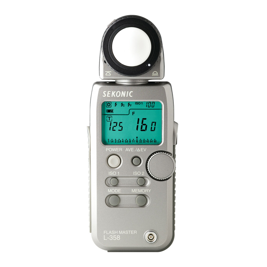
1. Parts Designation q Lumisphere retracting ring !4 Lock lever w Lumisphere e Liquid Crystal Display (LCD) !3 Mini light receptor r Average / outlet EV (Brightness Difference) button t Jog wheel !2 Power button (ON/OFF switch) y ISO 2 button ! 1 ISO 1 button u Memory button ! 0 Mode set button... -
Page 5: Explanation Of The Liquid Crystal Display (Lcd)
2. Explanation of the Liquid Crystal Display NOTE: For explanation purposes, the display illustrated here shows all icons and readouts simultaneously. Actual display will never show as above. Auto Electro-Luminescent Display (EL) In low light (EV 6 or less), a green backlight will automatically illuminate the entire LCD. When using the Mini Light Receptor or a Booster (optional accessories) the LCD will be illuminated after measuring, regardless of the ambient light level. - Page 6 2. Explanation of the Liquid Crystal Display q Measuring Mode Icons Ambient (see page 11) Auto-Reset Cordless Flash (see page 17) Cord Flash (see page 15) Wireless flash radio triggering mode (see page 30) w ISO Display Displays ISO film setting Displays second ISO film setting when ISO 2 button is depressed e Flash Analyzing indicator 0 % to 100% in 10% increments (percentage of flash in the total exposure)
-
Page 7: Before Using
3. Before Using Attach the strap Attach the Strap @1 by passing the small end loop through the eyelet o and passing the other end of strap through it. WARNING • Please place in a location where an infant cannot reach and accidentally get the strap wrapped around his neck. -
Page 8: Replacing Battery During Measurement Or When Using The Memory Function
3. Before Using Replacing battery during measurement or when using the memory function Always turn the power OFF before replacing batteries. If batteries are removed with the power ON, measurements and settings in memory can no longer be recalled. If after replacing the battery, or during measurements, strange screens (displays that have not been set) appear in the LCD, or nothing happens, no matter what button is pushed, remove the battery and wait at least ten seconds and then replace the battery. -
Page 9: Mesurement Lock And Measurement Lock Off
3. Before Using Mesurement Lock and Measurement Lock Off 1. Hold down the Mode set button !0 and ISO1 button !1 and "LOC" will appear to indicate that the settings are locked. The last measurement is held until the lock is released, even if the Jog wheel t is accidentally moved. -
Page 10: Basic Operation
4. Basic Operation Setting measuring mode Hold down the Mode set button ! 0 and turn the Jog wheel t to select the desired mode. The mode switching sequence is shown in the chart below: MODE with Radio Shutter speed priority Wireless Multiple Flash transmitter module mode (Ambient light) -
Page 11: Setting Dip Switches
4. Basic Operation Setting DIP Switches Switches for setting modes that are used infrequently are housed in the Battery compartment of the meter. Select the mode you want prior to beginning measurements. The DIP switches can be set by sliding the DIP switch !8 for the mode you want to select in the ON position. -
Page 12: When Set For Incident Light
4. Basic Operation When set for incident light Incident light measurements can be performed with the lumisphere fully extended or in the retracted position. You can switch between Lumisphere in the up position or retracted position by firmly rotating the Lumisphere retracting ring q until it clicks. Lumisphere Retracted Lumisphere When the Lumisphere is raised... -
Page 13: When Set For Reflected Light (Spot Metering)
4. Basic Operation When set for reflected light • This method measures the brightness (luminance) of the light reflected from the subject. It is useful for distant objects such as landscapes, when you cannot go to the position of the subject, or for metering subjects that generate light (neon signs, etc.), highly reflective surfaces or translucent subjects (stained glass, etc.). -
Page 14: Measurment
5. Measurement Measuring ambient light In this measurement mode, we have the choice of shutter priority mode, aperture priority mode and EV mode. Hold down the Mode set button !0 and turn the Jog wheel t to select ambient measurement mode 1-1 Shutter Speed Priority mode Hold down the Mode set button and turn the Jog... -
Page 15: Aperture Priority Mode
5. Measurement 1-2 Aperture Priority mode 1. Hold down the Mode set button !0 and turn the Jog wheel t to select aperture priority mode 2. Turn the Jog wheel to set the desired f stop value. MODE Measured value (shutter speed) 3. -
Page 16: Ev Mode
5. Measurement 1-3 EV mode Open the Battery compartment cover !6 and slide the EV DIP switch (see page 8) to the ON position. 1. Hold down the Mode set button !0 and turn the Jog wheel t to select value mode. -
Page 17: Cinematography
5. Measurement 1-4 Cinematography 1. Hold down the Mode set button ! 0 and turn the Jog wheel t to select ambient light shutter speed priority mode MODE 2. Turn the Jog wheel t to select the Cine Speed for the camera that will be used. -
Page 18: Measuring Flash Light
5. Measurement Measuring flash light This method of measurement can be done in the following modes; with cord, without cord, multiple flash with cord, multiple flash without cord and Wireless flash radio triggering mode (with optional radio transmitter module). When Measuring flash light, the shutter speed and F stop value (value combining ambient light and flash light: total amount of light) are displayed.The ambient light and flash light are each displayed as separate values together with the total amount of light on the analog scale. -
Page 19: Auto Reset Cordless Flash Mode
5. Measurement CAUTION: • There is danger of electric shock if the meter is handled with wet hands, during rain, in areas splashed by water or where there is a lot of moisture, if you use cord synchronized flash. • Under such conditions, it is recommended that you use the meter in the cordless flash mode or wireless flash radio triggering mode, and keep the Synchro terminal cap in place. - Page 20 5. Measurement 3. When the Measuring button !5 is pressed, the mode mark will blink and the meter is ready to measure. The ready to measure mode will continue for approximately 90 seconds. During this time, fire the flash and make a measurement.
-
Page 21: Cord Multiple Flash (Cumulative) Mode
5. Measurement 2-3 Cord multiple flash (cumulative) mode These measurements are used when the light generated by the flash is inadequate for proper exposure. The repeated flash pops can be accumulated until the desired aperture is displayed. The cumulative number is infinite. Only one digit is displayed if the cumulative number is ten or more.Display returns 0 (0=10, 1=11, 2=12 etc.) 1. -
Page 22: Cordless Multiple Flash (Cumulative) Mode
5. Measurement CAUTION: • There is danger of electric shock if the meter is handled with wet hands, during rain, in areas splashed by water or where there is a lot of moisture. Under such conditions, it is recommended that you use the meter in the Cordless flash mode or wireless flash radio triggering mode, and keep the Synchro terminal cap in place. - Page 23 5. Measurement 3. When the light from the flash is received, the measured value (f stop) is displayed. Each time this is repeated, the accumulated value for the aperture and the number of cumulative flashes is displayed. Number of cumulative flashes Measured f stop Percentage of flash in total...
-
Page 24: Advanced Functions
6. Advanced Functions Memory function This meter can store up to nine measured values in memory. This feature can be used in the follow- ing modes: ambient light (shutter speed priority, aperture priority and EV), flash (with, without cord and wireless flash radio triggering). Press the Measuring button !5 and take a measure- ment. -
Page 25: Averaging Function
6. Advanced Functions Averaging function This function displays the average of two to nine of the values in memory. Press the Measuring button ! 5 and take a measurement. Press the Memory button u and store the measured value in memory. EV button r is pressed, an MEMORY When the AVE/... -
Page 26: Brightness Difference Function
6. Advanced Functions Brightness difference function This function is useful for evaluating studio lighting and checking the evenness of the lighting set-up across the subject area. Take a measured value at a certain point as a standard value. The difference between the standard value and a new measured value is displayed as EV and the measurements on the analog scale. - Page 27 6. Advanced Functions Contrast ratio EV difference of EV value 2 : 1 3 : 1 4 : 1 8 : 1 16 : 1 EV button r. The Brightness Difference mode can be canceled by pressing the AVE/ Reference: •...
-
Page 28: How To Use The L358 As An Incident Illuminance (Lux Or Fc) Meter
6. Advanced Functions How to use the L358 as an incident illuminance (LUX or FC) meter Turn the Lumisphere Retracting ring q to lower it to mark position. Make sure that any compensation (see page 28) is canceled ( Set the meter to EV mode (DIP switch 1) and ISO 100. Place meter parallel to the subject and take a measurement. -
Page 29: Compensating Function
6. Advanced Functions Compensating function 5-1 How to change Exposure compensation Exposure compensation can be made in precise 1/10 step increments in a +/- 9.9 EV range. Exposure compensation may be desired when requiring compensation for filters, bellows extension, etc. 1. -
Page 30: Flash Analyzing Measurement Function
6. Advanced Functions Flash analyzing measurement function When measuring flash light, the shutter speed and F stop value (value combining ambient light and flash light: total amount of light) are displayed in the liquid crystal display and the ambient light and flash light are each displayed as separate values together with the total amount of light on the analog scale. -
Page 31: Wireless Flash Radio Triggering Function
6. Advanced Functions Wireless flash radio triggering function With the radio transmitter module plugged into the meters radio compartment and a receiver (RR-32 or RR-4 sold separately) connected to one or more electronic flash units, the meter provides a convenient system that enables one person working alone to measure flash output without the need of a sync cord. - Page 32 6. Advanced Functions The set channel number will blink at this time. Turn the Jog wheel to set the channel setting. In the Setting mode, "ch" appears on the ISO display area. At the same time, channel numbers (1 to 16 and 17 to 32) appear on the F stop area. When the channel number is 17 to 32, sub- channel (A, b, c and d) settings are displayed on the T indicator.
- Page 33 6. Advanced Functions Upon setting completion, the Wireless flash radio triggering mode or Wireless multiple flash radio triggering mode is selected using the Jog wheel while the mode set button is depressed. For othe setting of measuremends see page 16 of “Cord flash”. Confirm that the meter and the radio receiver are set to the same channel number.
-
Page 34: Accessories
7. Accessories Mini Light Receptor (Sold separately) • Incident light receiving unit with a compact 12mm diameter light receiving surface. • For measuring narrow areas used for photographing small subjects or copy work. Synchro cord (Sold separately) • This is a five-meter long cord with three plugs. An exposure meter, a camera, and a flash can all be connected at the same time. -
Page 35: Accessories
7. Accessories NP Finder; Non-parallax spot viewfinder attachment with ordinary waterproof structure (Sold separately) • There are three types of NP finders with angles of coverage of 1 , 5 and 10 . Since the single-lens reflex method is employed, it is possible to measure as aimed without parallax. Wireless flash radio triggering system (Sold separately) •... -
Page 36: Technical Data
8. Technical Data · Type : Digital exposure meter for ambient and flash light · Light receiving method : Incident light and reflected light · Light Receptors Incident light : Convertible to flat diffuser (Lumisphere in down position) Reflected light : light receiving angle 54 (lumigrid) ·... - Page 37 8. Technical Data · Other features All-weather feature : JIS standard water resistance class 4, splash-proof type Memory function : 9 readings Memory clear • recall function Multiple Flash function : Up to flash readings (Only one digit is displayed when the cumu- lated number is ten or more.) Average function : Up to 9 readings can be averaged.
-
Page 38: Safety Guide
9. Safety Guide WARNING • Please keep in a location where an infant cannot reach and accidentally get the strap wrapped around his neck. There is danger of strangulation. • Never place batteries in fire, short, disassemble, or heat them. The batteries might break down, and cause injury or pollute the environment. -
Page 39: Care And Maintenance
Do not attempt to remove the rubber seal of the battery compartment cover. • If the rubber seal’s surface is damaged,water or moisture may enter and damage the meter. If this has happened, you must send your meter to the Sekonic Sevice Center in your country. - Page 40 FCC & IC compliance information: Warning: Changes or modifications to this unit not expressly approved by the party responsible for compliance could void the user's authority to operate the equipment. Note: This equipment has been tested and found to comply with the limits for a Class B digital device, pursuant.