Table of Contents
Advertisement
Advertisement
Table of Contents

Related Manuals for Vertex Standard Pilot VXA-210


Summary of Contents for Vertex Standard Pilot VXA-210
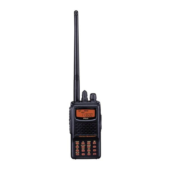
- Page 1 AIR BAND TRANSCEIVER Operating Manual VXA-210...
-
Page 2: Table Of Contents
ONTENTS Important Notice! ............1 Barometric Pressure/Altitude Metering ....22 Introduction ..............2 Thermometer Calibration ..........22 Controls & Connectors ..........3 Correcting the Atmospheric Pressure Meter (Barometer Offset) .. 23 Top Panel ................3 Correcting the Altimeter setting (Altimeter Offset) ..23 Front Panel ................ -
Page 3: Important Notice
50% of the time can cause FCC RF exposure compliance requirements to be exceeded. The radio is transmitting when the red LED on the top of the radio is illuminated. You can cause the radio to transmit by pressing the P-T-T button. ¦ Always use Vertex Standard authorized accessories. VXA-210 P ILOT... -
Page 4: Introduction
You now have at your fingertips a valuable communications tool-a Vertex Standard two-way radio! Rugged, reliable and easy to use, your Vertex Standard radio will keep you in constant touch with your colleagues for years to come, with negligible maintenance down-time. -
Page 5: Controls & Connectors
& C ONTROLS ONNECTORS ANEL Antenna Jack This SMA jack accepts the supplied flexible an- tenna, or another antenna designed to provide 50 W impedance on the Aircraft Communication Band. POWER/VOLUME Knob DIAL Turn this control clockwise to turn the radio on and to increase the volume. -
Page 6: Front Panel
& C ONTROLS ONNECTORS RONT ANEL LCD (Liquid Crystal Display) The display shows the selected operating condi- tions as indicated on the next page. Loudspeaker The internal speaker is located in this position. Microphone Speak across this opening in a normal voice level while pressing the PTT switch, to transmit. -
Page 7: Lcd Display
& C LCD D ONTROLS ONNECTORS ISPLAY This field displays the course This is the Course Deviation Indicator, used heading in degrees. See page 33. during VOR Navigation. See page 32. This icon indicates that This indicator confirms the “Book” Memory Bank that Secondary Key Func- is in use. -
Page 8: Keypad
& C ONTROLS ONNECTORS EYPAD Primary Function Frequency Entry Frequency Entry Frequency Entry Selects Memory Display ( Press Key ) Digit 1 Digit 2 Digit 3 Type (page 27) Secondary Function Selects Selects Activates DVOR mode Locks the Keypad “TO” VOR mode “FROM”... -
Page 9: Left Side
& C ONTROLS ONNECTORS PTT ( P ) Switch Press this button to transmit when you are oper- ating in the COM band. Release this button to return to the “R ” mode. See page 16. ECEIVE MONITOR Switch This button may be pressed to “open” the squelch manually, allowing you to listen for very weak signals. -
Page 10: Right Side
Because these jack connections are unique, using a Speaker/Microphone that is not specified by Vertex Standard may damage the VXA-210. EXT DC Jack When an external 12-Volt DC power source is available, you may connect the (optional) E-DC- 5B External DC Cable here. -
Page 11: Before You Begin
EFORE EGIN Precautions Battery Installation and Removal r This apparatus is capable of two-way communi- ¦ To install the battery, hold the transceiver with cation on channels used for critical aviation safety your left hand, so your palm is over the speaker communications. -
Page 12: Battery Charging
EFORE EGIN Battery Charging low the appropriate instructions provided with the charger/battery. Contact your Dealer if you It is necessary to fully charge the Ni-Cd battery be- have any doubts about the appropriateness of the fore its first use. Follow these procedures: particular charger or battery pack you intend to ¦... -
Page 13: Low Battery Indication
Ni-Cd bat- tery pack. Vertex Standard recommends that you The FBA-25 must not be used with re- carry an extra, fully-charged pack with you so chargeable cells. -
Page 14: Operation
PERATION Preliminary Steps Operation Quick Start ¦ Install a charged battery pack onto the transceiver, r To turn the radio on, as described previously. rotate the VOLUME ¦ Screw the supplied antenna onto the Antenna knob out of the jack. Never operate this transceiver without an click-stop. - Page 15 PERATION r Rotate the VOL- To set 118.275 MHz, you do not need to press the final “5” in the frequency: UME knob to set the [ 1 ] à [ 1 ] à [ 8 ] à [ 2 ] à [ 7 ] . volume level.
-
Page 16: Squelch Adjustment
PERATION r To turn the radio off, Accessing the 121.5 MHz Emergency Frequency turn the VOLUME The VXA-210 can quickly access the 121.500 MHz knob fully counter- Emergency Frequency. This function can be activated clockwise into the even when the keypad lock function is in use. click stop position. -
Page 17: Tuning Methods
PERATION ¦ BOOK (Pre-Programmed) Memories Tuning Methods The Book memories are Throughout this manual, you will see references to pre-programmed, either several different frequency setting methods. Each will at the factory or by your be particularly useful in a particular operating situa- Dealer (depending on tion, and they are described below: your country’s requirements), typically including... -
Page 18: Transmission
PERATION Transmission Reception of Weather Channel Broadcasts To transmit, press and (USA version only) hold the PTT switch. The VXA-210 can receive VHF Weather Channel Speak into the micro- broadcasts, which may assist your flight planning. phone area of the front The VXA-210 includes a ten-channel auto-search panel grille in a normal feature, which simplifies access to Weather Chan-... - Page 19 PERATION r To exit the Weather Pressing the PTT switch re-initiates the scanning Press process. Channel mode, press r I f t h e r e a r e n o the DIAL selector Weather Channels in knob momentarily to your area, the scan- return to the VFO ner will not stop.
-
Page 20: Monitor Key
PERATION Monitor Key ANL (Automatic Noise Limiter) Feature When listening to a very weak signal from an air- For reduction of impulse noise, such as that produced craft or ground station, you may observe the signal by an engine’s ignition system, the ANL feature may disappearing periodically as the incoming signal prove helpful. -
Page 21: Temperature Display
PERATION Temperature Display LOCK Function The VXA-210 can measure the current temperature. The lock function prevents accidental changes to the frequency setting and the keypad controls. r To display the cur- r To activate the lock rent temperature, press [ F ] à [ 6 feature, press [ F ] à... -
Page 22: Receive Battery Saver Setup
PERATION øABS: Automatic Battery Saver, based on activity Receive Battery Saver Setup on the receiver. An important feature of the VXA-210 is its Receive Battery Saver, which “puts the radio to sleep” for a The setting of 1:5 will promote the greatest conser- time interval, periodically “waking it up”... -
Page 23: Beep On/Off
PERATION Beep On/Off The VXA-210’s key/button beeper provides conve- nient audible feedback whenever a button is pressed. Each key and button has a different beep pitch, and each function has a unique beep combination. When you are scanning, the beeper will be heard each time the scanner halts on a busy channel. -
Page 24: Barometric Pressure/Altitude Metering
AROMETRIC RESSURE LTITUDE ETERING Thermometer Calibration The optional Barometric Pressure Unit (SU-1) brings r Press the [ F ] key, then press the DIAL selector to the VXA-210 the unique capability of providing readout of the current barometric pressure. This in- knob to activate the Menu (“SET”) mode. -
Page 25: Correcting The Atmospheric Pressure Meter (Barometer Offset)
AROMETRIC RESSURE LTITUDE ETERING Correcting the Atmospheric Pressure Meter Correcting the Altimeter Setting (Barometer Offset) (Altimeter Offset) r Press the [ F ] key, then press the DIAL selector r Press [ F ] à [ 5 ( ALT.SET )] to enable the Altim- knob to activate the Menu (“SET”) mode. -
Page 26: How To Measure The Rarometric Pressure Or Altitude
AROMETRIC RESSURE LTITUDE ETERING How to Measure the Barometric Pressure Weather Sensor Mode or Altitude The Weather Sensor Mode allows the user to ac- r Press [ F ] à [ 6 tivate only the sensor and display circuits of the ( SENSR )] ;... - Page 27 AROMETRIC RESSURE LTITUDE ETERING - TEMP - - BARO - - ALTI - (Display the current (Display the current (Display the current Temperature) Barometric Pressure) Altitude) ô ô ô Press - D ALT - - GRPH - ø (Display the Density Altitude (Display the relative changes in the Barometric pressuer) ø...
-
Page 28: Memory Operation
EMORY PERATION Memory Storage The VXA-210 provides 50 user-programmable “Main” memories, labeled “CH - 001” through r Select the desired frequency in the VFO mode, “CH - 050,” and up to 100 pre-programmed memo- or recall the Book Memory channel or Weather ries, designated “Book”... -
Page 29: Recalling The Memories
EMORY PERATION Recalling the Memories the desired first character appears, press the DIAL r Press the DIAL selector knob, repeatedly if nec- selector knob momentarily to move on to the next essary, until “MR” (Memory Recall) appears on character. the display. In the MR mode, you will see “CH - ” r Select succeeding characters in the same man- and the previously selected channel number ap- ner, pressing the DIAL selector knob momentarily... -
Page 30: Scanning Operation
CANNING PERATION r While the scanner remains paused on a frequency, The VXA-210 allows you to scan automatically in ø 1 the VFO , Main Memory, “Book” Memory, or the decimal point of the frequency display blinks. ø2 Weather Channel modes. -
Page 31: Channel-Skip Scanning
CANNING PERATION r You can also designate a channel to be skipped Channel-Skip Scanning while scanning. When the receiver is halted on a Continuous-carrier stations like ATIS (Automatic channel that you wish to skip, press and hold the Terminal Information Service) or Weather Broadcast [ SCAN ( DW )] key for 2 seconds (the “t”... -
Page 32: Dual Watch Operation
ATCH PERATION The Dual Watch feature automatically checks for While receiving on the priority channel, if you ø activity on a “priority” channel while you are oper- momentarily press the PTT switch, Dual Watch ating on another channel. During Dual Watch opera- will be disabled. -
Page 33: Priority Dual Watch Operation
RIORITY ATCH PERATION r To start Priority Dual Watch, press [ F ] à [ SCAN Similar to Dual Watch operation (described on pre- ( DW )] . The “DW” icon will appear on the dis- vious page), Priority Dual Watch is an enhanced ver- sion which includes the following additional features: play. -
Page 34: Vor Navigation
VOR N AVIGATION General VOR Equipment COURSE Indicator COURSE Deviation Needle TWO-Degree Deviation Marks “TO”-“FROM” Flag Indicator FROM COM BAND NAV BAND (108.000 - 117.975 MHz) (118.000 - 136.975 MHz) DVOR MODE CDI MODE COURSE Indicator COURSE Deviation Needle ž •... -
Page 35: To Select The Dvor Mode
VOR N AVIGATION the [ )] key momentarily again to return To Select the DVOR Mode r When entering the NAV band (108.000 - 117.975 to the smaller displays. MHz), the VXA-210 selects the DVOR mode au- COURSE Indicator “TO”-“FROM” Flag Indicator tomatically. -
Page 36: Flying To A Vor Station
VOR N AVIGATION Flying to a VOR Station The Aircraft is “ON COURSE” The VXA-210 can indicate the deviation from the direct course to a VOR station. r Select a VOR station on your aeronautical chart and turn the DIAL selector knob (or enter the frequency directly with the keypad) to the fre- OFF COURSE to the “right”... - Page 37 VOR N AVIGATION The Aircraft is “ON COURSE” VOR TAC Magnetic Los Angeles North LAX - 113.600MHz Station The Aircraft is “OFF COURSE” VOR TAC Magnetic Los Angeles North LAX - 113.600MHz Station VXA-210 P ILOT PERATING ANUAL...
-
Page 38: Entering A Desired Course
VOR N AVIGATION Entering a Desired Course Note 2: If the overflow indicator “u” appears on the right side, select a heading plus 10 de- The VXA-210 can also be configured to indicate the grees to the desired course; if the overflow indi- deviation from the desired course, not only the de- cator “t”... -
Page 39: Position Cross-Checking
VOR N AVIGATION r Now set the frequency of the other VOR station Position Cross-checking r Select two VOR stations on your aeronautical in the DVOR mode. Note the radial from the sta- tion you are on. chart. r Extend the radials from each VOR station on the r Set the frequency of one of the VOR stations in chart. -
Page 40: Split Operation
VOR N AVIGATION Split Operation Operating in the Split Mode r It is assumed that you have already set the de- The split operation feature allows you to transmit a sired VOR station’s frequencies (in the NAV call to a Flight Service Station using the COM band band) per the above instructions. -
Page 41: Field Programming Mode
IELD ROGRAMMING r To label a memory with an alpha/numeric name, The VXA-210’s Book Memories also allow the user to store, label, and recall channel frequencies which the next step is to use the DIAL selector knob to you may want to use frequently while the VXA-210 select any of the 48 available characters (includ- is in the Field Programming mode. -
Page 42: Menu ("Set") Mode
“S ” 4. Rotate the DIAL selec- The Menu system allows certain aspects of your radio’s configuration to be customized for your per- tor knob to change the sonal operating convenience. We do not recommend setting of the item (ON that any of the default settings be changed, however, to OFF, etc.). -
Page 43: Menu Listing
“S ” 01 [ SQL ] MENU Listing A listing of the Menu items available via the SET Function: Squelch Level Setting mode may be found below. Available Values: 0 ~ 8 Default Setting: 2 Menu Menu Available Function Default Select a setting for this Menu item which just si- Item Values... - Page 44 “S ” 03 [ RESM ] 05 [ BEEP ] Function: Scan-Resume Mode Setting Function: Keypad Beeper On/Off Available Values: CAR/5 Available Values: on/oFF Default Setting: CAR Default Setting: on In the “CAR” (Carrier Drop) mode, the scanner will If you do a lot of scanning, you may wish to set this remain halted for as long as there is a carrier present Menu item to “oFF,”...
- Page 45 “S ” 07 [ LAMP ] 10 [ DWMD ] Function: Display and Keypad Illumination Mode Function: Select the Dual Watch/Priority Function Available Values: KEY/TGL/5 Available Values: DW/PRI Default Setting: KEY Default Setting: DW In the “KEY” mode, the lamp will be activated for 5 In the DW mode, the VXA-210 will activate the Dual Watch feature when you press [ F ] à...
- Page 46 “S ” 13 [ EMRG ] 14 [ TEMP ] Function: Emergency channel On/Off Function: Correcting the Thermometer setting Available Values: on/oFF Available Values: –12.7 ~ +12.7 °C Default Setting: on Default Setting: 0 °C This controls the operation of the Emergency [ 121.5 ] This allows you to calibrate the internal thermom- key.
-
Page 47: Installation Of The Su-1
Barometer or Altimeter devices ceiver. We recommend that this Rubber Cushion used for navigation critical to personal safety. be put on the bottom of the SU-1. VERTEX STANDARD CO., LTD. MADE IN JAPAN VERTEX STANDARD CO., LTD. MADE IN JAPAN VERTEX STANDARD CO., LTD. -
Page 48: Accessories & Options
“U” suffix is for use with 230 VAC. Availability of accessories may vary. Some accessories are supplied as standard per local requirements, while others may be unavailable in some regions. Consult your Vertex Standard Dealer for details regarding these and any newly-available options. - Page 49 & O CCESSORIES PTIONS á External Antenna Headset (not supplied) CN-3 Antenna Adapter (Option) CT-60 Headset Cable PTT Switch (not supplied) An external PTT switch is required for use with an E-DC-5B External Power Cable (Option) aviation headset VXA-210 P ILOT PERATING ANUAL...
-
Page 50: Specifications
PECIFICATIONS General Frequency Range: TX: 118.000 - 136.975 MHz, RX: 108.000 - 136.975 MHz, Weather Channels (WX-01 - WX-10: USA version only) Channel Spacing: 25 kHz Emission Type: TX: AM, RX: AM & FM (FM: for receiving the Weather Channels, USA version only) Supply Voltage: 6.0 - 15.0 VDC Current Consumption (approx.): 10 µA (power off), 30 mA (battery saver on, saver ratio 1:5) - Page 51 If the dealer is unable to assist you, you may contact This time will vary, based on our current us at Vertex Standard USA. We can be reached by workload. telephone at (562) 404-2700 (ask the operator for r We can provide repair estimates upon your re- Avionics Product Support).
- Page 52 VERTEX STANDARD CO., LTD. Copyright 2001 4-8-8 Nakameguro, Meguro-Ku, Tokyo 153-8644, Japan VERTEX STANDARD CO., LTD. VERTEX STANDARD US Headquarters All rights reserved. 17210 Edwards Rd., Cerritos, CA 90703, U.S.A. International Division No portion of this manual may be 8350 N.W. 52nd Terrace, Suite 201, Miami, FL 33166, U.S.A.