Table of Contents
Advertisement
set uP anD OPerating instructiOns
Visit our website at: http://www.harborfreight.com
read this material before using this product.
Failure to do so can result in serious injury.
saVe this Manual.
©
Copyright
2010 by Harbor Freight Tools
contained herein may be reproduced in any shape or form without the express written consent of
Harbor Freight Tools. Diagrams within this manual may not be drawn proportionally. Due to continuing
improvements, actual product may differ slightly from the product described herein. Tools required for
assembly and service may not be included.
For technical questions or replacement parts, please call 1-800-444-3353.
Manual revised 10f
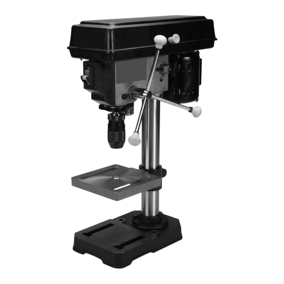
8" Drill Press
Model
®
. All rights reserved. No portion of this manual or any artwork
44505
Advertisement
Table of Contents

Related Manuals for Central Machinery CENTRAL MACHINERY 44505


Summary of Contents for Central Machinery CENTRAL MACHINERY 44505
- Page 1 Harbor Freight Tools. Diagrams within this manual may not be drawn proportionally. Due to continuing improvements, actual product may differ slightly from the product described herein. Tools required for assembly and service may not be included.
-
Page 2: Table Of Contents
...3 general tOOl saFetY Warnings . 3 grOunDing instructiOns ...5 110-120 V~ grOunDeD tOOls: tOOls With three PrOng Plugs 5 Drill Press saFetY Warnings ... 5 sPeciFicatiOns ...8 unPacking ...8 instructiOns FOr Putting intO use ...8 asseMblY/MOunting ... 8 OPerating instructiOns ...10... -
Page 3: Important Safety Information
saVe this Manual Keep this manual for the safety warnings and precautions, assembly, operating, inspection, maintenance and cleaning procedures. Write the product’s serial number in the back of the manual near the assembly diagram (or month and year of purchase if product has no number). - Page 4 USE RIGHT TOOL. Don’t force tool or attachment to do a job for which it was not designed. recOMMenDeD MiniMuM Wire gauge FOr eXtensiOn cOrDs (120 VOlt) eXtensiOn cOrD naMePlate aMPeres (at full load) 25’ 50’ 0 – 6 6.1 – 10 10.1 –...
-
Page 5: Grounding Instructions
Do not use an adapter to connect this tool to a different outlet. Drill Press safety Warnings For Your Own safety read instruction Manual before Operating Drill Press Wear eye protection. Do not wear gloves, necktie, or loose clothing. Clamp workpiece or brace against column to prevent rotation. - Page 6 Maintain labels and nameplates on the tool. These carry important safety information. If unreadable or missing, contact Harbor Freight Tools for a replacement. Avoid unintentional starting. Prepare to begin work before turning on the tool. People with pacemakers should consult their physician(s) before use.
- Page 7 diabetes, or Raynaud’s Disease should not use this tool. If you feel any medical or physical symptoms related to vibration (such as tingling, numbness, and white or blue fingers), seek medical advice as soon as possible. Do not smoke during use. Nicotine reduces the blood supply to the hands and fingers, increasing the risk of vibration-related injury.
-
Page 8: Specifications
Assembly hardware is located in separate bags/boxes. Each contains the necessary parts for each assembly step. Remove all packing and protective material from the Drill Press components. instructiOns FOr Putting intO use read the entire iMPOrtant saFetY inFOrMatiOn section at the beginning of this... -
Page 9: Operating Instructions
11. Verify that the Table (C7) is square (90 degrees) to the Head Assembly and drill bit. Secure a three inch drill bit in the Chuck (hand tighten, no chuck key is required). Raise the Table to within four inches of the Chuck. -
Page 10: Tool Set Up
Loosen the Hex Nuts (31) and screw both toward the top of Stop Rod (B12). Turn the Feed Wheel counterclockwise to bring the tip of the drill bit down, next to the hole depth mark. Page 10 For technical questions, please call 1-800-444-3353. - Page 11 Push the Switch up to turn the Motor ON. Pull down on the Feed Knob and slowly drill the hole into the workpiece. Warning: If the drill bit grabs and spins the workpiece, do not attempt to stop the spinning with your hands. Step back, and push the Switch down to the OFF position.
-
Page 12: Maintenance And Servicing
Maintenance anD serVicing Procedures not specifically explained in this manual must be performed only by a qualified technician. tO PreVent seriOus injurY FrOM acciDental OPeratiOn: turn the Power switch of the tool to its “OFF” position and unplug the tool from its electrical outlet before performing any inspection, maintenance, or cleaning procedures. - Page 13 adjusting the Feed Wheel return tension spring cautiOn! Wear an ansi-approved full face shield during this procedure. Move the Chuck to its uppermost position. Loosen Hex Nuts (31) and move both to the lowermost position. This will keep the Chuck from falling during this adjustment.
-
Page 14: Troubleshooting
Dull drill bit Drilling too slowly Lacking lubrication Drill bit wobbles Bent bit Worn Spindle Bearings Drill bit not in Chuck correctly Chuck not properly installed Feed Wheel returns Tension Spring not in adjustment slowly, or too fast Drill bit binds... -
Page 15: Parts Lists And Diagrams
Please reaD the FOllOWing careFullY THE MANUFACTURER AND/OR DISTRIBUTOR HAS PROVIDED THE PARTS LIST AND ASSEMBLY DIAGRAM IN THIS MANUAL AS A REFERENCE TOOL ONLY. NEITHER THE MANUFACTURER OR DISTRIBUTOR MAKES ANY REPRESENTATION OR WARRANTY OF ANY KIND TO THE BUYER THAT HE OR SHE IS QUALIFIED TO MAKE ANY REPAIRS TO THE PRODUCT, OR THAT HE OR SHE IS QUALIFIED TO REPLACE ANY PARTS OF THE PRODUCT. -
Page 16: Head Assembly Diagram
head assembly Diagram Page 16 For technical questions, please call 1-800-444-3353. SKU 44505... -
Page 17: Parts List And Diagram A - Pulley And Spindle
Parts list and Diagram a - Pulley and spindle Part A10 Insert, Pulley A11 Pulley, Spindle A12 Nut, Pulley A13 Clamp, Cord A14 Screw, Pan Hd., M5x0.8-16 A15 Washer, Foam When ordering a part from this drawing, add an “A” prefix to the part number. SKU 44505 For technical questions, please call 1-800-444-3353. -
Page 18: Parts List And Diagram B - Chuck And Spindle Shaft
Parts list and Diagram b - chuck and spindle shaft Page 18 For technical questions, please call 1-800-444-3353. Part Description Gasket, Quill Bearing, Ball, 12 mm Tube, Quill Screw, Pan, M5x0.8-20 Collar, Stop Ring, Retaining Shaft, Spindle Chuck B10 Nut, Hex, M6x1.0 B11 Nut, Hex, M5x0.8 B12 Stop, Rod When ordering a part from this drawing,... -
Page 19: Parts List And Diagram C - Base And Table
Parts list and Diagram c - base and table When ordering a part from this drawing, add a “C” prefix to the part number. SKU 44505 For technical questions, please call 1-800-444-3353. Part Description Support, Table with Scale Support, Lock Handle Tube, Support Base Screw, Hex Hd., M8x1.25-20... -
Page 20: Limited 90 Day Warranty
90 DaY WarrantY Harbor Freight Tools Co. makes every effort to assure that its products meet high quality and durability standards, and warrants to the original purchaser that this product is free from defects in materials and workmanship for the period of 90 days from the date of purchase.