Advertisement
Advertisement
Table of Contents

Summary of Contents for Maytag MLG2000AXW
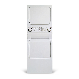
- Page 1 STACKED WASHER/DRYER INSTALLATION INSTRUCTIONS FACTORY STACKED VERSION The installation, including a proper exhaust system, is the responsibility of the owner. LEAVE THESE INSTRUCTIONS WITH THE OWNER For further information, call 1-888-4-MAYTAG (1-888-462-9824). 6 2721750 Printed in U.S.A.
-
Page 2: Items Provided
Read this before you start... TOOLS needed for installation • Teflon tape or pipe joint • Screw driver (standard) compound (gas) • Duct tape • Cutting knife • Crescent wrench • Pipe wrench (gas) • 3/8" nut driver • 5/16" nut driver (electric - U.S. - Page 3 PLEASE READ THE FOLLOWING INSTRUCTIONS CAREFULLY BEFORE STARTING TO INSTALL DRYER. THESE INSTRUCTIONS SHOULD BE RETAINED FOR FUTURE REFERENCE. FOR GAS DRYERS THE INSTALLATION MUST CONFORM WITH THE NATIONAL FUEL GAS CODE ANSI Z223.1, LATEST REVISION. ANY QUESTIONS CONCERNING THIS SHOULD BE REFERRED THE LOCAL GAS UTILITY.
- Page 4 Exhaust Hood Type Number 90 ° Turns Maximum length of 4-inch diameter rigid metal duct 65 ft. 59ft. 54 ft. 48 ft. 44 ft. 38 ft. 36 ft. 30 ft. 28 ft. 22 ft. Maximum length of 4-inch diameter flexible stiff walled metal duct 36 ft.
-
Page 5: Drain Facility
WASHER REQUIREMENTS Water pressure of 20 to 120 p.s.i, is required to correctly fill the washer to the proper levels. DRAIN FACILITY Recommended height of the stand pipe is 36 inches. If the stand pipe is less than 36 inches high, the drain hose should be routed through the clip to raise the hose to the proper... -
Page 6: Gas Requirements
GAS REQUIREMENTS Use only Natural or LP (liquid propane) gases. THE INSTALLATION MUST CONFORM WITH LOCAL CODES, OR IN THE ABSENCE OF LOCAL CODES, WITH THE NATIONAL FUEL GAS CODE ANSI/Z223.1, LATEST REVISION (FOR THE UNITED STATES), OR WITH THE CAN/CGA-B149 INSTALLATION CODES (FOR CANADA). -
Page 7: Electrical Requirements
ELECTRICAL REQUIREMENTS _WARNING WARNING - To prevent unnecessary risk of fire, NOTE: Wiring diagram is located inside the access panel. electrical shock personal injury, all wiring Export models (not U.S. or Canada): and grounding must done in accordance See Additional Instructions for Export Models on the following with local codes,... -
Page 8: Electric Models
Canada to 208 Additional Instructions for Export Models (not U.S. or Canada) Contact the distributor that sold the appliance or: Maytag International, 8700 W. Bryn Mawr Avenue, Chicago, Illinois USA 60631,773-714-0100, for information on product,... - Page 9 ADDITIONAL INFORMATION REPLACEMENT PARTS ACCESSORIES If the dryer requires replacement parts or accessories, contact your local Maytag dealer from whom you purchased your appliance Maytag Customer Service 240 Edwards Street, S.E. Cleveland, Tennessee 37311 Phone 1-888-4-MAYTAG (1-888-462-9824), for information on the nearest authorized...
-
Page 10: Units Only
To install... Carefully remove any packaging materials from the outside of the appliance. • aside two corner posts for installation. IMPORTANT: Notice that the hoses are tied up with a shipping strap. (See figure 1.) The strap should not be cut or removed until the machine is ready... - Page 11 HOSE RETAINER Remove hose from the drain hose clip. Place the drain hose in the drain facility. To change drain hose direction or prevent hose from collapsing or becoming damaged, turn the end of the hose while holding the base of the hose stationary. (See figure 8.) To prevent accidental...
- Page 12 For gas dryers apply joint compound or about 1-1/2 wraps of Teflon tape over threaded connection on the end of the gas pipe. (See figure 11.) An elbow is recommended, for additional depth, pointing down to allow the unit to be located further back into the alcove.
- Page 13 For electric dryers: TO MAKE ELECTRICAL CONNECTION FOR U.S. DRYERS Review electrical requirements on page 6 of these instructions. IMPORTANT - All U.S. models are produced for a 3-WIRE SYSTEM CONNECTION. The dryer frame is grounded to the Terminal Block neutral conductor at the terminal...
- Page 14 2-WIRE AND GROUND SYSTEM 2-Wire and Ground S' 'stem CONNECTIONS Remove the terminal block cover plate. Insert the power cord with an agency listed strain relief through the hole provided in the cabinet near the terminal block. Note, a strain relief must be Neutral used.
- Page 15 Directions for reversing the dryer door: 1. Remove the hinge hole covers and screws. 2. While supporting the door, remove 4 screws in the hinges that secure the hinges to the cabinet set the door down. 3. Move the following parts to the opposite side of the door: 2 hinges...
-
Page 16: Final Installation
FINAL INSTALLATION CHECK LIST Instruction and Installation Kits have been removed. Shipping straps have been removed. Appliance is level with all legs firmly on the floor, with the lock nuts tightened against the base. Drain hose is properly located into drain facility, snapped into drain hose retainer and is not kinked. -
Page 17: Installation
INSTALLATION ACCESSORIES • Vent hood - 4" (10.16cm) opening - 059129 • Aluminum pipe - 4" x 24" (10.16cm x 60.96cm) - 059130 • Aluminum elbow - 4" (10.16cm) - 059131 • Aluminum window plate - 15" x 20" (38.10cm x 50.80cm) - 4"...


