Table of Contents
Advertisement
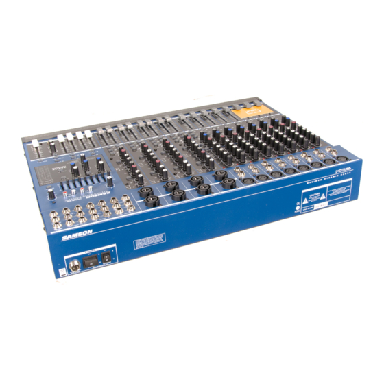
MDR16
�������� �
�������� �
�������� �
�������� �
�������� �
�������� �
�������� �
����
����
����
����
����
����
������
������
������
������
������
������
��
��
��
��
��
��
��
����
����
����
����
����
����
����
����
����
����
����
����
�
��
�
��
�
��
�
��
�
��
�
��
�
���
�
���
���
�
���
���
�
���
���
�
���
���
�
���
���
�
���
���
�
��
��
��
��
��
��
�
�
�
�
�
�
�
�
�
�
�
�
�
���
���
���
���
���
���
����
����
����
����
����
����
����
���
���
���
���
���
���
���
���
���
���
���
���
���
���
�
�
�
�
�
�
�
��
��
��
��
��
��
��
��
��
��
��
��
��
� �
� �
� �
� �
� �
� �
� �
� �
� �
�
� �
�
�
� �
�
�
� �
�
�
� �
�
�
� �
�
�
�
�
� �
� �
� �
� �
� �
� �
� �
� �
� �
� �
� �
� �
� �
� �
������� �
������� �
������� �
������� �
������� �
������� �
������� �
SIXTEEN CHANNEL MIXER
WITH 24BIT DIGITAL EFFECTS
WITH 24BIT DIGITAL EFFECTS
WITH 24BIT DIGITAL EFFECTS
WITH 24BIT DIGITAL EFFECTS
�������� �
�������� �
�������� ��
�������� ��
�������� ��
����
�������� ��
�������� ��
�������� ��
�������� ��
������
��
�
�
�
�
��
��
��
��
����
����
�
�
�
�
�
�
�
�
���
���
���
���
�
��
��
��
��
��
��
��
��
��
��
��
����
����
��
�
��
��
��
��
��
��
��
��
��
���
���
�
���
�
�
�
�
��
��
��
��
��
��
�
�
�
�
�
����
�
�
����
�
�
����
�
�
����
���
���
��
��
��� ���
��
��
��� ���
�
���
���
�
��
���
���
����
�����
�
��
��
�
�
���
���
��
��
��
��
��
��
��
�
��
��
��
����
�
�
����
�
����
��
��
��
��� ���
��
��
��� ���
��
��� ���
�
���
���
���
�
��
��
���
���
���
����
�����
�����
����
����
����
����
����
���
���
���
���
���
���
���
���
���
���
�
����
�����
�����
�����
��
��
��
��
��
��
��
��
��
��
��
��
��
��
� �
� �
� �
� �
� �
� �
� �
� �
� �
�
�
� �
�
�
� �
�
� �
�
�
� �
�
� �
�
�
� �
�
� �
�
�
� �
�
� �
� �
� �
� �
� �
� �
� �
� �
� �
� �
� �
� �
� �
� �
� �
� �
� �
� �
� �
������� �
������� ����
������� �����
������� �����
������� �����
CHANNEL MIXER
CHANNEL MIXER
CHANNEL MIXER
�
������
�
�
������
�
�
��� ������
�
��� ����
�
�������
�
�
��� ���
�
�
��
�
��� �����
�
�������
�
�
��� ����
�
�
��� ����
�
���� ���
�� �� ���
�
�
�� ��
�� ���
�
��
���� �����
�� ������
�����
��
�
�
�
�
�� �� ��� �
�
�
�
��
�����
�����
���
��
�
��
�
�
��
�
���
��� ���
����
�
�
�
� ����� ����
� ������ ����
� ����� ����
� ������������
� ����� ����
� ���������
���
������� �������
����
����
��������
��� �� ���
��� �� ���
�����������
��������
�
�������
�
�
�������
�
������
�
���
�
��
��
��
��
��
����
� �
� �
� �
� �
�����
� �
�
�
� �
�
� �
� �
�
� �
�
� �
�
� �
� �
� �
� �
� �
� �
� �
� �
� �
� �
�
�������
�
�
�������
�
������
�
���
�
Advertisement
Table of Contents

Related Manuals for Samson MDR16


Summary of Contents for Samson MDR16
- Page 1 MDR16 �������� � �������� � �������� � �������� � �������� � �������� � �������� � �������� � �������� � �������� �� �������� �� �������� �� � ������ � � ������ � � ��� ������ � ��� ���� � ������� �...
- Page 2 Safety Instructions/Consignes de sécurité/Sicherheitsvorkehrungen/Instrucciones de seguridad WARNING: To reduce the risk of fire or electric shock, do not expose this unit to rain ATTENTION: Pour éviter tout risque d’électrocution ou d’incendie, ne pas exposer or moisture. To reduce the hazard of electrical shock, do not remove cover or back. cet appareil à...
-
Page 3: Table Of Contents
Introduction MDR16 Features Front Panel Layout Rear Panel Layout Controls and Functions Mono Input Channel Section 7–11 Master Section 11–15 MDR16 Input and Output Connections 16–17 Operating the MDR16 18–21 System Set-ups 22–23 MDR16 Wiring Guide Specifications Block Diagram Notes 27-28 Copyright 2004, Samson Technologies Corp. -
Page 4: Introduction
DSP effect to BUS 1 & 2, BUS 3 & 4 and even to AUX 1 to add effects to your monitor mix. The MDR16 features a nine- band stereo graphic equalizer allowing you to contour the frequency response of your speaker system for that sound that's sweet to you. -
Page 5: Mdr16 Features
� ��� � The Samson MDR16, sixteen channel mixer with onboard 24 BIT DSP is a comprehensive, all-in-one solution for live sound, recording, fixed installation and post production applications. Here are some of its main features: • Sixteen channels – Eight Mic/Line plus four Stereo/Dual inputs with mic pre’s for a total of 16 microphone inputs. -
Page 6: Front Panel Layout
Front Panel Layout ���... -
Page 7: Front Panel Layout
Front Panel Layout CLIP – Red LED will illuminate, indicating when the GAIN 1 or AUX 2 bus by using the AUX1/2 switch which lights , EQ, or channel fader control has been adjusted too when set to AUX2. high. LOW FREQUENCY (Stereo Channels) - Controls the GAIN –... -
Page 8: Rear Panel Layout
Phantom Power is on. This control knob is used to adjust the DSP 3/4 – POWER LED – Indicates the MDR16 is powered up. level of the internal DSP effect in the Bus 3/4 out- SOLO LED – Indicates SOLO is selected. -
Page 9: Controls And Functions
15dB. LOW CUT FILTER Each of the MDR16’s channels include a LOW CUT (or high pass) filter which rolls off the low frequencies from 80Hz and below at the rate of 18dB per octave. - Page 10 LEVEL control. The MDR16’s PAN control is used to place or position the mono signal into the stereo main Left and Right MIX bus. You can create a stereo image by panning some input signals to the left and others to the right. The MDR16’s PAN control is a Power-Pan circuit, which includes a 3dB dip in the center position.
- Page 11 ������� � switch can be found later in this manual. FADER The MDR16’s 60mm input FADER controls the overall channel level. The input FADER features an audio taper and no detents for smooth fades. STEREO - DUAL/MONO INPUT CHANNEL SECTION The MDR16’s input channels nine through sixteen are STEREO or DUAL...
- Page 12 (STEREO/DUAL-MONO INPUT CHANNEL CONTINUED) CHANNEL EQUALIZER The MDR16 Stereo/Dual-mono input channels feature a 2-band equalizer allowing you to adjust the high and low fre- quencies independently on each channel. The channel’s frequency response is flat when the knobs are in the "12:00"...
-
Page 13: Master Section
Graphic Equalizer The MDR16’s 9-band Graphic Equalizer allows you to contour the frequency response of the Left and Right MIX, or the AUX1 mix for using monitors, providing a maximum of 12dB of cut/boost for each frequency band. This is an especially useful tool for cutting frequencies that cause annoying feedback. -
Page 14: Bit Digital Effect Section
Medium Hall, 3-Large Room, 4-Vocal Room 1, 5-Vocal Room 2, 6-Chorus + Reverb, 7-Chorus + Delay, 8-Stairwell DSP ON The MDR16’s internal effects processor is engaged by using the DSP ON switch. When you press the DSP ON switch in, the green LED will light indicating that the digital effects are on. - Page 15 Auxiliary Returns The MDR16 has two stereo auxiliary returns, which can be accessed via the two pairs of 1/4-inch phone jacks located on the top panel. The auxiliary returns can be used to connect any stereo line level signal, but they are primarily used to con- nect the output of external effects processors.
- Page 16 Controls and Functions MASTER OUTPUT SECTION - continued SOLO Switch (1/4 Bus Output) You can listen to the signal from the channels assigned to 1/4 Bus Output in the SOLO bus by pressing the SOLO Switch located above the 1/4 Bus Output Faders. When engaged, the yellow LED illuminates indicat- ing the channel is assigned to the SOLO bus.
-
Page 17: Led Indicators
Controls and Functions MASTER OUTPUT SECTION MIX/2TK The MIX/2TK switch selects the signal source that you are monitoring in the CONTROL ROOM and HEADPHONE outputs. When the switch is in the up position, the signal source is from the LEFT/ RIGHT MIX bus. When the MIX/ 2TK switch is in the down position, the signal source is from the 2 TRACK input. -
Page 18: Mdr16 Input And Output Connections
CHANNEL 1–8 MIC and LINE INPUTS The MDR16’s input channels 1 - 8 each have an XLR MIC level, Low-Z (Low Impedance) input and a 1/4-inch LINE level, Hi-Z (High Impedance) input. By using the GAIN control on channels 1- 8, you can connect a variety of signal sources from microphones and direct boxes to line level devices such as synthesizers and drum machines. - Page 19 EXTERNAL OUTPUT JACKS The MDR16 features several output connectors allowing you to interface a variety of external devices. A stereo recording device such as a cassette recorder can be connected to the 2 Track jacks, and power amplifiers can be connected to the CONTROL ROOM and MAIN output jacks.
-
Page 20: Operating The Mdr16
Turn on your power amp or powered monitors and raise the level control to the manufacturers' recommended oper- ating level. Set the Left and Right MIX faders in the MDR16’s master section to the "0" position. While speaking into the mic (or playing the instrument), adjust the channel Fader control so that the "0" LED of the MAIN section peak level meter lights occasionally. - Page 21 LEFT and RIGHT MIX. 2. In order to get the most gain from your monitor mix, use an external graphic equalizer (like a Samson S curve 131) to cut out any frequencies that cause feedback.
- Page 22 Connect the TRS (TIP / RING / SLEEVE) plug to the channel INSERT point, and then connect the 1/4-inch (TIP / SLEEVE), INSERT SEND plug to the input of the external processor. The signal is sent back to the MDR16, using the 1/4-inch (TIP / SLEEVE), INSERT RETURN plug connecting to the output of the external processor.
-
Page 23: Operating The Mdr16
CD, Tape or Mini Disk. Below is a description of how you � ������ � � ������ � � ��� ������ � ��� ���� can play back a CD, Tape or MD using the MDR16’s 2 TRACK INPUT. � ������� � � ��� ��� � � �� � ��� �����... -
Page 24: System Set-Ups
MDR16 System Set-Ups MDR16 LIVE SOUND SET-UP... -
Page 25: System Set-Ups
MDR16 System Set-Ups MDR16 RECORDING SET-UP ��� ������ ���� ������ ���� ������ ���� ������ ���� ������ ����... -
Page 26: Mdr16 Wiring Guide
MDR16 Wiring Guide CONNECTING THE MDR16 The are several ways to interface the MDR16 to support a variety of applications. The MDR16 features balanced inputs and outputs, so connecting balanced and unbalanced signals is possible. Unbalanced 1/4” Connector Balanced TRS 1/4” Connector... -
Page 27: Specifications
MDR16 Specifications Normal Limit Frequency Response (Trim @ Min, unity gain ± 3 dB) Mic to Main 15 Hz - 54 kHz 20 Hz - 35 kHz Line to Main 5 Hz - 70 kHz Aux Return to Main 5 Hz - 98 kHz... -
Page 28: Block Diagram
MDR16 Block Diagram... -
Page 29: Notes
Notes... - Page 30 Notes...
- Page 32 Samson Technologies Corp. 575 Underhill Blvd. P.O. Box 9031 Syosset, NY 11791-9031 Phone: 1-800-3-SAMSON (1-800-372-6766) Fax: 516-364-3888 www.samsontech.com...