Advertisement
Table of Contents
- 1 Table of Contents
- 2 Introduction
- 3 MDR624 Features
- 4 Controls and Functions
- 5 Front and Rear Panel Layout
- 6 Mono Input Channel Section
- 7 Master Section
- 8 MDR624 Input and Output Connections
- 9 Operating the MDR624
- 10 System Set-Ups
- 11 MDR624 Wiring Guide
- 12 Specifications
- 13 Block Diagram
- 14 Notes
- Download this manual
AUX RET
AUX SEND
MIC IN
MIC IN
LEFT/MONO
RIGHT
PHONES
LINE IN
LINE IN
3/L
5/L
30
30
GAIN
GAIN
LINE IN
LINE IN
6/R
4/R
5
60
5
60
-26
+26
-26
+26
0
0
0
HF
HF
HF
5
5
5
5
5
5
5
12K
12K
12K
10
10
10
10
10
10
10
15
15
15
15
15
15
15
0
0
0
MF
MF
MF
5
5
5
5
5
5
5
2.5K
2.5K
2.5K
10
10
10
10
10
10
10
15
15
15
15
15
15
15
0
0
0
0
0
0
LF
LF
LF
5
5
5
5
5
5
5
80Hz
80Hz
80Hz
10
10
10
10
10
10
10
15
15
15
15
15
15
15
AUX
AUX
AUX
0
10
0
10
0
10
0
0
0
0
0
0
0
PAN
PAN
BAL
L
R
L
R
L
R
L
5
5
5
PEAK
PEAK
PEAK
0
10
0
10
0
10
0
LEVEL
LEVEL
LEVEL
CHANNEL 1
CHANNEL 2
CHANNEL 3/4
CHANNEL 5/6
SIX CHANNEL MIXER
L
CR OUTPUT
R
L
MIX OUTPUT
R
0
2T IN
2T OUT
HF
5
12K
10
LEFT
LEFT
15
0
MF
5
RIGHT
RIGHT
2.5K
10
15
AUX RETURN
0
0
5
LF
5
80Hz
PHANTOM
POWER
10
15
0
10
CLIP
+12
AUX
2TK TO MIX
+6
0
-6
10
-12
2TK TO C/R
-18
0
0
BAL
-24
L
R
OUTPUT LEVEL
R
5
5
5
PEAK
10
0
10
0
10
LEVEL
LEVEL
LEVEL
CR / PHONES
MAIN LEVEL
Advertisement
Table of Contents

Related Manuals for Samson MDR624


Summary of Contents for Samson MDR624
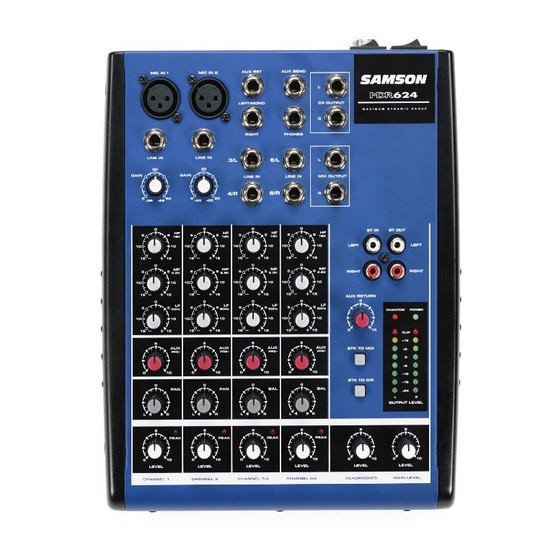
- Page 1 AUX RET AUX SEND MIC IN MIC IN LEFT/MONO CR OUTPUT RIGHT PHONES LINE IN LINE IN GAIN GAIN LINE IN LINE IN MIX OUTPUT 2T IN LEFT RIGHT 2.5K 2.5K 2.5K 2.5K AUX RETURN 80Hz 80Hz 80Hz 80Hz 2TK TO MIX 2TK TO C/R PEAK PEAK...
- Page 2 Safety Instructions/Consignes de sécurité/Sicherheitsvorkehrungen/Instrucciones de seguridad WARNING: To reduce the risk of fire or electric shock, do not expose this unit to rain or moisture. To reduce the hazard of electrical shock, do not remove cover or back. No user serviceable parts inside. Please refer all servicing to qualified per- sonnel.The lightning flash with an arrowhead symbol within an equilateral triangle, is intended to alert the user to the presence of uninsulated "dangerous voltage"...
-
Page 3: Table Of Contents
Introduction MDR624 Features Controls and Functions Front and Rear Panel Layout Mono Input Channel Section Master Section MDR624 Input and Output Connections Operating the MDR624 System Set-ups MDR624 Wiring Guide Specifications Block Diagram Notes Copyright 2004, Samson Technologies Corp. Printed January, 2004 Samson Technologies Corp. -
Page 4: Introduction
Connecting external effects like a reverb or digital delay to the MDR624 is easy thanks to the Aux send on each channel along with the stereo Aux Return in the master section. LED indicators for Power, Phantom, Peak and Main Output Level make it easy to keep your lev- els set correctly and minimize distortion. -
Page 5: Mdr624 Features
The Samson MDR624 six channel mixer, is a comprehensive, all-in-one solution for live sound, recording, fixed installation and post production applications. Here are some of its main features: • Six channels – Two Mic/Line plus two Stereo inputs. • Flexible design topology ideal for live sound, recording and post production. -
Page 6: Controls And Functions
LEVEL LEVEL LEVEL CHANNEL 2 CHANNEL 3/4 CHANNEL 5/6 PHANTOM DESIGNED AND ENGINEERED IN THE UNITED STATES BY SAMSON TECHNOLOGIES CAUTION RISK OF ELECTRICAL SHOCK DO NOT OPEN RISQUE DE SHOCK ELECTRIQUE NE PAS OUVRIR SERIAL NUMBER : AC ADAPTOR... -
Page 7: Front And Rear Panel Layout
21 PHANTOM – Indicates that the 48 Volt Phantom Power is on. 22 POWER – Indicates the MDR624 is powered up. 23 OUTPUT METER - Eight segment display with VU ballistics indicates main Mix level. 24 2 TRACK TO MIX - Switch used to mix the 2 track input with the mix from the channel inputs. -
Page 8: Mono Input Channel Section
The following section details each part of the MDR624’s input channels including the GAIN control, 3-BAND EQ, AUX send, PAN, BALANCE and LEVEL controls. The input channels One and Two on the MDR624 feature high quality, discrete transistor pre-amps providing transparency and extended dynamic range on standard XLR con- nectors. - Page 9 BALANCE (Stereo Inputs Only) The MDR624’s BALANCE control is used to place or position a mono input into the stereo main Left and Right MIX bus. For a stereo input, the balance control is used to center the sound between the Left and Right Mix bus.
-
Page 10: Master Section
Controls and Functions MASTER SECTION The MDR624’s Master section includes the master level controls for the MAIN mix, AUX and CR (Control Room) / PHONES output, as well as, 2-track assign switches and LED metering for power and level. The following section details the function controls and switches in the Master section. - Page 11 0 indicator LED lights occa- sionally. Auxiliary Return The MDR624 has a stereo auxiliary return, which can be accessed via the pair of 1/4-inch phone jacks located on the top panel. The Auxiliary Return can be used to connect any...
-
Page 12: Mdr624 Input And Output Connections
CHANNEL 1 – 6 MIC and LINE INPUTS The MDR624’s channels 1 and 2 mono input channels each have a 1/4-inch connector for line level inputs and XLR connectors for the MIC inputs. Channels 3/4 and 5/6 stereo input channels each have 1/4-inch connectors for line level inputs. - Page 13 2TR OUTPUT If you want to record the mix from your MDR624, you can use the 2-track OUT connectors. The dual RCA connectors can be connected to a CD, Cassette, Mini Disk, DAT or recorder, even the input of a computer sound card for hard disk recording.
-
Page 14: Operating The Mdr624
4. Turn on your power amp or powered monitors and raise the level control to the manufacturers’ recommend- ed operating level. 5. Set the Main Level fader in the MDR624’s master section to the "2 o’clock" position. 6. While speaking into the mic (or playing the instrument), adjust the channel Level control so that the "0" LED of the MAIN section peak level meter lights occasionally. - Page 15 LEFT and RIGHT MIX. 2. In order to get the most gain from your monitor mix, use an external graphic equalizer (like a Samson S curve 131 or E31i) to cut out any frequencies that cause feedback. For more information, see the diagram on pg. 14.
-
Page 16: System Set-Ups
MDR624 System Set-Ups MDR624 LIVE SOUND SET-UP... - Page 17 MDR624 System Set-Ups MDR624 RECORDING SET UP...
-
Page 18: Mdr624 Wiring Guide
MDR624 Wiring Guide CONNECTING THE MDR624 The are several ways to interface the MDR624 to support a variety of applications. The MDR624 features bal- anced inputs and outputs, so connecting balanced and unbalanced signals is possible. Unbalanced 1/4” Connector Balanced TRS 1/4” Connector... -
Page 19: Specifications
Power supply Main Voltage Europe U.K./Australia Power Consumption Physical Dimension Net weight MDR624 Specifications electronically balanced, discrete input configuration 10Hz to 45kHz, +0/- 3dB 0.05% at +4dBu, 1kHz 5dB to 60dB(MIC) 110dB electronically balanced 10Hz to 45kHz, +0/ -3dB 0.05% at +4dBu, 1kHz... -
Page 20: Block Diagram
Block Diagram... -
Page 21: Notes
Notes... - Page 22 Notes...
- Page 24 Samson Technologies Corp. 575 Underhill Blvd. P.O. Box 9031 Syosset, NY 11791-9031 Phone: 1-800-3-SAMSON (1-800-372-6766) Fax: 516-364-3888 www.samsontech.com...