Table of Contents
Advertisement
Quick Links
- 1 Mdr1248 and Mdr1688 Features
- 2 Front Panel Layout
- 3 Controls and Functions
- 4 Mdr1248 and Mdr1688 Input and Output Connections
- 5 Using the Digital Effects
- 6 Sending an Independent MIX to the Monitor Speakers
- 7 Mdr1248 and Mdr1688 Live Sound Set-Up
- 8 Mdr1248 and Mdr1688 Specifications
- Download this manual
Advertisement
Table of Contents

Related Manuals for Samson MDR1248


Summary of Contents for Samson MDR1248
- Page 1 TWELVE AND SIXTEEN CHANNEL MIXER WITH 24-bit DSP EFFECTS ...
- Page 2 Safety Instructions/Consignes de sécurité/Sicherheitsvorkehrungen WARNING: To reduce the risk of fire or electric shock, do not expose this unit to rain or moisture. To reduce the hazard of electrical shock, do not remove cover or back. No user serviceable parts inside. Please refer all servicing to qualified personnel.The lightning flash with an arrowhead symbol within an equilateral triangle, is intended to alert the user to the presence of uninsulated "dangerous voltage"...
- Page 3 Instrucciones de seguridad / Istruzioni di Sicurezza PRECAUCION: Para reducir el riesgo de incendios o descargas, no permita que este aparato quede expuesto a la lluvia o la humedad. Para reducir el riesgo de descarga eléctrica, nunca quite la tapa ni el chasis. Dentro del aparato no hay piezas susceptibles de ser reparadas por el usuario. Dirija cualquier reparación al servicio técnico oficial. El símbolo del relámpago dentro del triángulo equilátero pretende advertir al usuario de la presencia de “voltajes peligrosos”...
- Page 4 Copyright 2006, Samson Technologies Corp. Printed September, 2006 v1.1 Samson Technologies Corp. 45 Gilpin Avenue Hauppauge, New York 11788-8816 Phone: 1-800-3-SAMSON (1-800-372-6766) Fax: 631-784-2201 www.samsontech.com...
-
Page 5: Table Of Contents
Table of Contents MDR1248 and MDR1688 Features ........3 Front Panel Layout . - Page 6 Clean, clear shipping your unit to Samson. Without this number, sound reproduction with sweet equalization and the unit will not be accepted. Please call Samson signal flexible routing in a rugged enclosure, ensure at 1-800-3SAMSON (1-800-372-6766) for a Return reliable high quality sound from performance to Authorization number prior to shipping your unit.
-
Page 7: Mdr1248 And Mdr1688 Features
MDR1248 and MDR1688 Features The Samson MDR1248 and MDR1688, twelve and mixing. For added flexibility, AUX 1 can be con- sixteen channel mixers are a comprehensive, all-in- figured as a Pre or Post fader send. one solution for live sound, recording, fixed instal- lation and post production applications. -
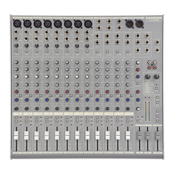
Page 8: Front Panel Layout
Front Panel Layout 53 54 55 56 57 58... -
Page 9: Front Panel Controls
Front Panel Controls FRONT PANEL right line input for the stereo channels. 1 MIC IN – Input connector for Low-Noise Microphone pre-amp. 22 LEFT/MONO LINE - 1/4-inch phone input connec- tor for the Left Line input for the stereo channels or a 2 LINE IN–Input connector for Line level inputs. -
Page 10: Front And Rear Panel Layout
Front and Rear Panel Layout FRONT PANEL CONTROLS - continued LEVEL control (35) to set the volume. 50 AUX RETURN 1 – Used to mix in the level of AUX Return 1. 42 POWER LED – Indicates the MDR1248 or MDR1688 is powered up. -
Page 11: Controls And Functions
Controls and Functions MONO INPUT CHANNEL SECTION 2 - LOW CUT FILTER - switch The following section details each part of the MDR1248 Each of the MDR1248 and MDR1688’s mono input chan- and MDR1688’s MONO INPUT CHANNELS including the nels include a LOW CUT (or high pass) filter which rolls off GAIN control, LOW CUT switch, 3-BAND EQ, AUX sends, the low frequencies from 75Hz and below at the rate of PEAK LED, PAN, SOLO, ALT 3/4 bus and LEVEL controls. - Page 12 Controls and Functions MONO INPUT CHANNEL SECTION - continued a monitor send. When the PRE/POST switch is set to POST, the signal feeding AUX 1 is sent after the fader, so the Auxiliary Busses ( 4 - 6 ) channel Fader has an effect on that level, meaning the The MDR series include two auxiliary signal paths, or Aux level tracks up and down with the channel Fader.
- Page 13 Controls and Functions in any optional headphones plugged in to the PHONES it towards the left will cut the frequency by 15dB. The fre- connector located in the front panel jack field. If the quency centers, range of boost or cut, and equalizer type AFL/PFL MODE switch, located in the master section, is for each band are as follows: switched out, the signal is sent pre fader, so you can hear...
- Page 14 Controls and Functions Auxiliary Busses ( 16 - 18 ) Right stereo mix field. You can create a stereo image by panning some input signals to the left and others to the The MDR series include two auxiliary signal paths, or right.
- Page 15 Controls and Functions 27 - AUX RET 1 control knob MASTER SECTION This adjusts the amount of signal that is sent from the AUX 26 - 2 TRK LEVEL 1 RET jacks to the MAIN bus. The 2TK LEVEL control knob is used to set the volume 28 - AUX RET 2 control knob level of the source connected to the 2-track input.
-
Page 16: Controls And Functions
Controls and Functions MASTER SECTION (continued) output and will be adjusted by the CR / PHONES control fader. DSP with 256 presets. The presets are organized in sixteen Program banks, each with sixteen variations. The Variation 45 - Phantom Power LED control knob is used to select one of the sixteen variations This LED illuminates indicating that the 48 volt phantom for each of the sixteen DSP effect Programs. -
Page 17: Mdr1248 And Mdr1688 Input And Output Connections
MDR1248 and MDR1688 Input and Output Connections MONO INPUT CHANNELS - MIC and LINE INPUTS equalizer, compressor, noise gate, reverb and other audio devices. For more information on the channel INSERT Channels 1 through 4 on the MDR1248 and channels 1 points, see the section, “Using the Channel Insert Jacks”... - Page 18 MDR1248 and MDR1688 Input and Output Connections mix. You can also pan the channels hard left and right to cre- L - AUX RETURN 2 LEFT/RIGHT ate two mono buses. Keep in mind that using the 3/4 switch The AUX RETURN 2 LEFT/RIGHT are stereo inputs that are mutes the channel from the main mix, so use the ALT 3/4 bus generally used to connect the outputs of an effects proces- for a separate stereo, or two mono, zone mixes.
-
Page 19: Operating The Mdr1248 And Mdr1688
Operating the MDR1248 and MDR1688 NOTE: SETTING THE INPUT GAIN - When connecting a BASIC OPERATION microphone to channels 1 through 4 on the MDR1244 or The following section explains the basic operation of the 1 through 8 on the MDR1688, it’s a good idea to start with MDR1248 and MDR1688: the Gain Control turned all the way down. -
Page 20: Operating The Mdr1248 And Mdr1688
Operating the MDR1248 and MDR1688 Next, locate the AUX SEND 2 knob and turn it about to USING THE DIGITAL EFFECTS a little past “5” or half way. The MDR1248 and MDR1688 mixers feature a built-in, high quality, 24-bit Multi Effect Processor, offering studio Now, use the AUX RETURN 2 control knob to adjust grade digital effects. -
Page 21: Sending An Independent Mix To The Monitor Speakers
The diagram below shows a typical application for using a compressor (in this example a Samson C com opti) in the MDR1248 or MDR1688’s insertion point. NOTE: When the AUX1 PRE/POST switch is pressed in and set to “PRE”, the AUX 1 controls are "PRE-FADER SENDS"... -
Page 22: Using An External Effect
Operating the MDR1248 and MDR1688 USING AN EXTERNAL EFFECT PLAYING BACK A CD USING 2T TO MIX If you prefer to use an external device for effects process- ing, you can easily connect the unit using the MDR1248 The MDR1248 and MDR1688 has a dedicated input for and MDR1688 AUX 2 bus. -
Page 23: Mdr1248 And Mdr1688 System Set-Ups
MDR1248 and MDR1688 System Set-Ups MDR1248 and MDR1688 LIVE SOUND SET-UP... -
Page 24: Mdr1248 And Mdr1688 Recording Set-Up
MDR1248 and MDR1688 System Set-Ups MDR1248 and MDR1688 RECORDING SET-UP... -
Page 25: Mdr1248 And Mdr1688 Wiring Guide
MDR1248 and MDR1688 Wiring Guide CONNECTING THE MDR1248 and MDR1688 The are several ways to interface the MDR1248 and MDR1688 to support a variety of applications. The MDR1248 and MDR1688 features balanced inputs and outputs, so connecting balanced and unbalanced signals is possible. Unbalanced 1/4”... -
Page 26: Mdr1248 And Mdr1688 Specifications
MDR1248 and MDR1688 Specifications Mono input channels Microphone input electronically balanced, discrete input configuration Frequency response 10Hz to 45kHz Distortion (THD & N) 0.005% at 4dBu, 1kHz Gain range 0dB to +40dB (MIC) SNR (Signal to Noise Ratio) 105dB Line input electronically balanced Frequency response 10Hz to 45kHz... - Page 28 Samson Technologies Corp. 45 Gilpin Avenue Hauppauge, New York 11788-8816 Phone: 1-800-3-SAMSON (1-800-372-6766) Fax: 631-784-2201 www.samsontech.com...