Invacare Storm 3 Competition / FFH User Manual
Power wheelchair
Hide thumbs
Also See for Storm 3 Competition / FFH:
- Service manual (93 pages) ,
- Assembly instructions (2 pages)
Table of Contents
Advertisement
Quick Links
Advertisement
Table of Contents

Related Manuals for Invacare Storm 3 Competition / FFH


Summary of Contents for Invacare Storm 3 Competition / FFH
- Page 1 Yes, you can. ® Invacare® Storm³ Competition / FFH Power wheelchair User manual...
- Page 3 How can you get in touch with Invacare®? If you have any questions or need support, please contact your authorised Invacare® Dealer, who has the necessary know-how and equipment plus the special knowledge concerning your Invacare® product, and can offer you all-round satisfactory service. Should you wish to contact Invacare® directly, you can reach us in Europe at the following addresses and phone numbers.
- Page 4 +44 (0)1656 77 62 20 Pencoed uk@invacare.com Bridgend CF35 5AQ WWW: www.invacare.co.uk United Kingdom Invacare Mecc San s.r.l. +39 0445 38 00 59 Via dei Pini, 62 Fax: +39 0445 38 00 34 I - 36016 Thiene (VI) italia@invacare.com ITALIA WWW: www.invacare.it...
- Page 5 +46 (0)8 761 81 08 Fagerstagatan 9 sweden@invacare.com S-163 91 Spånga finland@invacare.com Sverige WWW: www.invacare.se Tillverkare: MÖLNDAL Invacare® Deutschland GmbH : +46 (0)31 86 36 00 Kleiststraße 49 Fax: +46 (0)31 86 36 06 D-32457 Porta Westfalica ginvacare@invacare.com Deutschland LANDSKRONA ...
-
Page 6: Table Of Contents
Table of Contents Chapter Page Introduction Important symbols in this manual ..................11 Important symbols found on the vehicle ................13 Type classification and permissible use................14 Indications..........................15 Usability............................15 Warranty ...........................16 Life expectancy........................16 Safety notes General safety notes .......................18 Safety information for using the wheelchair as a piece of sports equipment ....21 Safety information on electromagnetic interference ............22 Safety information on driving and freewheel mode.............23 Safety information regarding changes and modifications to the mobility device....25... - Page 7 5.3.1 Maximum obstacle height .....................31 5.3.2 Safety information when ascending obstacles .............31 5.3.3 The correct way to overcome obstacles ...............32 Driving up and down gradients....................33 Use on public roads ........................34 Pushing the wheelchair in freewheel mode Disengaging Motors ........................34 Remotes Adjusting the wheelchair to the user's seating posture Adjusting the armrests and the control panel..............36 8.1.1...
- Page 8 8.6.1.4 Adjusting the length of the footrest................55 8.6.2 Manually height adjustable legrest 90° - 0° ..............56 8.6.2.1 Swivelling the legrest outward and/or removing............56 8.6.2.2 Setting the angle......................57 8.6.2.3 Setting the end stop of the legrest................60 8.6.2.4 Adjusting the length of the legrest ................64 8.6.2.5 Adjusting the depth of the calf plate ................65 8.6.2.6...
- Page 9 10.2 Safety checks that should be performed by the user............82 11 Repair instructions 11.1 Repairing a flat tyre .........................84 11.1.1 Repairing a flat tyre at the back (tyre type 3.00-8") ............85 12 Transport 12.1 Transferring the wheelchair to a vehicle................88 12.2 Securing the wheelchair for transport without passengers ..........89 13 Refurbishment...
-
Page 10: Introduction
The decision whether the model is suitable for the user may only be taken by medical specialists with appropriate expertise. Invacare® or their statutory representatives can accept no liability in cases in which the wheelchair has not been adapted to suit the users’ handicaps. -
Page 11: Important Symbols In This Manual
This manual contains copyrighted information. This manual may not be reproduced or reprinted either partly or completely without previous written consent from Invacare® or its statutory representatives. We reserve the right to make any necessary alterations on the grounds of technical improvements. - Page 12 RISK OF CRUSHING! This symbol warns of a risk of crushing caused by being careless with heavy components. • Always follow the instructions to avoid injury to the user or damage to the product. Wear eye protection This symbol refers to the requirement for wearing eye protection, for example when working with batteries.
-
Page 13: Important Symbols Found On The Vehicle
Important symbols found on the vehicle This product has been supplied from an environmentally aware manufacturer. This product may contain substances that could be harmful to the environment if disposed of in places (landfills) that are not appropriate according to legislation. •... -
Page 14: Type Classification And Permissible Use
This wheelchair may not be used as a vehicle seat! • This wheelchair does not satisfy the requirements of ISO 7176-19:2001 and may not under any circumstances be used as a vehicle seat or to transport the user in a vehicle. •... -
Page 15: Indications
Indications The use of this mobility product is recommended for the following indications: • The inability or a greatly restricted ability to walk within the scope of the basic requirement to be able to move within one’s own four walls. •... -
Page 16: Warranty
• You should immediately contact an authorised Invacare® dealer if the usability of your power wheelchair is restricted due to: - the lighting system failing or being defective - reflectors falling off - worn thread or insufficient tyre pressure - damage to the armrests (e.g. torn armrest padding) - damage to the legrest hangers (e.g. - Page 17 are met. The estimated life expectancy can be exceeded if the product is carefully used and properly maintained, and provided technical and scientific advances do not result in technical limitations. The life expectancy can also be considerably reduced by extreme or incorrect usage. The fact that we estimate a life expectancy for this product does not constitute an additional warranty.
-
Page 18: Safety Notes
Safety notes READ WELL BEFORE OPERATION! General safety notes Danger of injury if mobility device is used in any other way than the purpose described in this manual! • Only ever use the mobility device in accordance with the instructions in this User's Manual (see chapter "Type classification and permissible use"... - Page 19 Danger of injury if the mobility device is switched off while driving, for example by pressing the On/Off Button or disconnecting a cable, due to it coming to an abrupt, sharp stop! • If you have to brake in an emergency, simply release the joystick which will bring you to a halt. (refer to the joystick operating manual for more information).
- Page 20 Danger of fire or breaking down due to electric devices being connected! • Do not connect any electric devices to your mobility device that are not expressly certified by Invacare® for this purpose. Have all electrical installations done by your authorised Invacare® Dealer.
-
Page 21: Safety Information For Using The Wheelchair As A Piece Of Sports Equipment
Afterwards, it is the responsibility of the wheelchair user himself to judge risks correctly and to act accordingly. Invacare® can not be held responsible in case of injury to the user or other persons, and will provide no warranty in case of damage to the wheelchair, which result from increased... -
Page 22: Safety Information On Electromagnetic Interference
Safety information on electromagnetic interference This electric vehicle was successfully tested in accordance with International standards as to its compliance with Electromagnetic Interference (EMI) regulations. However, electromagnetic fields, such as those generated by radio and television transmitters, and cellular phones can influence the functions of electric vehicles. -
Page 23: Safety Information On Driving And Freewheel Mode
Safety information on driving and freewheel mode Danger of injury if the wheelchair tips over! • Inclines and declines can only be travelled up to the maximum safe slope (see chapter "Technical specifications" from page 92). • Always return the backrest of your seat or the seat tilt to an upright position before ascending slopes. - Page 24 Danger of breaking down in adverse weather conditions, i.e. extreme cold, in an isolated area! • If you are a user with severely limited mobility, we advise that in the case of adverse weather conditions DO NOT attempt a journey without an accompanying attendant! Danger of injury if your foot slides off the footrest and gets caught underneath the wheelchair when it is in motion! •...
-
Page 25: Safety Information Regarding Changes And Modifications To The Mobility Device
EEC / MPG (Medical Devices Act) and only applies to the complete product. The CE marking is invalidated if components or accessories are replaced or added that have not been approved for this product by Invacare. In this case, the company that adds or replaces the components or accessories is responsible for the conformity assessment/ CE marking or for registering the wheelchair as a special design and for the relevant documentation. - Page 26 • Only use seating systems that have been approved by Invacare® for this power wheelchair. Electrical and electronic components which have not been approved by Invacare® for use with this mobility aid can cause fire hazards and lead to electromagnetic damage! •...
-
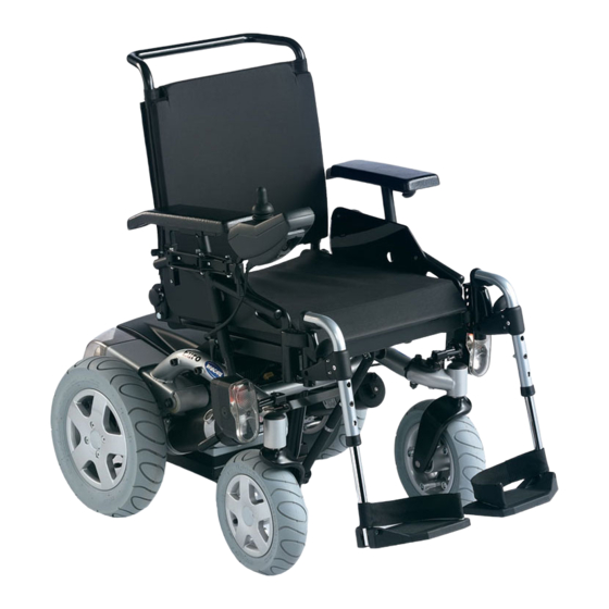
Page 27: Key Features
Key features 1) Sliding handle 2) Set screw for adjusting the height of the remote 3) Set screw for adjusting the angle of the backrest 4) Disengaging lever 5) Remote 6) Release button of the legrest... -
Page 28: Getting In And Out Of The Wheelchair
Getting in and out of the wheelchair Important information for getting into and out of the wheelchair from the side! The armrest must be removed in order to get into or out of the wheelchair from the side. Remove the standard armrest in order to side transfer Removing the armrest: •... - Page 29 Getting into the wheelchair: • Position your wheelchair as close as possible to your seat. This might have to be done by an attendant. • Switch your wheelchair off. • Apply the manual wheel lock of your wheelchair (if existing). •...
-
Page 30: Driving
Driving NOTE The maximum load capacity that is stated in the technical data only states that the system is designed for this mass in total. However, this does not mean that one can sit a person with this body weight in the wheelchair without restrictions. Attention must be paid to the body proportions, such as height, weight distribution, abdominal girth, leg and calf girth and seat depth. -
Page 31: Parking And Stationary
• The rear mirror (if installed) is adjusted so you can look behind at all times without having to bend forward or shift your seating position. Parking and stationary When parking your vehicle or if your vehicle is stationary for a prolonged period: •... -
Page 32: The Correct Way To Overcome Obstacles
5.3.3 The correct way to overcome obstacles Ascending Right • Approach the obstacle or the kerb slowly, head-on and at a right angle. • Depending on the wheel drive type, stop in one of the following positions: - In the case of centrally driven wheelchairs: 5 - 10 cm before the obstacle. - For all other drives: approx. -
Page 33: Driving Up And Down Gradients
Driving up and down gradients For information concerning the maximum safe slope, please see chapter "Technical specifications" starting on page 92. WARNING: Danger of tipping over! • Only ever drive downhill at a maximum of 2/3 of the top speed. Avoid sudden changes of direction or abrupt braking when driving on slopes. -
Page 34: Use On Public Roads
If you wish to use your wheelchair on public roads and lighting is required by national legislation, then your wheelchair needs to be equipped with an appropriate lighting system. Please contact your Invacare ® dealer if you have any questions. Pushing the wheelchair in freewheel mode The motors of the wheelchair are equipped with automatic brakes, preventing that the wheelchair starts rolling out of control when the joystick box is switched off. -
Page 35: Remotes
Declutching the motors: • Switch off the remote. • Pull the locking pin (1, on the underside of the declutching mechanism, not visible in the picture). Pull the coupling lever to the rear (2). The motors are declutched. Reclutching the motors: •... -
Page 36: Adjusting The Wheelchair To The User's Seating Posture
Adjusting the wheelchair to the user's seating posture Adjusting the armrests and the control panel 8.1.1 Adapting the control panel to the length of the user’s arm • Loosen the wing screw (1). • Set the remote to the desired length by pushing forward or backward. -
Page 37: Setting The Height Of The Remote
8.1.2 Setting the height of the remote • Loosen the wing screw (1). • Set the remote to the desired height. • Re-tighten the screw. -
Page 38: Setting The Height Of The Armrests
8.1.3 Setting the height of the armrests Requirements: • Allen key 3 mm • Use the Allen key 3 mm to loosen the screw (1). • Set the armrest at the desired height. • Re-tighten the screw. -
Page 39: Adjusting The Width Of The Armrests
8.1.4 Adjusting the width of the armrests The distance between the side sections can be adjusted by 5.5 cm on both sides (11 cm in total). Requirements: • Allen key 8 mm Where to find the adjustment screws The picture below shows the position of the screws (1) that enable adjustment to the width of the armrests. - Page 40 Doing the adjustment • Loosen the screw (1). • Set the armrest in the desired position. • Re-tighten the screw. • Check that the armrest is fastened firmly. • Repeat the procedure for the other armrest.
-
Page 41: Adjusting The Seat Angle / Seat Height
Adjusting the seat angle / seat height 8.2.1 Electric Please consult the user manual for your remote for information about electrical adjustment. 8.2.2 Manual adjustment using perforated plates There are three perforated plates underneath the seat for adjusting the seat angle and the seat height. - Page 42 • The picture at right shows the position of the perforated metal plates (1) and the fixation bolts (2) of the retaining plates for adjusting the seat height and seat angle. The picture at right shows the front perforated metal plates. The procedure is similar for the rear perforated metal plates.
- Page 43 Additionally, the seat height and angle can be adjusted using the rear retaining plates. • Loosen the rear fixation bolt on one side (in threaded bushing 1), so that the retaining plate can be swiveled upward or downward. • Loosen and remove the front fixation bolt (depending on the position, the bolt is either located in threaded bushing 2 or 3).
- Page 44 The adjustable rear perforated metal plates have five positions. These are indicated by the letters A to E in the illustration at right. When the retaining plates are in the lower position (see above), then all five adjustments can be used. In the high position, only adjustments B, C, D and E are possible! When using A, the retaining plate collides with the seat frame.
-
Page 45: Adjusting The Backrest
Adjusting the backrest 8.3.1 Adjusting the backrest manually The angle of the backrest has six positions, from -10° to +30°. • Loosen and remove the knurled screws (1) on both sides. • The backrest is adjusted by selecting a combination of one of the two drill holes in the backrest frame and one of the sechs drill holes in the fixation plate. -
Page 46: Adjusting The Headrest
Adjusting the headrest • Loosen the clamping lever (1, 2 or 3). • Adjust the headrest to the required position. • Retighten clamping lever. -
Page 47: Postural Belts
Postural belts A postural belt is an option which can either be fixed to the wheelchair ex-works or can be retrofitted by your specialist dealer. If your wheelchair is fitted with a postural belt, your specialist dealer will have informed you about fitting and usage. The postural belt is used to help the wheelchair user keep an optimum sitting position. - Page 48 Belt with metal buckle, adjustable both sides Belt can be adjusted on both sides. This means that the buckle can be centrally positioned. Harness with metal buckle, adjustable on both sides Harness can be adjusted on both sides. This ensures that the buckle is always centrally positioned.
-
Page 49: Adjusting The Postural Belt Correctly
If the belt is only fastened with a bolted connection, ensure that the connection has not loosened or undone. You can find more information about maintenance work on belts in the service manual, which is available from Invacare®. Legrests 8.6.1 Standard footrest with pre-set angle 8.6.1.1... -
Page 50: Setting The Angle
• Press the unlocking button (1) and swivel the footrest outward. • Remove the footrest in an upward direction. 8.6.1.2 Setting the angle PLEASE NOTE: Danger of injury due to incorrect adjustment of the footrests and legrests. • Before and during every journey it is imperative to ensure that the legrests contact neither the castor wheels nor the ground! Pre-requisites: •... - Page 51 • Loosen the screw (1) using the Allen key. • If the footrest cannot be moved after loosening the screw, position a metal pin in the designated borehole (2) and use a hammer to knock on this lightly. The clamping mechanism in the interior of the footrest will be released by this.
-
Page 52: Setting The End Stop Of The Footrest
8.6.1.3 Setting the end stop of the footrest Pre-requisites: • 1x 6 mm Allen key • 1x 10 mm open-ended spanner The end position of the footrest is determined by means of a rubber stop (1). The rubber stop can be screwed in or out (A) or pushed up or down (B). - Page 53 • Use the Allen key to loosen the screw (1) and swivel the footrest upward in order to access the rubber stop. • Use the open-ended spanner to loosen the counternut (1).
- Page 54 • Move the rubber stop to the desired position • Re-tighten the counternut • Move the footrest to the desired position. • Re-tighten the screw.
-
Page 55: Adjusting The Length Of The Footrest
8.6.1.4 Adjusting the length of the footrest PLEASE NOTE: Danger of injury due to incorrect adjustment of the footrests and legrests. • Before and during every journey it is imperative to ensure that the legrests contact neither the castor wheels nor the ground! Pre-requisites: •... -
Page 56: Manually Height Adjustable Legrest 90° - 0
8.6.2 Manually height adjustable legrest 90° - 0° 8.6.2.1 Swivelling the legrest outward and/or removing The small unlocking button is located on the upper section of the legrest. When the legrest is unlocked, it can be swivelled inward or outward when getting into wheelchair as well as being removed completely. -
Page 57: Setting The Angle
8.6.2.2 Setting the angle PLEASE NOTE: Danger of injury due to incorrect adjustment of the footrests and legrests. • Before and during every journey it is imperative to ensure that the legrests contact neither the castor wheels nor the ground! •... - Page 58 • Hit the knob to release the locking mechanism. • Set the desired angle.
- Page 59 • Turn the knob clockwise to tighten it.
-
Page 60: Setting The End Stop Of The Legrest
8.6.2.3 Setting the end stop of the legrest Pre-requisites: • 1x 10 mm open-ended spanner The end position of the legrest is determined by means of a rubber stop (A). The rubber stop can be screwed in or out (A) or pushed up or down (B). - Page 61 • Loosen the locking knob (1) counter-clockwise at least one turn. • Hit the knob to release the locking mechanism.
- Page 62 • Swivel the legrest upward in order to access the rubber stop. • Use the open-ended spanner to loosen the counternut (1).
- Page 63 • Move the rubber stop to the desired position • Re-tighten the counternut • Move the legrest to the desired position. • Re-tighten the locking knob.
-
Page 64: Adjusting The Length Of The Legrest
8.6.2.4 Adjusting the length of the legrest PLEASE NOTE: Danger of injury due to incorrect adjustment of the footrests and legrests. • Before and during every journey it is imperative to ensure that the legrests contact neither the castor wheels nor the ground! Pre-requisites: •... -
Page 65: Adjusting The Depth Of The Calf Plate
8.6.2.5 Adjusting the depth of the calf plate The depth of the calf plate can be adjusted via the holding plate. The holding plate hole combinations allow 5 different depth settings. Pre-requisites: • 1x 10 mm open-ended spanner • Use the open-ended wrench to loosen the nut (1) and remove. -
Page 66: Adjusting The Height Of The Calf Pad
8.6.2.6 Adjusting the height of the calf pad Pre-requisites: • 1x 4 mm Allen key • Use the Allen key to loosen the screws (1). • Adjust to the desired position. • Re-tighten the screws. -
Page 67: Unlocking And Swivelling The Calf Plate Backward When Alighting
8.6.2.7 Unlocking and swivelling the calf plate backward when alighting • Press the calf plate straight down. • Unlock the legrest and swivel outward. The calf plate swivels backward on its own. -
Page 68: Adjusting The Angle Adjustable Foot Plate
• Lift leg over the heel strap and place on the ground. 8.6.2.8 Adjusting the angle adjustable foot plate Pre-requisites: • 1x 5 mm Allen key • Use the Allen key to loosen both set screws on the foot plate. •... -
Page 69: Adjusting The Angle And Depth Adjustable Foot Plate
8.6.2.9 Adjusting the angle and depth adjustable foot plate Pre-requisites: • 1x 5 mm Allen key • Use the Allen key to loosen the set screw on the foot plate (1). • Adjust the foot plate to the desired angle or depth. -
Page 70: Electrical System
Electrical system Electronics protection system The vehicle's electronics are equipped with an overload-protection system. If the motors are put under considerable strain for a longer period of time (for example, when driving up a steep hill) and especially when the ambient temperature is high, then the electronic system could overheat. -
Page 71: The Main Fuse
NOTE A defective main fuse may be replaced only after checking the entire electric system. An Invacare® specialised dealer must perform the replacement. You can find information on the fuse type in chapter "Technical specifications" starting on page 92. The entire electric system of the wheelchair is protected by the main fuse against overloading. -
Page 72: Batteries
Batteries Power is supplied by two 12 V batteries. The batteries are maintenance-free and only need regular charging. In the following, you find information on how to charge, handle, transport, store, maintain, and use batteries. 9.2.1 Charging the batteries 9.2.1.1 General information on charging New batteries should always be fully charged once before their first use. -
Page 73: How To Charge The Batteries
10 °C. • Use only charging devices in Class 2. This class of chargers may be left unattended during charging. All charging devices which are supplied by Invacare® comply with these requirements. •... -
Page 74: How To Disconnect The Batteries After Charging
Risk of explosion and destruction of batteries if the wrong battery charger is used! • Only ever use the battery charger supplied with your vehicle, or a charger that has been approved by Invacare®. Risk of electric shock and damage to the battery charger if it gets wet! •... -
Page 75: Storage And Maintenance
9.2.2 Storage and Maintenance Follow the instructions listed below to ensure safe use and longevity of the batteries: • Always store the batteries fully charged. • Do not leave the batteries in a low state of charge for an extended length of time. Charge a discharged battery as soon as possible. - Page 76 The last 3 LED (two red and one orange) mean a remaining capacity of about 15 %. • Driving with blinking red LED’s means an extreme stress for the battery and should be avoided under normal circumstances. • When only one red LED is blinking, the Battery Safe feature is enabled. From this time, speed and acceleration is reduced drastically.
-
Page 77: Transporting Batteries
• Under normal operation, once a month the battery should be discharged until all green and orange LED are off. This should be done within one day. A 16 hour charge afterwards is necessary as reconditioning. 9.2.4 Transporting batteries The batteries supplied with your electric vehicle are not hazardous goods. This classification is based on the German GGVS Hazardous Goods Road Transport Ordinances, and the IATA/DGR Hazardous Goods Rail Transport / Air Transport Ordinances. - Page 78 Only ever transport damaged batteries in an appropriate acid-resistant receptacle. • Wash all objects that have come into contact with acid with lots of water. Disposing of dead or damaged batteries correctly Dead or damaged batteries can be given back to your dealer or directly to Invacare®.
-
Page 79: Removing The Batteries
9.2.5.3 Removing the batteries CAUTION: Risk of fire and burns if battery poles are bridged! • When replacing the batteries the battery poles MUST NOT come into contact with metal parts of the wheelchair causing bridging. • Be sure to replace the battery pole caps after the batteries have been replaced. Pre-requisites: •... - Page 80 • Remove the plastic clips (1) pull the electronic device support backwards and upwards. • Pull the battery pole caps (1) upward and push back in order to reach the battery poles. • Use the open-ended spanner to loosen the battery pole clamp (2).
-
Page 81: Care And Maintenance
Maintenance encompasses different areas, such as everyday care and cleaning, inspection checks, repair tasks and refurbishment. NOTE: Have your vehicle checked at least twice a year by an authorised Invacare® dealer in order to maintain it's driving safety and roadworthiness. 10.1... -
Page 82: Safety Checks That Should Be Performed By The User
10.2 Safety checks that should be performed by the user Explanation of the symbols: During normal use, as well as during use as a piece of sports equipment Especially during use as a piece of sports equipment Maintenance Jobs Seat and backrest padding: - Check for perfect condition. - Page 83 A complete checklist of necessary maintenance work can be found in the Service Manual, which can be obtained from Invacare®.
-
Page 84: Repair Instructions
"Technical specifications" on page 92, or consult the Service Manual, available from Invacare® (in this connection please see the addresses and phone numbers in section "How can you get in touch with Invacare®?" on page 3). In case you require assistance, please contact your Invacare® Dealer. -
Page 85: Repairing A Flat Tyre At The Back (Tyre Type 3.00-8")
11.1.1 Repairing a flat tyre at the back (tyre type 3.00-8") Injury hazard! If the wheel has been insufficiently secured during assembly, it can become loosened during driving! • When refitting the drive wheels, tighten the Torx screw that secures the wheel to the hub to a torque of 30 Nm! •... - Page 86 Removing the wheel • Jack the vehicle up and place a block of wood underneath it to prop it up. • Remove the countersunk screw (1) using the Torx bit. • Remove the wheel from the axle. EXPLOSION HAZARD! The wheel will explode if the air pressure is not released from the tyre before disassembling the wheel rim! •...
- Page 87 NOTE In case the old inner tube is to be repaired and used again, and it happens to get wet during repair, then it is easier to re-fit it if you powder it lightly with talcum powder. NOTE Re-assembly is done in reverse order. Make sure that the wheel is put back on the same side it was on, and that it runs in the same direction it did before it was removed.
-
Page 88: Transport
Transport 12.1 Transferring the wheelchair to a vehicle WARNING: The wheelchair is in danger of tipping over if it is transferred to a vehicle while the driver is still seated in the wheelchair! • Transfer the wheelchair without the driver whenever possible! •... -
Page 89: Securing The Wheelchair For Transport Without Passengers
Securing the wheelchair for transport without passengers CAUTION: Injury hazard! ® • If you are unable to fasten your electric wheelchair securely in a transport vehicle, Invacare recommends that you do not transport it! • Before transporting your wheelchair, make sure the motors are engaged and that the Joystick Box is switched off. -
Page 90: Refurbishment
Cleaning and disinfection. Please see chapter "Care and maintenance" on page 81. • Inspection according to service plan. Please consult service instructions, available from Invacare®. • Adaptation to the user. Please see chapter "Adjusting the wheelchair to the user's seating... -
Page 91: Disposal
Electric components and printed circuit boards are disposed of as electronic scrap. • Exhausted or damaged batteries can be returned to your medical equipment supplier or Invacare®. • Disposal must be carried out in accordance with the respective national legal provisions. -
Page 92: Technical Specifications
Technical specifications The technical information provided hereafter applies to a standard configuration or represents maximum achievable values. These can change if accessories are added. The precise changes to these values are detailed in the sections for the respective accessories. Permissible operating and storage conditions Temperature range for operation according to ISO 7176-9: •... - Page 93 Castor wheel tyres Tyre type • 200x50 puncture-proof Driving features Speed • 10 km/h Min. braking distance • 2100 mm Max. safe slope ****** • 10° (18 %) according to manufacturer’s specifications with 120 kg payload, 4° seat angle, 20° backrest angle Max.
- Page 94 **** Measured without seat cushion ***** The actual kerb weight depends on the fittings your mobility aid has been supplied with. Every Invacare® mobility aid is weighed when leaving the works. Please refer to the nameplate for the kerb weight (including batteries) measured.
-
Page 95: Inspections Performed
It is confirmed by stamp and signature that all jobs listed in the inspection schedule of the Service and Repair Instructions have been properly performed. The list of the inspection jobs to be performed can be found in the Service Manual which is available through Invacare®. Delivery Inspection...