Table of Contents
Advertisement
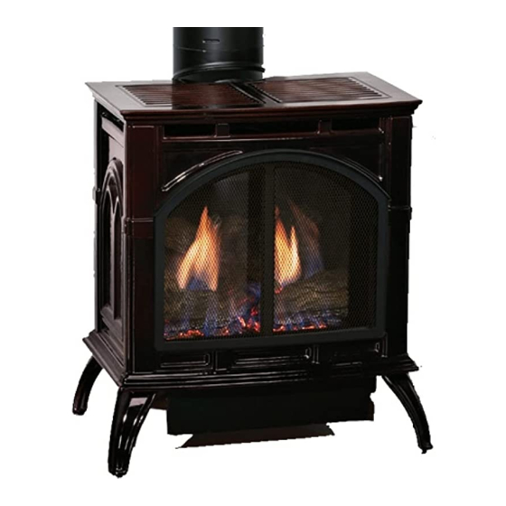
Comfort Systems
The Heritage Cast Iron Stoves
WARNING
Installer:
Leave this manual with the appliance.
Consumer: Retain this manual for future reference.
If the information in these instructions are not fol-
ing property damage, personal injury or loss of life.
vapors and liquids in the vicinity of this or any
other appliance.
— WHAT TO DO IF YOU SMELL GAS
any phone in your building.
neighbor's phone. Follow the gas supplier's
instructions.
— Installation and service must be performed by a
plier.
INSTALLATION INSTRUCTIONS
HOT GLASS
WILL
CAUSE BURNS.
DO NOT TOUCH
GLASS
UNTIL COOLED.
NEVER
ALLOW CHILDREN
TO TOUCH GLASS.
WARNING
AND
OWNER'S MANUAL
DIRECT VENT STOVE
DVP20CC(30,70)(B,F,M)(N,P)-1
DVP30CC(30,70)(B,F,M,S,W)(N,P)-1
This appliance may be installed in an aftermarket
permanently located, manufactured home (USA only) or
mobile home, where not prohibited by local codes.
This appliance is only for use with the type of gas
indicated on the rating plate. This appliance is not
-
kit is used.
Improper installation, adjustment, alteration, service
or maintenance can cause injury or property damage.
Refer to this manual. For assistance or additional in-
or the gas supplier.
-
CAST IRON
MODELS:
GAS-FIRED
WARNING
Page 1
Advertisement
Table of Contents
Troubleshooting

Related Manuals for Empire Comfort Systems DVP20CC Series


Summary of Contents for Empire Comfort Systems DVP20CC Series
-
Page 1: Installation Instructions
INSTALLATION INSTRUCTIONS OWNER'S MANUAL Comfort Systems The Heritage Cast Iron Stoves CAST IRON DIRECT VENT STOVE MODELS: DVP20CC(30,70)(B,F,M)(N,P)-1 DVP30CC(30,70)(B,F,M,S,W)(N,P)-1 GAS-FIRED WARNING HOT GLASS WILL CAUSE BURNS. DO NOT TOUCH GLASS UNTIL COOLED. NEVER ALLOW CHILDREN TO TOUCH GLASS. Installer: Leave this manual with the appliance. This appliance may be installed in an aftermarket Consumer: Retain this manual for future reference. -
Page 2: Table Of Contents
TABLE OF CONTENTS SECTION PAGE IMPORTANT SAFETY INFORMATION ..................3 SAFETY INFORMATION FOR USERS OF LP-GAS..............4 REQUIREMENTS FOR MASSACHUSETTS ................5 INTRODUCTION ........................... 6 SPECIFICATIONS ......................... 7 GAS SUPPLY ..........................8 CLEARANCES ......................... 9-10 VENTING STOVE........................11-12 TERMINATION CLEARANCES ....................13 VENT CLEARANCES ........................ -
Page 3: Important Safety Information
IMPORTANT SAFETY INFORMATION Before enclosing the vent pipe assembly, operate the appliance to ensure it is venting properly. DO NOT OPERATE THIS APPLIANCE WITHOUT GLASS FRONT PANEL INSTALLED continuous surface (e.g. wood, metal, concrete). and proper operation. a platform to enhance its visual impact. The appliance may be installed on carpeting, tile, appliance. -
Page 4: Safety Information For Users Of Lp-Gas
SAFETY INFORMATION FOR USERS OF LP-GAS with the members of your household. Someday when there and explosions. In its natural state, propane is odorless and may not be a minute to lose, everyone's safety will depend colorless. You may not know all the following safety precautions on knowing exactly what to do. -
Page 5: Requirements For Massachusetts
REQUIREMENTS FOR MASSACHUSETTS “GAS VENT DIRECTLY 30794-0-0812 Page 5... -
Page 6: Introduction
INTRODUCTION Instructions to Installer State of Massachusetts: National Fuel Gas Code ANSI Z223.1/NFPA 54* Natural Gas and Propane Installation Code, or CSA B149.1 in Canada.*Available from the American National Standards Institute, Inc. 11 West 42nd St., New York, N.Y. 10036. WARNING WARNING ANY CHANGE TO THIS STOVE OR ITS CONTROLS CAN... -
Page 7: Specifications
SPECIFICATIONS Model DVP20CC DVP30CC 19,500 26,500 26,500 13,500 18,000 21,000 DVKHP 46DVA-WT, 46DVA-HC, 46DVA-E90B) DVK45LP DVK45NAT 46DVADC, SD46DVAWT, SD46DVAHC) DVKVP45 SD46DVAE90B, SD46DVA12B, SD46DVA911B, SD46DVADC, SD46DVAWT, SD46DVAHC) Accessories FRBC FRBTC FREC FRBTP CIB3 CIB4 Stone Inlay Replaces Standard Grill Top - DVP30CC30 Models ONLY CSI-8V CSI-9A CSI-10M... -
Page 8: Gas Supply
GAS SUPPLY Installing a New Main Gas Cock Recommended Gas Pipe Diameter Schedule 40 Pipe Tubing, Type L Pipe Length Inside Diameter Outside Diameter L.P. L.P. be disconnected from piping at inlet of control valve and pipe capped or plugged for pressure test. Never pressure test with Note: Note: Note:... -
Page 9: Clearances
CLEARANCES 4” (102mm) H 10” VP20 (254mm) 14” VP30 (355mm) Locating and Venting the Direct Vent Stove Installation on Rugs and Tile 4” (102mm) 36” (91cm) T PP I 6” (153mm) T 6” (153mm) T : H T 45° Figure 3 Figure 2 2”... - Page 10 CLEARANCES (cont.) Special Vent Systems Simpson Duravent® GS American Metal® 4" - 6 5/8" Selkirk Direct-Temp® 4" - 6 5/8" Security Secure Vent® ICC Inc. Excel American Metal®, Selkirk Direct-Temp®, Security Secure Vent®, and ICC Inc. Excel CAN NOT be used in side wall horizontal vent installations in the state of Massachusetts.
-
Page 11: Venting Stove
VENTING STOVE SPECIAL VENTING NOTES: Venting Graph (Dimensions in Feet) DVP20CC NAT DVP20CC LP DVP30CC - CAN NOT DVP30CC NAT DVP30CC LP Note: Venting Requirements Sidewall Venting To Use the Vent Graph EXAMPLE A: CAUTION Horizontal chimney run must slope upward (away from stove) 1/4"... - Page 12 VENTING STOVE (cont.) 1 2 3 4 5 6 7 8 9 10 11 12 13 14 1 2 3 4 5 6 7 8 9 10 11 12 13 14 24” 28” Figure 7a - DVP20CC Figure 7b - DVP30CC Page 12 30794-0-0812...
-
Page 13: Termination Clearances
TERMINATION CLEARANCES Figure 8 Vertical Sidewall Installations Important! Important! Information on Various Venting Routes and Components Important: 30794-0-0812 Page 13... -
Page 14: Vent Clearances
VENT CLEARANCES Figure 9 Note: Page 14 30794-0-0812... -
Page 15: Vent System Identification
VENT SYSTEM IDENTIFICATION Installing Vent Components PART NAME "A" "B" "C" Figure 11 Figure 10 30794-0-0812 Page 15... -
Page 16: Framing And Finishing
FRAMING AND FINISHING Installing Support Brackets MI IM M 1” (25.4mm) Figure 13 T PIP 48” (1219mm) Note: Figure 12 Installing Firestops Figure 14 Page 16 30794-0-0812... -
Page 17: Horizontal Termination
FRAMING AND FINISHING (continued) Figure 15 Figure 16 HORIZONTAL TERMINATION Note: WARNING Termination cap must be positioned so that the arrow is pointing up. NOTE: CAUTION it is necessary to install the vinyl siding shield (46DVA-VSS). Figure 17 30794-0-0812 Page 17... -
Page 18: Vertical Termination
VERTICAL TERMINATION Vertical Terminations Note: Figure 19. General Maintenance Determining Minimum Vent Height Above the Roof. WARNING Major U.S. building codes specify minimum chimney and/or vent height above the roof top. These minimum heights are summarized in Figure 18. Installing the Vent System in a Chase H (MINIMUM ROOF PITCH FEET... - Page 19 VERTICAL TERMINATION (continued) Installing Support Brackets Note: Vertical Through the Roof Applications LISTED CA LISTED GAS ENT Reassembly and Resealing Vent-Air Intake System STOR COLLAR ROOF FLASHING CEILING FIRESTO ’ 4 CEILING OIST AXI U Figure 21 30794-0-0812 Page 19...
-
Page 20: Log Identification
LOG IDENTIFICATION Part Number Log Photo (Front Views) Description DVP20CC DVP30CC REAR LOG 29790 29795 RIGHT LOG 29792 29797 LEFT LOG 29791 29796 TOP BRANCH 29793 TOP BRANCH 29798 Page 20 30794-0-0812... -
Page 21: Log Placement
LOG PLACEMENT Figure 22 Figure 23 - Log Placement - Top View (DVP20CC Shown) Figure 24 - Log Placement - Front View (DVP20CC Shown) 30794-0-0812 Page 21... -
Page 22: Operating Instructions
OPERATING INSTRUCTIONS 750 Millivolt System Initial Lighting Pilot Flame WARNING During the initial purging and subsequent lightings, never allow the gas valve control knob to remain depressed in the least once every second. NOTICE: Figure 25 Figure 26 Figure 25 Page 22 30794-0-0812... -
Page 23: Main Burner Flame Characteristics
MAIN BURNER FLAME CHARACTERISTICS Cleaning the Log Set and Firebox Cleaning and Maintenance / Main Burner WARNING CAUTION The ceramic logs are durable when handled and installed properly. However, they are delicate and may be damaged easily if not handled with care. Handling damage to the ceramic logs is not covered by warranty. -
Page 24: Wiring
WIRING DVP(20,30)CC ON/OFF/REMOTE Switch REMOTE Note: Operation of ON/OFF/REMOTE Switch with no Accessories Manual Operation Operation of ON/OFF/REMOTE Switch with Accessories 750 Millivolt Wall Thermostat Wall Thermostat Operation OFF. RECOMMENDED WIRE GAUGES Maximum Wire Installation of Remote Receiver Length Gauge Wall Switch, FWS EMOTE REMOTE... -
Page 25: Millivolt Lighting Instructions
MILLIVOLT LIGHTING INSTRUCTIONS FOR YOUR SAFETY READ BEFORE LIGHTING result causing property damage, personal injury or loss of life. A. This appliance has a pilot which must be lighted by hand. When lighting the pilot, follow these instructions exactly. department. B. -
Page 26: Millivolt Wiring
MILLIVOLT WIRING Optional Wall Switch For Standing Pilot Ignition Wiring Appliance Requirements WARNING DO NOT CONNECT 110-120 VAC TO THE GAS CONTROL WARNING VALVE OR THE APPLIANCE WILL MALFUNCTION AND THE DO NOT CONNECT THE 110-120 VAC TO THE WALL SWITCH VALVE WILL BE DESTROYED. -
Page 27: Millivolt Troubleshooting
MILLIVOLT TROUBLESHOOTING With proper installation and maintenance, your new Direct Vent Stove should provide years of trouble-free service. If you do ex- of problems and the corrective action to be taken. Spark ignitor will not light pilot after repeated depressing of piezo ignitor button. -
Page 28: Ip Operating Instructions
IP OPERATING INSTRUCTIONS Attention: For shipping purposes, the Electronic Control Module and Receiver Plate assembly is loosely packaged near the left side of the appliance. It is necessary that the re- appliance at the time of installation. To secure, remove the and secure with the two screws previously removed. -
Page 29: Ip Electronic System Wiring Diagram
IP ELECTRONIC SYSTEM WIRING DIAGRAM CPI/IPI SWITCH ON/OFF REMOTE RECEIVER PILOT SWITCH (OPTIONAL) + ON REMOTE - OFF GAS CONTROL VALVE (GND) AC/DC POWER ADAPTOR ELECTRONIC CONTROL MODULE BATTERY HOLDER CAUTION Do not operate the appliance with panel(s) removed, cracked or broken. Replacement of the panel(s) should be done by a WARNING 30794-0-0812 Page 29... -
Page 30: Intermittent Pilot Lighting Instructions
INTERMITTENT PILOT LIGHTING INSTRUCTIONS FOR YOUR SAFETY READ BEFORE LIGHTING LIGHTING INSTRUCTIONS Note ELECTRODE ILOT FLA E SENSOR TO TURN OFF GAS TO FIREPLACE Page 30 30794-0-0812... -
Page 31: Intermittent Control System Troubleshooting
INTERMITTENT CONTROL SYSTEM TROUBLESHOOTING Brief Description of the Components Troubleshooting WARNING Any actions performed on the gas valve must be performed in accordance with this instruction manual. Likewise, any actions performed on the DFC or other system components must be done in accordance with the individual component instructions. - Page 32 INTERMITTENT CONTROL SYSTEM TROUBLESHOOTING If the F giving signal lock out: Verify the electrical connections integrity and The board should be unlocked to make sure they are in accordance with the relevant reinitiate a pilot flame ignition (for Is the F board in system wiring diagram.
- Page 33 INTERMITTENT CONTROL SYSTEM TROUBLESHOOTING eplace F board. Main burner lights when the pilot only eplace the gas valve. should light. Verify the pilot flame fully engulfs the tip of the sense electrode. If not replace the pilot assembly. eplace the pilot assembly. arefully clean the electrical connections of the sense cable, and the F board sense cable connection.
-
Page 34: Maintenance
MAINTENANCE SHOWN WITH TO FRONT RE O ED Glass Cleaning GLASS FRA E ASSE BL General Glass Information LATCH GLASS FRA E WARNING WITH GLASS FRA E Figure 31 IMPORTANT: put anything around the heater that will obstruct examine venting system periodically. Clean and replace damaged parts. -
Page 35: Maintenance And Service
MAINTENANCE AND SERVICE Cleaning Cleaning Glass Door Frequency: IMPORTANT: TURN OFF THE GAS BEFORE SERVICING YOUR APPLIANCE. Cleaning Burner and Controls Task: Frequency: Task: CAUTION Use only ammonia free, nonabrasive glass cleaners. Checking Flame Patterns, Flame Height Frequency: CAUTION DO NOT handle or attempt to clean the door when it is hot Task: and DO NOT use abrasive cleaners. -
Page 36: Dvp20Cc(30,70)Parts List
DVP20CC(30,70)PARTS LIST PART NUMBER INDEX DESCRIPTION DVP20CC30 DVP20CC30 DVP20CC70 DVP20CC70 R9672 R9672 R9672 R9672 INLET VENT COLLAR M178 M178 M178 M178 INLET COLLAR GASKET 30602 30602 30602 30602 AIR DROP ASSEMBLY M163 M163 M163 M163 FLUE OUTLET GASKET 30392 30392 30392 30392 BLOW PLATE BRACKET... -
Page 37: Dvp20Cc(30,70)Parts View
DVP20CC(30,70)PARTS VIEW VP20 VP30 USE ONLY MANUFACTURER'S REPLACEMENT PARTS. USE OF ANY OTHER PARTS COULD CAUSE INJURY OR DEATH. 30794-0-0812 Page 37... -
Page 38: Dvp30Cc(30,70) Parts List
DVP30CC(30,70) PARTS LIST PART NUMBER INDEX DESCRIPTION DVP30CC30 DVP30CC30 DVP30CC70B DVP30CC70B R9672 R9672 R9672 R9672 INLET VENT COLLAR M178 M178 M178 M178 INLET COLLAR GASKET 30892 30892 30892 30892 AIR DROP ASSEMBLY M163 M163 M163 M163 FLUE OUTLET GASKET 30392 30392 30392 30392... -
Page 39: Dvp30Cc(30,70) Parts View
DVP30CC(30,70) PARTS VIEW VP20 VP30 USE ONLY MANUFACTURER'S REPLACEMENT PARTS. USE OF ANY OTHER PARTS COULD CAUSE INJURY OR DEATH. 30794-0-0812 Page 39... -
Page 40: Casting Parts List
CASTING PARTS LIST PART NO. INDEX PART NO. INDEX DESCRIPTION DESCRIPTION DVP20CC DVP30CC DVP20CC DVP30CC COMMON PARTS INSERT TAB VENT OPENING INSERT R9671 R9671 R11355 (4 REQUIRED) MIDDLE HINGE PIN R9570 TOP INSERT - RIGHT R9669 (4 REQUIRED) R9569 TOP INSERT - LEFT R9670 R9670 R11314... -
Page 41: Casting Parts View
CASTING PARTS VIEW USE ONLY MANUFACTURER'S REPLACEMENT PARTS. USE OF ANY OTHER PARTS COULD CAUSE INJURY OR DEATH. 30794-0-0812 Page 41... -
Page 42: Master Parts Distributor List
For the current list, please click on the Master Parts button at www.empirecomfort.com. Please note: Master Parts Distributors are independent businesses that stock the most commonly ordered Original Equipment repair parts for Heaters, Grills, and Fireplaces manufactured by Empire Comfort Systems Inc. Dey Distributing... -
Page 43: Accessory Side Shelves Installation Instructions
ACCESSORY SIDE SHELVES INSTALLATION INSTRUCTIONS Installing Accessory Side Shelves: Note: Figure 33 Note: Figure 34 WASHER LACE ENT OUTSIDE OF TO CASTING SIDE BOLT Figure 32 WASHER LACE ENT CENTER SIDE OF BOLT BOTTO Figure 35 30794-0-0812 Page 43... -
Page 44: Cib3-1 Optional Blower Installation Instructions - Dvp30Cc
CIB3-1 OPTIONAL BLOWER INSTALLATION INSTRUCTIONS - DVP30CC Installing Optional CIB3 Blower CAUTION Sharp edges, use protective gloves when installing. Carton Contents Note: Hardware Package SCREW Note AUTO/ON/OFF SWITCH KNOB Page 44 30794-0-0812... - Page 45 CIB3-1 OPTIONAL BLOWER INSTALLATION INSTRUCTIONS - DVP30CC Fan Control Wiring National Electrical Code, ANSI/NFPA 70 or Canadian Electrical Code, CSA C22.1 This appliance is equipped with a three-prong [grounding] plug for your protection against shock hazard and should be plugged AUTO/OFF/ON SWITCH directly into a properly grounded three-prong receptacle.
-
Page 46: Cib3-1 Optional Blower Installation Instructions - Dvp30Cc
CIB3-1 OPTIONAL BLOWER INSTALLATION INSTRUCTIONS - DVP30CC PARTS LIST INDEX NUM- PART NUM- DESCRIPTION R1454 BRASS BUSHING R1499 RUBBER GROMMET 24231 BLOWER HOUSING R1410 STRAIN RELIEF BUSHING R9927 BLOWER ASSEMBLY 24225 BLOWER COVER R6159 CORD SET R10363 WIRE HARNESS R2503 FAN CONTROL 24222 FAN CONTROL BRACKET... -
Page 47: Cib4-1 Optional Blower Installation Instructions - Dvp20Cc
CIB4-1 OPTIONAL BLOWER INSTALLATION INSTRUCTIONS - DVP20CC Installing Optional CIB4 Blower CAUTION Sharp edges, use protective gloves when installing. Carton Contents Hardware Package 10 x 1/2” / FF IT H Installing Optional CIB4 Blower 30794-0-0812 Page 47... - Page 48 CIB4-1 OPTIONAL BLOWER INSTALLATION INSTRUCTIONS - DVP20CC Fan Control Wiring National Electrical Code, ANSI/NFPA 70 or Canadian Electrical Code, CSA C22.1 This appliance is equipped with a three-prong [grounding] plug for your protection against shock hazard and should be plugged Cleaning directly into a properly grounded three-prong receptacle.
-
Page 49: Cib4-1 Optional Blower Installation Instructions - Dvp20Cc
CIB4-1 OPTIONAL BLOWER INSTALLATION INSTRUCTIONS - DVP20CC PARTS LIST INDEX NUMBER PART NUMBER DESCRIPTION R1454 R1499 CI002 R1517 R2804A CI003 R2099 R3767A 24222 R2503 R2805 R1410 30794-0-0812 Page 49... -
Page 50: Warranty
WARRANTY Limited Lifetime Parts Warranty – Combustion Chamber, Heat Exchanger, and Factory-Installed Glass Limited Three-Year Parts Warranty – All Other Components Limited One-Year Parts Warranty – Remote Controls, Thermostats, Accessories, and Parts Duties Of The Owner What Is Not Covered How To Get Service Your Rights Under State Law Page 50... -
Page 51: Appliance Service History
APPLIANCE SERVICE HISTORY Date Dealer Name Service Technician Name Service Performed/Notes 30794-0-0812 Page 51... - Page 52 APPLIANCE SERVICE HISTORY Date Dealer Name Service Technician Name Service Performed/Notes Page 52 30794-0-0812...
-
Page 53: Appliance Service History
APPLIANCE SERVICE HISTORY Date Dealer Name Service Technician Name Service Performed/Notes 30794-0-0812 Page 53... -
Page 54: Quick Reference Guide
Comfort Systems The Heritage Cast Iron Stoves GAS-FIRED Models: DVP20CC(30,70)(B,F,M)(N,P)-1 DVP30CC(30,70)(B,F,M,S,W)(N,P)-1 Model DVP20CC DVP30CC 19,500 26,500 26,500 13,500 18,000 21,000 Page 54 30794-0-0812... - Page 55 Comfort Systems The Heritage Cast Iron Stoves GAS-FIRED Models: DVP20CC(30,70)(B,F,M)(N,P)-1 DVP30CC(30,70)(B,F,M,S,W)(N,P)-1 CLEARANCES Locating and Venting the Direct Vent Stove Installation on Rugs and Tile 36” (91cm) T 36” (91cm) T PP I PP I 6” (153mm) T 6” (153mm) T 6”...
- Page 56 Comfort Systems www.empirecomfort.com Page 56 30794-0-0812...