Table of Contents
Advertisement
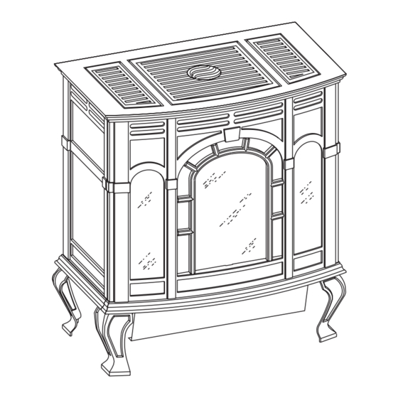
The Classic Cast Iron Stoves
Installer:
Leave this manual with the appliance.
Consumer:
Retain this manual for future reference.
This appliance may be installed in an aftermarket permanently
located, manufactured home (USA only) or mobile home,
where not prohibited by local codes.
This appliance is only for use with the type of gas indicated
on the rating plate. This appliance is not convertible for use
with other gases, unless a certified kit is used.
WARNING: If the information in these instructions are
not followed exactly, a fire or explosion may result caus-
ing property damage, personal injury or loss of life.
— Do not store or use gasoline or other flammable vapors
and liquids in the vicinity of this or any other appli-
ance.
— WHAT TO DO IF YOU SMELL GAS
•
Do not try to light any appliance.
•
Do not touch any electrical switch; do not use any
phone in your building.
•
Immediately call your gas supplier from a neigh-
bor's phone. Follow the gas supplier's instruc-
tions.
•
If you cannot reach your gas supplier, call the fire
department.
— Installation and service must be performed by a quali-
fied installer, service agency or the gas supplier.
WARNING: Improper installation, adjustment, alteration,
service or maintenance can cause injury or property damage.
Refer to this manual. For assistance or additional informa-
tion consult a qualified installer, service agency, or the gas
supplier.
INSTALLATION INSTRUCTIONS
OWNER'S MANUAL
AND
CAST IRON
DIRECT VENT FIREPLACE
MODEL
CIDV-30-20
Cet appareil peut être installé dans une maison préfabriquée
(É.U. seulement) ou mobile déjà installée à demeure si les
règlements locaux le permettent.
Cet appareil doit être utilisé uniquement avec les types de
gaz indiqués sur la plaque signalétique. Ne pas l'utiliser avec
d'autres gaz sauf si un kit de conversion certifié est installé.
AVERTISSEMENT: Quiconque ne respecte pas à la lettre les
instructions dans le présent manuel risque de déclencher un
incendie ou une explosion entraíant des dommages matériels,
des lésions corporelles ou la perte de vies humaines.
POUR VOTRE SÉCURITÉ: Que faire si vous sentez une
odeur de gaz:
• Ne pas tenter d'allumer d'appareil.
• Ne touchez à aucun interrupteur. Ne pas vous servir des
téléphones se trouvant dans le bâtiment où vous vous
trouvez.
• Évacuez la pièce, le bâtiment ou la zone.
• Appelez immédiatement votre fournisseur de gaz depuis
un voisin. Suivez les instructions du fournisseur.
• Si vous ne pouvez rejoindre le fournisseur de gaz, appelez
le service dos incendies.
AVERTISSEMENT: Une installation, un réglage, une
modification, un entretien ou une maintenance incorrects
peuvent entraîner des dommages matériels, des lésions
corporelles ou la perte de vies humaines. Consulter le manuel
des usagers fourn avec ce générateur d'air chaud.
Page 1
Advertisement
Table of Contents

Related Manuals for Empire Comfort Systems Classic CIDV-30-20


Summary of Contents for Empire Comfort Systems Classic CIDV-30-20
-
Page 1: Installation Instructions
INSTALLATION INSTRUCTIONS OWNER'S MANUAL The Classic Cast Iron Stoves CAST IRON DIRECT VENT FIREPLACE MODEL CIDV-30-20 Installer: Leave this manual with the appliance. Consumer: Retain this manual for future reference. This appliance may be installed in an aftermarket permanently Cet appareil peut être installé dans une maison préfabriquée located, manufactured home (USA only) or mobile home, (É.U. -
Page 2: Table Of Contents
Wiring ..........................28-29 Maintenance ........................30-31 Troubleshooting ........................32 How To Order Repair Parts ....................33 Parts List for CIDV-30-20 ....................33 Parts View for CIDV-30-20 ....................34 Parts List for Stove Casting ....................35 Parts View for Stove Casting ....................36 Optional Blower Installation Instructions ..............37-38 Service Notes ........................39... -
Page 3: Important Safety Information
IMPORTANT SAFETY INFORMATION THIS IS A HEATING APPLIANCE DO NOT OPERATE THIS APPLIANCE WITHOUT FRONT PANEL INSTALLED • Due to high temperatures the appliance should be located • DO examine venting system periodically and replace dam- out of traffic and away from furniture and draperies. aged parts. -
Page 4: Safety Information For Users Of Lp Gas
SAFETY INFORMATION FOR USERS OF LP-GAS Propane (LP-Gas) is a flammable gas which can cause fires by point with the members of your household. Someday when and explosions. In its natural state, propane is odorless and there may not be a minute to lose, everyone's safety will depend colorless. -
Page 5: Requirements For Massachusetts
REQUIREMENTS FOR MASSACHUSETTS For all side wall horizontally vented gas fueled equipment 3. SIGNAGE. A metal or plastic identification plate shall be installed in every dwelling, building or structure used in permanently mounted to the exterior of the building at a whole or in part for residential purposes, including those minimum height of eight (8) feet above grade directly in owned or operated by the Commonwealth and where the... -
Page 6: Introduction
INTRODUCTION Instructions to Installer This model is a direct vent gas appliance and is designed to operate with Installer must leave instruction manual with owner after all combustion air being siphoned from the outside of the building and installation. all exhaust gases expelled to the outside of the building. Installer must have owner fill out and mail warranty card supplied with appliance. -
Page 7: Specifications
SPECIFICATIONS Model CIDV-30 Input BTU/HR (KW/H) Maximum 30,000 (8.7) BTU/HR (KW/H) Minimum 21,000 (6.2) Height 27 3/4" (704mm) Width 25 1/2" (647mm) Depth 23" (584mm) Gas Inlet (Pipe) 1/2" (13mm) Floor to top of collar on vertical position of Vent Elbow 27 5/8"... -
Page 8: Gas Supply
GAS SUPPLY Installing a New Main Gas Cock Consult the current National Fuel Gas Code, ANSI Z223.1 CAN/ Each appliance should have its own manual gas cock. CGA-B149 (.1 or .2) installation code. A manual main gas cock should be located in the vicinity of the unit. -
Page 9: Clearances
CLEARANCES In selecting a location for installation, it is necessary to provide adequate accessibility clearances for servicing and proper opera- tion. Locating and Venting the Direct Vent Fireplace Clearances: When facing the front of the direct vent fireplace the minimum clearances to combustible construction (material) are the following: Top of appliance (ceiling) 36 (inches) -
Page 10: Appliance Hardware Package
Special Vent Systems The following vent systems are acceptable for use with the CIDV-30 fireplace: Simpson Duravent® GS 4" - 6 5/8" *Selkirk Direct-Temp® 4" - 6 5/8" * Can not be used in side wall horizontal vent installations in the State of Massachusetts. -
Page 11: Assembly Of Stove Casting
ASSEMBLY OF STOVE CASTING Assembly of Stove Casting Detailed Instructions Follow (Figures 7, 8, 9, 10, 11, 12 and 13) 3. Refer to Figure 7, the leg pads will have the letter "A" and "B" Attention: Included in the hardware package are (8) 1/4" inside stamped into the metal. - Page 12 8. Position the completed portion of the casting in the approximate 7. Refer to Figure 8, attach casting support to rear cover with (4) location for installation as the completed assembly will be 10 x 1/2" screws. The rear cover has (4) keyholes for attachment heavy.
-
Page 13: Assembly Of Stove Casting
ASSEMBLY OF STOVE CASTING (continued) 17. Place the casting top onto the outer casting. The casting top 11. Refer to Figure 10, attach casting front to casting by using the nests into the outer casting. (4) retaining tabs on the casting front. The (2) top, retaining tabs 18. -
Page 14: Optional Stone Inlay Installation
OPTIONAL STONE INLAY INSTRUCTIONS Whenever the standard grill top is replaced with a stone inlay Stone Inlay Hardware Package Parts List you must install the top shield, which is provided with the stone Part Part Quantity inlay. Description Number Supplied Installation of Optional Stone Inlay 11 5/8"... -
Page 15: Dvka-1 Vent Elbow Installation
DVKA-1 VENT ELBOW INSTALLATION Attention: A tube of furnace cement is provided in the Owner's Envelope. Apply furnace cement to the top, exterior edge on the cast iron flue outlet. Place the DVKA-1, vent elbow onto the flue outlet as you align the clearance holes on the vent elbow with the clearance holes on the vent elbow gasket. -
Page 16: Venting Fireplace
VENTING FIREPLACE Venting Graph (Dimensions in Feet) (Figure 16) Venting Requirements (Figure 17) 1. Determine the height of the center of the termination. Using this Minimum vertical rise from appliance outlet = 24 inches dimension on the Venting Graph, locate the point it intersects (610mm). -
Page 17: Restrictor Plate Installation
VENTING FIREPLACE (continued) Sidewall Venting The maximum vertical and horizontal distances for one (1) 90° elbow are 25 feet and 12 feet, respectively. Vertical dimensions are based on top of fireplace to centerline of pipe. Horizontal dimensions are based on centerline of pipe to termination. CAUTION: Total vertical run MUST BE completed before starting horizontal run. -
Page 18: Termination Clearances
TERMINATION CLEARANCES Termination clearance for buildings with combustible and noncombustible exteriors. Figure 20 Vertical Sidewall Installations Important! Minimum clearance between vent pipes and combustible Since it is very important that the venting system maintain its materials is one inch (1") (25mm) on, bottom and sides and (2") balance between the combustion air intake and the flue gas exhaust, (51mm) on top. -
Page 19: Vent Clearances
VENT CLEARANCES Figure 21 *Clearance above grade, veranda, porch, deck or balcony clearance to non-mechanical air supply inlet to building or [*12 inches (30cm) minimum] the combustion air inlet to any other appliance [*12 inches (30cm) minimum for appliances ≤ 100,000 Btuh (30 kW) clearance to window or door that may be opened [*9 inches (23cm) minimum for appliances <... -
Page 20: Vent System Identification
VENT SYSTEM IDENTIFICATION Installing Vent Components (Figure 22 and Figure 23) Begin the vent system installation by installing the first Simpson Duravent component, a straight pipe on the top of the appliance,or rotate the vent elbow to the horizontal positon then add horizontal and vertical pipe lengths and then a horizontal or vertical termination kit. -
Page 21: Framing And Finishing
FRAMING AND FINISHING Installing Support Brackets (Figure 24) A horizontal pipe support MUST BE used for each 3 feet of horizontal run. The pipe supports should be placed around 6-5/8 inch diameter pipe and nailed in place to framing members. There MUST BE a 2 inch clearance to combustibles above 6-5/8 inch diameter pipe and elbows and 1 inch clearance on both sides and bottom of 6-5/8 inch to combustibles on all horizontal pipe sections and elbows. -
Page 22: Horizontal Termination
Figure 27 Figure 28 HORIZONTAL TERMINATION Attach and secure the termination to the last section of horizontal venting by rotating and interlocking the ends as previously described. NOTE: Termination cap should pass through the wall firestop from the exterior of the building. Adjust the termination cap to its final exterior position on the building. -
Page 23: Vertical Termination
VERTICAL TERMINATION Vertical Terminations (Figures 30, 31 and 32) When terminating the vent cap near an exterior wall or overhang, maintainn minimum clearances as shown in Figure 31. Locate and mark the center point of the venting pipe. Using a nail on the underside of the roof and drive this nail through this center General Maintenance point. -
Page 24: Log Placement
NOTE: When installing this vent system in a chase, it is always Installing Support Brackets good building practice to insulate the chase as you would the A horizontal pipe support MUST BE used for each 3 feet of horizontal outside walls of your home. This is especially important for cold run. -
Page 25: Operating Guidelines
OPERATING GUIDELINES Before operating this heater, please review the safety warnings CAUTION: During the initial purging and subsequent lightings, pages at the beginning of this manual and those precautions and never allow the gas valve control knob to remain depressed in warnings listed below. -
Page 26: Lighting Instructions
LIGHTING INSTRUCTIONS FOR YOUR SAFETY READ BEFORE LIGHTING WARNING: If you do not follow these instructions exactly, a fire or explosion may result causing property damage, personal injury or loss of life. A. This appliance has a pilot which must be lighted by •... -
Page 27: Pilot Flame Characteristics
PILOT FLAME CHARACTERISTICS Figure 36 shows a correct pilot flame pattern. The correct flame will be blue and will extend beyond the thermocouple and thermopile. The flame will surround the thermocouple and thermopile just below the tip. A slight yellow flame may occur where the pilot flame and main burner flame meet. -
Page 28: Wiring
Cleaning the Log Set and Firebox During the annual inspection and maintenance appointment, the service person should clean dust, lint, and any light accumulation from the logs and the firebox area. An extra-soft brush should be used on the logs as they are extremely fragile; a vacuum cleaner may be used on the firebox. - Page 29 WIRING (continued) Wiring Diagram (Figure 41) 1. Connect (1) wire from the 750 millivolt wall thermostat and (1) wire from appropriate accessory to the GREEN, stripped and bare wire from the ON/OFF/REMOTE wire harness. 2. Connect (1) wire from the 750 millivolt wall thermostat and (1) wire from appropriate accessory to the RED, stripped and bare wire from the ON/OFF/REMOTE wire harness.
-
Page 30: Maintenance
MAINTENANCE A qualified service person recommended by your Empire dealer frame. Carefully separate glass from frame. should conduct an annual inspection and maintenance of the appli- 8. Use putty knife to remove silicone and gasket material from ance, its venting, and the installation to keep it running safely and frame. -
Page 31: Main Burner Flame Characteristics
MAINTENANCE (continued) Cleaning Procedure IMPORTANT: Turn off gas before servicing appliance. It is 1. Let the unit cool if it has been operating. recommended that a competent service technician perform these 2. Shut off gas supply. check-ups at the beginning of each heating season. 3. -
Page 32: Troubleshooting
TROUBLESHOOTING With proper installation and maintenance, your new Direct Vent Fireplace should provide years of trouble-free service. If you do experience a problem, refer to the Trouble Shooting Guide below. This guide will assist a qualified service person in the diagnosis of problems and the corrective action to be taken. -
Page 33: How To Order Repair Parts
Shipments contingent upon strikes, fires and all causes beyond our control. Empire Comfort Systems, Inc. Nine Eighteen Freeburg Ave. Belleville, Illinois 62222-0529 PARTS LIST FOR CIDV-30-20 PLEASE NOTE: When ordering parts, it is very important that part number and description of part coincide. -
Page 34: Parts View For Cidv-30-20
PARTS VIEW FOR CIDV-30-20 Page 34 15628-9-1007... -
Page 35: Parts List For Stove Casting
PARTS LIST FOR STOVE CASTING PLEASE NOTE: When ordering parts, it is very important that part number and description of part coincide. Index Part Index Part Number Description Number Description *CI-006 WINDOW RETAINING TAB * CI-007 RETAINING TAB - 4 REQUIRED R-3948 WINDOW (BLACK PAINT) R-3946... -
Page 36: Parts View For Stove Casting
PARTS VIEW FOR STOVE CASTING Models: CIFB-1, CIPB-1, CIPG-1, CIPS-1, CIPN-1, CIPR-1 Page 36 15628-9-1007... -
Page 37: Optional Blower Installation Instructions
OPTIONAL BLOWER INSTALLATION INSTRUCTIONS Installing Optional CIB-2 Blower Fan Control 1. Loosen, but do not remove, (4) hex-head screws located on The fan control is a non-adjustable automatic type The fan control the exterior, bottom of the appliance. will require between 5 and 10 minutes of main burner operation 2. - Page 38 Cleaning CAUTION: Label all wires prior to disconnection when The blower wheel will collect lint and could require cleaning once servicing controls. Wiring errors can cause improper a year. If the air output decreases or the noise level increases, it and dangerous operation.
-
Page 39: Service Notes
SERVICE NOTES 15628-9-1007 Page 39... - Page 40 Empire Comfort Systems, Inc. 918 Freeburg Ave. Belleville, IL 62220 PH: 618-233-7420 or 800-851-3153 FAX: 618-233-7097 or 800-443-8648 info@empirecomfort.com www.empirecomfort.com Page 40 15628-9-1007...