Husqvarna Rider ProFlex 18 Operator's Manual
Hide thumbs
Also See for Rider ProFlex 18:
- Workshop manual (95 pages) ,
- Operator's manual (88 pages) ,
- Operator's manual (96 pages)

Related Manuals for Husqvarna Rider ProFlex 18


Summary of Contents for Husqvarna Rider ProFlex 18
-
Page 1: Rider Proflex
Rider ProFlex 18 Operator´s manual Please read these instructions carefully and make sure you understand them before using the machine. 101 91 35-26... -
Page 2: Table Of Contents
CONTENTS Operator’s Manual for Rider ProFlex 18 Introduction ............2 Checking and adjustment of throttle wire ..23 Driving and transport on public roads ....2 Adjusting the hydrostatic wire ......24 Towing .............. 2 Adjusting the brakes ........25 Use .............. -
Page 3: Introduction
INSTRUCTION Dear customer Thank you for choosing a Husqvarna Rider. Husqvarna Riders are built to a unique design with a front- mounted cutting unit and a patented rear-wheel steering system. Riders are designed for maximum efficiency even in small or confined areas. The closely grouped controls and pedal-operated hydrostatic transmission also contribute to the performance of this machine. -
Page 4: Serial Number
SAFETY INSTRUCTIONS Good service Husqvarna products are sold all over the world and only through servicing dealers. This is to ensure that you, the customer, get the best support and service. For example, before this machine was delivered it was inspected and adjusted by your dealer. -
Page 5: Explanation Of Symbols
EXPLANATION OF SYMBOLS These symbols are on the machine and in the instructions. Study them carefully so that you know what they mean. Read the instructions. Reverse Neutral Fast Slow Engine off Battery Choke Fuel Oil pressure Cutting height Backwards Forwards Ignition Use hearing protection... -
Page 6: Safety Instructions
SAFETY INSTRUCTIONS These instructions are for your safety. Read them carefully. This symbol implies that important safety rules are applicable. This is for your safety and the operating reliability of the machine. General use: • Make yourself familiar with the controls and how to stop quickly. -
Page 7: Driving On Slopes
SAFETY INSTRUCTIONS • Be careful when rounding a fixed object so that the blades do not hit it. Never drive intentionally over a foreign object. • The machine is heavy and can cause very severe crush injuries. Be extra careful when loading it on a trailer or truck. -
Page 8: Children
SAFETY INSTRUCTIONS • Do not try to stabilise the machine by placing one foot on the ground. • The Rider lawn mower must never be driven close to an edge or ditch when cleaning the chassis. Children Tragic accidents can occur if the driver does not pay attention to children in the vicinity. - Page 9 SAFETY INSTRUCTIONS • Be extra careful when handling battery acid. Spilling acid on the skin can cause severe burn injuries. Rinse immediately with water. If acid gets into the eyes this can cause blindness. Contact a doctor. • Be careful with the maintenance of the battery. Explosive gas is formed in the battery.
-
Page 10: Presentation
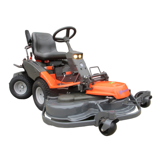
These instructions describe the Rider ProFlex 18. The power transmission from the engine is handled by a hydrostatic gearbox, which enables variable The Rider ProFlex 18 is equipped with a 18- speed by using the pedals. horsepower four-stroke V-twin Kawasaki engine. -
Page 11: Throttle Control
PRESENTATION Throttle control The throttle control regulates the engine speed, and thereby also the rotation speed of the blades. To increase or reduce the engine speed the control is moved forwards or backwards. Choke lever The choke lever is used for cold starting and to give the engine a richer fuel mixture. -
Page 12: Cutting Unit
PRESENTATION Cutting unit Examples of the accessories for Rider ProFlex: Rider ProFlex can be equipped with numerous attachments. • Brush The BioClip unit finely cuts the lawn by cutting the • Snow plough grass several times before returning the clippings to •... -
Page 13: Lever For Adjustment Of Cutting Height
PRESENTATION Lever for adjustment of the cutting height The cutting height can be adjusted to 7 different positions with the cutting height lever. To achieve an even cutting height it is important that the tyre pressures are the same on the front wheels (60 kPa). -
Page 14: Driving
DRIVING Before starting • Read the sections headed “Safety instructions” and “Presentation” before starting the mower. • Carry out daily maintenance before starting (see “Maintenance schedule” in the chapter on “Maintenance”). • Adjust the seat to the required position. Starting the engine 1. -
Page 15: Driving The Machine
DRIVING 5. When the engine starts release the ignition key immediately back to neutral position. IMPORTANT INFORMATION Do not run the starter for more than about 5 seconds at a time. If the engine does not start, wait about 15 seconds before trying again. - Page 16 DRIVING 3. Select the required cutting height (1–7) with the cutting height lever. 4. Push in the lock button on the lift lever and lower down the cutting unit. English –...
-
Page 17: Cutting Tips
DRIVING Cutting tips WARNING! Clear the lawn from stones and other objects which can be thrown out by the blades. • Localise and mark stones and other fixed objects to avoid collision. • Start with a high cutting height and reduce down until the required mowing results are obtained. -
Page 18: Stopping The Engine
DRIVING Stopping the engine Preferably allow the engine to idle for a minute to obtain normal working temperature before stopping it if it has been working hard. 1. Lift up the cutting unit by pulling the lever back to the locked position. 2. -
Page 19: Maintenance
MAINTENANCE Maintenance schedule The following is a list of the maintenance which should be conducted on the machine. For the items which are not described in these instructions go to an authorised service workshop. Maintenance interval in Maintenance Page Daily main- At least Weekly hours... - Page 20 MAINTENANCE Maintenance interval in Maintenance Page Daily main- At least Weekly hours tenance once a main- before after year tenance Lubricate throttle control Lubricate choke control Smörj styrkedja i ramtunnel. Lubricate steering chain inside frame tunnel Clean engine cooling air intake Clean the air filter pre-filter (oil-foam) Change engine oil Clean the air filter cartridge...
-
Page 21: Dismantling Of The Machine Hoods
MAINTENANCE Dismantling of the machine hoods Engine hood 1. Tip up the seat. 2. Turn the main catch on top of the engine hood 1/4 turn anti-clockwise. 3. Lift up the engine hood. If necessary the engine hood can be removed by taking out the hinge pins. -
Page 22: Checking The Engine's Cooling Air Intake
MAINTENANCE Left-hand fender Dismantle the screws (1 and 2), and lift off the fender. Transmission cover Undo the two screws (one on each side) and lift off the transmission cover. Check the engine’s cooling air intake Open the engine hood. Check that the cooling intake is free from leaves, grass and dirt. -
Page 23: Checking And Adjusting The Steering Wires
MAINTENANCE Checking and adjustment of the steering wires The steering is controlled by means of wires. These can in time become slack, which implies that the adjustment of the steering becomes altered. Check and adjust the steering as follows: 1. Dismantle the frame-plate by releasing the screws (two on each side). -
Page 24: Checking And Adjustment Of Throttle Wire
MAINTENANCE Checking and adjustment of the throttle wire Check that the engine responds to the throttle control and that the correct engine speed is achieved at full throttle. If in doubt, contact the service workshop If adjustment is necessary, adjust the lower wire as follows: 1. -
Page 25: Adjusting The Hydrostatic Wire
MAINTENANCE Adjusting the hydrostatic wire The hydrostatic wire (on the left) is adjusted as follows: 1. Remove the transmission cover. Unscrew the two screws (one on each side) and lift off the transmission cover. 2. Separate the lower ball joint, which is secured with a spring clip. -
Page 26: Adjusting The Brakes
MAINTENANCE Adjusting the brakes The parking brake (on the right) is adjusted as follows: 1. Remove the transmission cover. Unscrew the two screws (one on each side) and lift off the transmission cover. 2. Unhook the spring (A) from the screw (B). 3. -
Page 27: Replacement Of Air Filter
MAINTENANCE Replacing the air filter If the engine seems to lack power or does not run smoothly this may be because the air filter is clogged. It is therefore important to replace the air filter at regular intervals (see maintenance schedule on page 17-18 for correct service interval). -
Page 28: Replacement Of Fuel Filter
MAINTENANCE Replacement of the fuel filter Replace the fuel filter every 100 running hours (once per season) or more frequently if it is clogged. Replace the filter as follows: 1. Open the engine hood. 2. Move the hose clips away from the filter. Use a pair of flat pliers. -
Page 29: Checking The Battery Acid Level
MAINTENANCE Check the level of the battery acid Check that the level of the battery acid lies between the markings. Top up the cells with distilled water only . WARNING! Procedures on contact with acid External: Rinse well with plenty of water. Internal: Drink large quantities of water or milk. -
Page 30: Checking The Safety System
MAINTENANCE Inspecting the safety system The Rider is equipped with a safety system that prevents starting or driving under the following conditions: The engine should only be possible to start when the cutting unit is in its raised position and the hydrostat pedals are in the neutral position. -
Page 31: The Parts Of The Cutting Unit
MAINTENANCE The parts of the cutting unit A cutting unit with a rear ejector has been used in the instructions below, however, the same procedure applies to other units if not otherwise stated. The parts mentioned are: A. Catch E. Height setting arm B. - Page 32 MAINTENANCE 4. Slide in the unit so that the inner pins (B) bottom in the attachment frame’s groove. 5. Hook the rear end of the height adjustment arm (E) in place: Set the cutting height lever to the forward position. Release the pressure from the arm if necessary by lifting or pushin down on the front of the frame.
-
Page 33: Setting The Parallelism
MAINTENANCE Setting the parallelism and height for the cutting unit with rear ejector and BioClip unit The base unit is adjusted at the factory. When one of the attachments is fitted, the parallelism and height need to be adjusted. Starting point: 1. -
Page 34: Checking And Adjusting The Ground Pressure
MAINTENANCE Checking and adjustment of the cutting unit’s ground pressure To achieve the best cutting results the cutting unit should follow the underlying surface without pres- sing too hard against it. The pressure is adjusted with a screw on each side of the machine. -
Page 35: Service Position For The Cutting Unit
MAINTENANCE Service position for the cutting unit The cutting unit can be set in a service position to provide good access for cleaning, servicing and repair. The service position means that the unit is raised and locked in the vertical position. Placing in the service position 1. -
Page 36: Dismantling The Cutting Unit
MAINTENANCE Dismantling the cutting unit WARNING! Take care. Risk of crushing injury 1. Place the Rider on a level surface. 2. Apply the brakes by pressing down the pedal and lock using the pushbutton. 3. Lift up the unit using the lifting lever. 4. - Page 37 MAINTENANCE 9. Unhook the height adjustment arm (E) by raising the rear of the arm: Release the pressure from the arm if necessary by lifting or pushing down on the front of the frame. 10. Pull the handle (D) and the unit simultaneously. Release the handle when the unit has come out a bit.
-
Page 38: Removing The Attachment Frame
MAINTENANCE Removing the attachment frame Starting point for removing attachment frame: • Cutting unit must be removed. 1. Release the catch so that the front mounting can be lifted clear of the cutting unit. 2. Slide the attachment frame backwards so that the tongue on the cutting unit is clear of the slot in the attachment frame, then lift off the frame. -
Page 39: Assembling The Belts
MAINTENANCE Assembling the belt 1. Position the belt from the front and let the front end of the belt hang around the hook guard’s handle. 2. Fit the belt on the intermediate pulley and against the support wheel. 3. Fit the steering plate under the support wheel and tighten the bolts using two 13 mm socket spanners. -
Page 40: Changing The Cutting Unit's Belts
MAINTENANCE Replacing the cutting unit’s belts Belt replacement on BioClip 103 There are two versions of BioClip 103. Version 1 has a single toothed belt and version 2 has two belts. The toothed belts drive the blades and synchronise their rotation. The belts are located under a cover on top of the cutting unit. - Page 41 MAINTENANCE 6. Version 2: Assembly: First fit the lower belt and then the upper belt. Ensure the blades are positioned as set out in the diagram, at 90 degrees to each other, otherwise the belts must be adjusted. When the blade bearings are loose the belts can be moved around to the next tooth.
-
Page 42: Lubrication
LUBRICATION Lubrication chart English –... -
Page 43: General Lubrication
LUBRICATION General Remove the ignition key to prevent accidental movement during lubrication. If lubricating with an oil can, fill the can with engine oil. If lubricating with grease, use grease 503 98 96-01 or a similar chassis grease or bearing grease with good corrosion resistance, unless otherwise specified. - Page 44 LUBRICATION 2. Chains in frame tunnel Remove the cover from the frame tunnel, see step 1. Lubricate the chains in the frame tunnel using an oil can or motorcycle chain spray. Lubricate the shaft of the control wire pulleys with grease.
-
Page 45: Gear Lever
LUBRICATION Check the engine oil level when the Rider is on level ground. Raise the engine hood. Take out the dipstick, wipe it clean and push it in again. Do not screw in the dipstick. Take out the dipstick again and read the oil level. The oil level should be between the marks on the dipstick. - Page 46 LUBRICATION 6. Cutting unit Remove the nose cowling. Lubricate using an oil can: A. Safety catch Joints and bearings Lubricate with grease: B. Inner stud C. Slot for attachment frame 7. Triangular link Grease nipple located behind the right side front wheel.
-
Page 47: Parking Brake Wire
LUBRICATION 10. Oil filter, replacement 1. Open the engine hood. 2. Drain off the engine oil according to the work description “Changing of engine oil”. 3. Dismantle the oil filter. If necessary use a filter extractor. 4. Apply new, clean engine oil on the seal for the new filter. -
Page 48: Trouble Shooting Schedule
TROUBLE SHOOTING SCHEDULE Problem Procedure Engine will not start. • Fuel tank empty. • Plugs defective. • Plug connections defective. • Dirt in carburettor or fuel pipe. Starter does not pull round engine. • Battery flat. • Bad contact between cables and battery terminals. •... -
Page 49: Storage
STORAGE Winter storage At the end of the season the machine should To put the machine in order for storage follow these immediately be put in order for storage, also if it is instructions: going to stand idle for more than 30 days. Fuel 1. -
Page 50: Wiring Diagram
WIRING DIAGRAM Explanation of colour abbreviations in wiring diagram. 1. Microswitch, hydrostat 2. Microswitch, cutting unit RD = Red 3. Microswitch, seat BL = Blue 4. Ignition lock VT = White SV = Black 5. Counter GL = Yellow 6. Start relay GR = Grey 7. -
Page 51: Technical Data
TECHNICAL DATA Rider ProFlex 18 Dimensions Length, base machine 2 030 mm Width, base machine 900 mm Height 1 100 mm Kerb weight, base machine 334 kg Wheelbase 940 mm Track 720 mm Tyre size 18 x 7.50 x 8 Tyre pressure, front &... - Page 52 We, Husqvarna AB, S-561 82 Huskvarna, Sweden, tel. +46 36-146500, declare under sole responsibility that the rider mower Husqvarna Rider ProFlex from 1998’s serial numbers and onwards (the year is clearly stated in plain text on the type plate with subsequent serial number), is in conformity with the following standards or other normative documents following the provisions in the COUNCIL’S DIRECTIVES:...
-
Page 53: Servicejournal
SERVICEJOURNAL Work done Date, mileage, stamp, sign Pre-delivery service 1. Top up battery with acid and recharge for four hours. 2. Fit steering wheel, seat and any optional equipment. 3. Fit cutting unit. 4. Adjust cutting unit: Adjust lift springs (effective weight of cutting unit should be 12–15 kg, or set to maximum lift if brush is to be fitted). - Page 54 SERVICEJOURNAL Work done Date, mileage, stamp, sign 25 hour service 1. Clean the air filter pre-filter (oil-foam element). (more regularly in dusty conditions) 2. Clean the engine cooling air intake and transmission air intake. 3. Clean the fuel pump air filter. (in dusty conditions).
- Page 55 SERVICEJOURNAL Work done Date, mileage, stamp, sign 50 hour service 1. Clean / replace the air filter pre-filter (oil-foam element). (more regularly in dusty conditions) 2. Clean the engine cooling air intake and transmission air intake. 3. Clean the pre-filter air filter. 4.
- Page 56 SERVICEJOURNAL Work done Date, mileage, stamp, sign 100/200 hour service 1. Change the engine oil. Change the oil filter every 200 hours. 2. Clean / replace the air filter pre-filter (oil-foam element). 3. Clean the paper air filter. Replace every 200 hours. (more regularly in dusty conditions) 4.
- Page 57 SERVICEJOURNAL Work done Date, mileage, stamp, sign 300 hour service 1. Change engine oil. 2. Replace the air filter (oil-foam element). 3. Replace air filter ( paper air filter). Clean the fuel pump air filter. 5. Check/adjust cutting height setting. 6.
- Page 58 SERVICEJOURNAL Work done Date, mileage, stamp, sign At least once a season 1. Change engine oil (100 hours). 2. Clean / replace the air filter pre-filter (oil-foam element) (25 hours). (more regularly in dusty conditions) 3. Clean / replace the paper air filter (100 hours). (more regularly in dusty conditions).
- Page 59 SERVICEJOURNAL Date, mileage, stamp, sign Work done – English...
- Page 60 SERVICEJOURNAL Date, mileage, stamp, sign Work done English –...
- Page 61 SERVICEJOURNAL Date, mileage, stamp, sign Work done – English ´*3-T¶6"¨...
- Page 62 English –...
- Page 63 ´*3-T¶6"¨ 2001W05...