Table of Contents
Advertisement
Available languages
Available languages
Quick Links
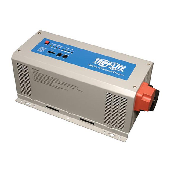
Sine Wave DC-to-AC Inverter/Chargers
Table of Contents
3. Battery Installation
and Maintenance
Owner's Manual
Models: APS1012SW, APS2012SW
12VDC to 120VAC
2
3
3
3
6
6
6
6
6
6
8
8
8
1111 W. 35th Street, Chicago, IL 60609 USA
www.tripplite.com/support
Copyright © 2011 Tripp Lite. All rights reserved.
7. Service and
1
10
10
10
11
11
12
12
13
Advertisement
Chapters
Table of Contents

Related Manuals for Tripp Lite APS1012SW


Summary of Contents for Tripp Lite APS1012SW
-
Page 1: Table Of Contents
2.2 Transfer Switching Speed Warranty Registration 3. Battery Installation Español and Maintenance 3.1 Select Battery Type 3.2 Monthly Maintenance 3.3 Battery Installation 3.4 Battery Connection 1111 W. 35th Street, Chicago, IL 60609 USA www.tripplite.com/support Copyright © 2011 Tripp Lite. All rights reserved. -
Page 2: Important Safety Instructions
SAVE THESE INSTRUCTIONS! This manual contains important instructions and warnings that should be followed during the installation, operation and storage of all Tripp Lite Inverter/Chargers. Location Warnings • Install your Inverter/Charger in a location or compartment that minimizes exposure to heat, dust, direct sunlight and moisture. -
Page 3: Overview & Features
1.1 Overview • Tripp Lite’s Sine Wave Inverter-Charger is a heavy-duty unit generating a pure sine wave from a 12V battery bank. It can supply energy to a wide range of connected equipment; from heaters, air conditioners, refrigerators and vacuum cleaners to computers and peripheral devices. - Page 4 1. Overview and Features LED and Alarm Indicator LED 1 LED 2 LED 3 LED 4 LED 5 LED 6 LED 7 LED 8 Alarm AC Normal 10.8V~11.5V 11.5 ~ 12.5V 12.5 ~ 13.5V >13.5V Flashing DC Mode 10.2 ~ 11.5V 11.5 ~ 12.5V 12.5 ~ 13.0V >13.0V 1 beep Battery Low 10.2 ~ 11.5V 11.5 ~ 12.5V 12.5 ~ 13.0V >13.0V...
- Page 5 1. Overview and Features 1.2.7 Battery Voltage (LED 5-8) LED 5-8 indicate the battery capacity as detailed in the following table: Battery Voltage LED 5 LED 6 LED 7 LED 8 — — — — — — 100% 1.2.8 Voltage Setting (Switch 1-3)* Switch DC-to-AC Transfer Delay (Switch 1) 30 sec (Default)
-
Page 6: Optional Features
These switches control the maximum charging rate in amps. The charge rate has 8 stages. It can be adjusted by setting these switches as shown in the following table: Switch 6 Switch 7 Switch 8 APS1012SW 20A (Default) APS2012SW 30A (Default) Note: The charging rate depends on the battery bank size. Consult the battery manufacturer’s specs for the maximum allowed charge rate (usually 0.3 times the AH rating). - Page 7 Select a battery or system of batteries that will provide your Inverter/Charger with proper DC voltage and an adequate amp- hour capacity to power your application. Even though Tripp Lite Inverter/Chargers are highly-efficient at DC-to-AC inversion, their rated output capacities are limited by the total amp-hour capacity of connected batteries and the support of your vehicle’s alternator if the engine is kept running.
-
Page 8: Monthly Maintenance
3. Battery 3.2 Monthly Maintenance • Check the level of the electrolyte of each Wet-Cell battery cell monthly after the batteries have been charged. It should be about one-half inch above the top of the plates, but not completely full. Note: This is not necessary on maintenance-free batteries. -
Page 9: Inverter/Charger
3. Battery • Connect Fuse: NEC (National Electrical Code) article 551 requires that you connect all of your Inverter/Charger’s positive DC Terminals directly to a UL-listed fuse(s) and fuse block(s) within 18 inches of the battery. The fuse’s rating must equal or exceed the minimum DC fuse rating displayed on the Inverter/Charger’s nameplate. -
Page 10: Installation And Operation
4. Installation and Operation 4.1 Installation 4.1.1 Environment The Inverter/Charger must be installed in a protected location that is isolated from sources of high temperature and moisture. To promote peak performance, battery cables should be kept as short as possible. However, do not install the Inverter/Charger in the same compartment as non-sealed batteries. -
Page 11: Installation And Start-Up
Press the ON/OFF button. The system will start working after a few seconds. If the AC source power fails, the unit will work in Inverter mode. Otherwise, the system will switch to AC Mode and will power the load while charging the battery. 5. Technical Specifications Model APS1012SW APS2012SW Specification Continuous Power... -
Page 12: Troubleshooting
If the system still does not start up properly, visit www.tripplite.com/support. 7. Service Your Tripp Lite product is covered by the warranty described in this manual. A variety of Extended Warranty and On-Site Service Programs are also available from Tripp Lite. For more information on service, visit www.tripplite.com/support. Before returning your product for service, follow these steps: 1. -
Page 13: Español
3.1 Seleccionar el tipo de batería 3.2 Mantenimiento mensual 3.3 Instalación de la batería 3.4 Conexión de la batería 1111 W. 35th Street, Chicago, IL 60609 USA www.tripplite.com/support Copyright © 2011 Tripp Lite. Todos los derechos reservados. -
Page 14: Instrucciones De Seguridad Importantes
¡GUARDE ESTAS INSTRUCCIONES! Este manual contiene instrucciones y advertencias importantes que se deben seguir durante la instalación, el funcionamiento y el almacenaje de todos los convertidores/cargadores Tripp Lite. Advertencias de ubicación • Instale su convertidor/cargador en una ubicación o compartimento que minimice la exposición al calor, polvo, luz solar directa y humedad. -
Page 15: Visión De Conjunto Y Características
1.1 Visión de conjunto • El convertidor/cargador de ondas sinusoidales de Tripp Lite es una unidad de carga de gran potencia que genera una onda sinusoidal pura a partir de un módulo de baterías de 12V. Puede suministrar energía a gran variedad de equipos conectados: desde radiadores, aparatos de aire acondicionado, refrigeradores y aspiradoras a ordenadores y dispositivos periféricos. - Page 16 1. Visión de conjunto y características LED e indicador de alarmas LED 1 LED 2 LED 3 LED 4 LED 5 LED 6 LED 7 LED 8 Alarma 10.8V~ 11.5 ~ 12.5 ~ CA Normal Off* >13.5V Apagado Flashing*** 11.5V 12.5V 13.5V 10.2 ~...
- Page 17 1. Visión de conjunto y características 1.2.7 Voltaje de la batería (LED 5-8) Los LED 5-8 indican la capacidad de la batería como se detalla en la siguiente tabla: Voltaje de la batería LED 5 LED 6 LED 7 LED 8 —...
-
Page 18: Características Opcionales
Interruptor 6 Interruptor 7 Interruptor 8 APS1012SW 20A (Predeterminado) APS2012SW 30A (Predeterminado) Nota 1: el régimen de carga depende del tamaño del módulo de baterías. Consulte las especificaciones del fabricante de la batería para la tasa de carga máxima permisible (normalmente 0.3 veces la especificación AH [Ampers Hours]). -
Page 19: De La Batería
Lite recomienda usar al menos dos baterías, si es posible alimentadas por un alternador de servicio pesado siempre que el vehículo esté funcionando. Los inversores/cargadores Tripp Lite proporcionarán energía adecuada para uso ordinario por tiempos limitados sin la ayuda de energía de la red o de un generador. -
Page 20: Mantenimiento Mensual
3. Batería 3.2 Mantenimiento mensual • Compruebe mensualmente el nivel del electrolito de cada batería de celda húmeda después que las baterías han sido cargadas. Debe estar 13 mm [1/2 media pulgada] aproximadamente sobre el borde superior de las placas, pero no completamente llena. - Page 21 3. Batería • Conectar el fusible: el artículo 551 del NEC (Código Eléctrico Nacional) exige que conecte todos los terminales CC positivos de su convertidor/cargador directamente a un fusible o fusibles homologados por UL y un bloque o bloques de fusibles que sean iguales o excedan el régimen mínimo de fusible CC que se muestra en la placa del convertidor/cargador.
-
Page 22: Instalación Y Funcionamiento
4. Instalación y funcionamiento 4.1 Instalación 4.1.1 Entorno El convertidor/cargador debe estar instalado en una ubicación protegida que esté aislada de fuentes de temperatura y humedad elevadas. Con el fin de fomentar el máximo rendimiento, los cables de la batería deben ser lo más cortos posible. No obstante, no se debe instalar el convertidor/cargador en el mismo compartimento que las baterías no selladas. -
Page 23: Instalación Y Puesta En Marcha
Pulse el botón ON/OFF. El sistema empezará a funcionar en pocos segundos. Si la fuente de energía CA fallase, la unidad funcionará en el modo convertidor. De otro modo, el sistema pasará al modo CA y suministrará potencia mientras carga la batería. 5. Especificaciones técnicas Modelo APS1012SW APS2012SW Especificación Potencia Continua 1000 vatios 2000 vatios Eficiencia Máxima del Inversor... -
Page 24: Solución De Problemas
La presente garantía no cubre ningún daño (directo, indirecto, especial o consecuencial) del producto que ocurra durante el envío a Tripp Lite o a un centro de servicio técnico de Tripp Lite autorizado. Los productos enviados a Tripp Lite o a un centro de servicio técnico de Tripp Lite autorizado deben tener prepagos los cargos de transporte.