
Related Manuals for UNI-T UT30B


Summary of Contents for UNI-T UT30B
-
Page 1: Table Of Contents
C. Rules for safe operation D. International Electrical Symbols E. General Specifications F. Specification G. Operation plate H. Make Measurements Fuse and battery replacement J. Accessories Remark: The model of UT30B,UT30C,UT30D will be marked as UT30BL,UT30CL UT30DL,if they have backlight function. -
Page 2: Introduction
Model UT30B/C/D/F: OPERATING MANUAL A. Introduction UT30 series Multimeter is 3 1/2 digits with steady operations,fashionable structure and highly reliable hand-held measuring instrument. The meter can measure DC/AC voltage, DC/AC current, Resistance, Frequency, Temperature, Diode, Transistor hFE, and Continuity. It is an ideal tool for... -
Page 3: Safety Information
Model UT30B/C/D/F: OPERATING MANUAL B. Safety Information This Meter complies with the standards IEC61010-1: in pollution degree 2, overvoltage category (CAT I 600V, CAT II 300V) and double insulation. CAT. I: Signal level, special equipment or parts of equipment, telecommunication, electronic, etc., with smaller transient overvoltages than overvoltages CAT. -
Page 4: Rules For Safe Operation
Model UT30B/C/D/F: OPERATING MANUAL Model UT30B/C/D/F: OPERATING MANUAL C.Rules for safe operation(1) Use the meter only as the rules specified in this manual, otherwise, the protection provided by the meter may be impaired. Do not operate the meter unless the bottom case has been closed as terminal can carry voltage. - Page 5 Model UT30B/C/D/F: OPERATING MANUAL C.Rules for safe operation(2) When measuring voltage higher than DC 60V or AC 30Vrms, pay extra attention to avoid electric shock. Make sure to replace right type and right rating fuse. Do not operate or store the Meter under high temperature or humid condition.
-
Page 6: International Electrical Symbols
Model UT30B/C/D/F: OPERATING MANUAL D.International Electrical Symbols Low Battery Earth Ground Warning Double Insulation AC current Diode DC current Buzzer AC or DC Fuse Conforms to Standards of European Union. -
Page 7: General Specifications
Model UT30B/C/D/F: OPERATING MANUAL E.General Specifications(1) 1. The maximum voltage, between any terminal and earth, is 600Vrms. A . The“COM”input terminal is always connected with the black test lead. B . The“V mA”input terminal is always connected with the red test lead and is used to measure voltage up to 500V,resistance and current up to 200mA. - Page 8 Model UT30B/C/D/F: OPERATING MANUAL E.General Specifications(2) 6. Temperature: Operating: 0 -104 Storing:-10 -122 7. Altitude: Operating:2000m Storage:10000m Relative humidity:Max.relative humidity 80% for temperature up to decreasing linearly to 50% relative humidity at 40 9. Battery: 9V NEDA 1604 or 6F22 or 006P.
-
Page 9: Specification
Model UT30B/C/D/F: OPERATING MANUAL F.Specification(1) Accuracy: (a% reading + b digit), which guarantee one year. Environmental Temperature:23 Relative Humidity: <75% 1. DC Voltage Accuracy Range Resolution UT30B UT30C UT30D UT30F 200mV 100 V (0.5%+2) 2000mV(2V) 10mV 200V 100mV (0.8%+2) 500V Input Impedance:10M for all the ranges. - Page 10 100mV (1.2%+10) 500V (1.2%+3) Input Impedance: (approx. 5M ) of UT30B\C\D, but all ranges of UT30F are 10M . Frequency: 40-400Hz Display: RMS of Sine Wave Value (Average Value) Overload protection: At 200mV range, it is protected at 230V(AC / DC...
- Page 11 Model UT30B/C/D/F: OPERATING MANUAL F.Specification(3) 3. DC Current Accuracy Range Resolution UT30B UT30C UT30D UT30F 200 A 100nA 2000 A(2mA) (1%+2) 20mA 10 A 200mA 100 A (1.2%+2) 10mA (2%+5) Overload Protection:315mA/250V fuse, No fuse at 10A,measuring time limit is equal to or less than 10 seconds, and time interval should be equal to or over 15 minutes.
- Page 12 Model UT30B/C/D/F: OPERATING MANUAL F.Specification(4) 4. AC Current(Only UT30F) Accuracy Range Resolution (1.8%+3) 100 A 200mA (3%+7) 10mA Overload Protection: 315mA/250V fuse, No fuse at 10A,measuring time limit is equal to or less than 10 seconds; time interval is equal to or over 15 minutes.
- Page 13 Model UT30B/C/D/F: OPERATING MANUAL F.Specification(5) 5. Resistance Accuracy Range Resolution UT30B UT30C UT30D UT30F (0.8%+5) 2000 (2k ) (0.8%+2) 200k (1%+5) Overload Protection: All ranges are 230V(DC/ AC current).
- Page 14 Model UT30B/C/D/F: OPERATING MANUAL...
- Page 15 Model UT30B/C/D/F: OPERATING MANUAL F.Specification(7) 7. Frequency(Only UT30F Auto Range) Range Resolution Accuracy (0.1%+3) 2kHz 10MHz 1Hz 10kHz 8. Square Wave Output(Only UT30D) Range Illustration Output approx. at 50Hz Square Wave .As a simple signal source , with 100k resistance output.
- Page 16 Model UT30B/C/D/F: OPERATING MANUAL F.Specification(8) No overload protection for this range; make sure voltage output of calibrated equipment is less than 10V to avoid damages to the Meter. 9. Diode, Transistor, Continuity Beeper Test Function Range Resolution 30B 30C 30D 30F...
-
Page 17: Operation Plate
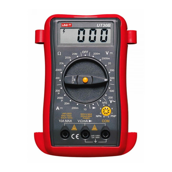
Model UT30B/C/D/F: OPERATING MANUAL G.Operation Plate Overload Protection: 230V(DC/ AC current),Only Operation Plate(see figure 1) 1. Liquid Crystal Display 2. Data hold or backlight selection button except UT30F(AC/ DC exchange)* 3. Rotary Switch 4. Transistor Test Jack 5. Common Input Jack ( figure 1) 6. -
Page 18: Make Measurements
Model UT30B/C/D/F: OPERATING MANUAL H.Make Measurements(1) First, set rotary switch to proper position. When the battery is low,“ ”will appear on LCD. Second, the “ ” symbol beside the input jack warns you when testing current and voltage. Input values must not exceed the limit. - Page 19 Model UT30B/C/D/F: OPERATING MANUAL Model UT30B/C/D/F: OPERATING MANUAL H.Make Measurements(2) 1) Never measure voltage value exceeding 500V, although it is possible to get the reading. This may cause damages to the internal circuit and danger to users; 2) Set rotary switch to maximum range, if the voltage value to be tested is unknown.
- Page 20 Model UT30B/C/D/F: OPERATING MANUAL H.Make Measurements(3) 2. AC Voltage Measurement (see figure 3) black red (figure 3) Same as DC voltage measurement.
- Page 21 Model UT30B/C/D/F: OPERATING MANUAL H.Make Measurements(4) 3. DC Current Measurement(see figure 4) black red (figure 4) 1) Do not measure when value between open voltage and earth is exceeding safety voltage 60V because it may cause damages to the measuring object or instrument and also hurt the user.
- Page 22 Model UT30B/C/D/F: OPERATING MANUAL H.Make Measurements(5) 2) Before measurement, cut off the power to the object to be measured and inspect if input terminal or rotary switch is set to the right range then you can measure the object with power on.
- Page 23 Model UT30B/C/D/F: OPERATING MANUAL H.Make Measurements(6) 4. AC Current Measurement(Only for UT30F)(see figure 5) black red (figure 5) Same as DC current measurement...
- Page 24 Model UT30B/C/D/F: OPERATING MANUAL H.Make Measurements(7) 5. Resistance Measurement (see figure 6) 1) To avoid damages to the Meter when measuring resistance, cut off the power of the object and make sure there is no charge in capacitor. 2) Test lead wires take 0.1 -0.3 tolerance when measuring resistance.
- Page 25 Model UT30B/C/D/F: OPERATING MANUAL H.Make Measurements(8) 6. Diode measurement (see figure 7) Avoid damages to the meter. When measuring diode, cut off the power supply of the object and make sure there is no charge in capacitor. When measuring voltage drop of diode,...
- Page 26 Model UT30B/C/D/F: OPERATING MANUAL H.Make Measurements(9) 7. Transistor hFE Measurement (see figure 8) 1) Check that the transistor is PNP or NPN type. 2) Connect the transistor to be measured to the corresponding jacks. 3) LCD display hFE reference value.
- Page 27 Model UT30B/C/D/F: OPERATING MANUAL H.Make Measurements(10) 8. Temperature Measurement:(Only for UT30C)(see figure 9) 1) Insert the black K type thermocouple (P/N:41700103) into “COM” socket. Red lead of temp. probe into “ ” socket, LCD displays the measuring value with unit in 2) The temperature probe limits to below .
- Page 28 Model UT30B/C/D/F: OPERATING MANUAL H.Make Measurements(11) 9. Square Wave Output:(Only UT30D) (see figure 10) 1) To avoid damages to the meter, do not let output terminal reach higher then 10V voltage. 2) The frequency is 50Hz. 3) The output voltage range will be over 3V when it is loaded 1M .
- Page 29 Model UT30B/C/D/F: OPERATING MANUAL H.Make Measurements(12) 10. Frequency Measurement (Only for UT30F)(see figure 11) 1) Do not input voltage over 230V RMS to avoid damages to the meter. 2) The LCD will display reading when the measured frequency is more than 10V, but the read out may exceed specification.
-
Page 30: Fuse And Battery Replacement
Model UT30B/C/D/F: OPERATING MANUAL I.Fuse and battery replacement H. Fuse and battery replacement(see figure 12) 1) Turn the rotary switch to OFF position,and remove the test leads from terminals. 2) Remove two rubber feet and two screws from the bottom case. -
Page 31: Accessories
Model UT30B/C/D/F: OPERATING MANUAL J.Accessories 1) Operating manual 2) Test leads 3) Thermocouple(Only for UT30C) ** END ** This operating manual is subject to change without notice. - Page 32 Model UT30B/C/D/F: OPERATING MANUAL Copyright 2001 Uni-Trend International Limited. All rights reserved. Manufacturer: UNI-TREND TECHNOLOGY(DONG GUAN)LIMITED Address: Dong Fang Da Dao, Bei Shan Dong Fang Industrial Development District, Hu Men Town, Dong Guan City, Guang Dong Province, China Headquarters: Uni-Trend International Limited...