
Related Manuals for Gravely 915015 - 1742 ZT, 9150156 - 2048 ZT


Summary of Contents for Gravely 915015 - 1742 ZT, 9150156 - 2048 ZT
- Page 1 ZT Zero Turn Mower Owner/Operator Manual Models 915015 - 1742 ZT 915016 - 2048 ZT ENGLISH FRANÇAIS ESPAÑOL 01562700A 8/00 Supersedes 01562700 Printed in USA...
-
Page 3: Controls And Features
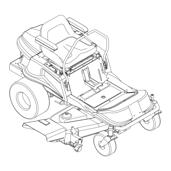
WARNING The engine exhaust from this product contains chemicals known to the State of California to cause cancer, birth defects or other reproductive harm. CONTROLS AND FEATURES OL4030 ENGLISH 1. Steering Control Levers 2. Battery Compartment 3. Ignition Switch 4. Power Take Off (PTO) Switch 5. - Page 4 ESPAÑOL 1. Palancas de control de dirección 2. Compartimento de la batería 3. Interruptor de encendido 4. Interruptor de la toma de fuerza (TDF) 5. Control del acelerador (2048) Control del acelerador/ estrangulador (1742) 6. Control del estrangulador (2048) 7. Palanca del freno de estacionamiento 8.
-
Page 5: Table Of Contents
Gravely authorized replacement part may adversely affect the performance, durability, or safety of this unit and may void the warranty. Gravely disclaims liability for any claims or damages, whether warranty, property damage, personal injury or death arising out of the use of unauthorized replacement parts. -
Page 6: Safety
SAFETY ALERTS Look for these symbols to point out important safety precautions. They mean: Attention! Personal Safety Is Involved! Become Alert! Obey The Message! The safety alert symbol is used in decals on the unit and with proper operation procedures in this manual. Understand the safety message. -
Page 7: Safety Rules
Never carry children, even if mower is disengaged. OL4110 OL4120 Remove objects that could be thrown by the blade. OL0910 Go up and down slopes, not across. Do not operate on slopes that exceed 10°. OL4130 • If machine stops going uphill, stop blade and back down slowly. - Page 8 Only allow responsible adults who are trained and familiar with the instructions to operate the machine. Training includes actual operation. Clear the area of objects such as tree branches, rocks, toys, wire, etc., which could be picked up and thrown by the blades.
- Page 9 Keep children out of the mowing area and under the watchful care of another responsible adult. Be alert and turn off machine if children enter the area. Before and when backing up, look behind and down for small children. Never carry children, even if mower is disengaged. They may fall off and be seriously injured or interfere with safe machine operation.
-
Page 10: Assembly
To ensure safe and proper operation, all parts and hardware must be tightened securely. Use the correct tools to ensure proper tightness. TO REMOVE TRACTOR FROM SKID 1. Remove all accessible loose parts from shipping carton. 2. Remove top and sides of crate. 3. -
Page 11: Operation
"NEUTRAL LOCK" position, or while the PTO Switch is in the "ON" position. Do not operate tractor unless operator presence system functions as described. Contact your Gravely Dealer for repair. Ignition Switch The ignition switch is operated with a removable key. - Page 12 Neutral Lock To start, lock unit in neutral by pushing both Travel-Steering Control Levers outward – to each side – from centered (neutral) position. Neutral Lock Position Straight Forward Push the Travel-Steering Control Levers SLOWLY forward the same distance from the centered (neutral) position.
- Page 13 Attachment Lift Lever Lock WARNING: AVOID injury from stored energy in lift assist spring. DO NOT unlock attachment lift lever with mower deck removed. ALWAYS engage Attachment Lift Lever Lock when removing mower deck. See Service and Adjustments . ALWAYS engage the attachment Lift Lever Lock when removing or servicing the mower deck.
-
Page 14: Starting The Engine
STARTING THE ENGINE NOTE: Before starting, read warm and cold starting procedures below. 1. The operator must be seated. 2. Travel-Steering Control levers must be in the "NEUTRAL-LOCK" position. 3. The PTO Switch must be in the "OFF" position. 4. For 2048 - If the engine is cold, apply choke. For 1742 - Place Throttle/Choke control in Choke position. - Page 15 TO OPERATE ON HILLS CAUTION: Do not drive up or down hills with slopes greater than 10˚ and do not drive across any slope. • Use a slow speed before starting up or down hills. • Avoid stopping or changing speed on hills. •...
- Page 16 MULCHING OPERATION (OPTIONAL) The special mulching blades and baffles will allow the grass clippings to be cut many times to reduce their size. As the grass falls onto the lawn,it disperses into the grass and will not be noticed. Also, the mulched grass biodegrades quickly and provides nutrients for the lawn.
-
Page 17: Maintenance
MAINTENANCE SCHEDULE Check Operator Presence Systems Check for Loose Fasteners Check Parking Brake Interlock Check Parking Brake Check Tires Check Blades Check Battery Clean Battery Check Belts Clean Transaxle Lubrication Cleaning Check Engine Oil Level Change Engine Oil and Filter Check Air Filter Service Precleaner Replace Paper Element... - Page 18 Do not operate tractor unless operator presence system functions as described. Contact your Gravely dealer for repair. CHECK FOR LOOSE FASTENERS Be certain that all hardware is tightened to the proper torque.
-
Page 19: Check Battery
4. Slide blade onto an unthreaded portion of the steel bolt or pin and hold the bolt or pin parallel with the ground. If blade is balanced, it should remain in a horizontal position. If either end of the blade moves downward, sharpen the heavy end until the blade is balanced. - Page 20 5. Remove wing nut from the Battery Rod and remove the rod. 6. Disconnect the negative (–) cable first. 7. Disconnect the positive cable (+) second. 8. Lift the battery out of the unit and place battery on a bench or other well ventilated area where an acid spill will not create damage.
-
Page 21: Replace Spark Plugs
ENGINE To access engine: 1. Unhook Engine Cover latch. 2. Lift rear of cover and slide out. Set cover aside. 3. To replace cover: Slide front of cover into slot. 4. Insert the back edge of cover into its support bracket. -
Page 22: To Remove/Install 48" & 42" Mower Deck
CAUTION: Before performing any service or adjustments: • Turn PTO switch "OFF". • Park mower on a hard, flat, level surface. • Place steering control levers in neutral lock (fully outward) position. • Set parking brake. • Turn ignition switch "OFF" and remove key. •... - Page 23 WARNING: AVOID injury from stored energy in lift assist spring. DO NOT unlock attachment lift lever with mower deck removed. ALWAYS engage Attachment Lift Lever Lock when removing mower deck. See Operation. 3. Engage Attachment Lift Lock. Pull handle out and rotate down 90°.
-
Page 24: To Level Mower
6. Tighten height adjuster nuts. 7. Secure height adjusters with washers and hair pins. To Adjust 42" Deck: 1. Place mower in the number three (3) postition. 2. Place anti-scalp rollers in highest position so they do not touch the ground during adjustment. 3. -
Page 25: Clutch Deck Belt Replacement (48"/42")
BELTS WARNING: MOVING PARTS can cut or amputate body parts. ALWAYS wait for moving parts to stop before unit maintenance or service. Clutch to Deck Belt Replacement (48" Deck) 1. Disconnect main idler spring from bolt under frame. 2. Remove belt from electric clutch and drive pulley. 3. -
Page 26: Transaxle Belt Replacement
4. Remove the lock nut, washer, spring, and spacer from the eye-bolt. Discard the lock nut and inner spacer. 5. Loosen the nut on the belt adjustment bracket. 6. Rotate belt adjustment arm out of the way, and remove mower deck belt. 7. -
Page 27: Adjusting The Unit To Track Straight
Clutch Shaft Belt Replacement 1. Remove transaxle belt (see procedure above). 2. Remove clutch shaft idler spring from frame. 3. Remove clutch shaft belt from engine sheave. 4. Remove clutch shaft belt from clutch sheave. 1. Transaxle Belt 4. Engine Sheave 2. -
Page 28: Seat Adjustment
OE0740 poorly, stop running, or prevent it from starting. Check wiring. See "ELECTRICAL SCHEMATIC" in the Parts Manual . Contact your Gravely Dealer. TO REPLACE FUSE Replace with 30 amp automotive-type plug-in fuse. The fuse holder is located under seat support near right rear tire. -
Page 29: Storage
CAUTION: Never cover tractor while engine and exhaust areas are still warm. See the Engine Manual for detailed instructions on storage. SERVICE PARTS Be sure to always use genuine Gravely parts to keep your unit running like new. Part no. 03123700 01584500... -
Page 30: Troubleshooting
9. Drain fuel tank and carburetor, refill tank with fresh gasoline and replace fuel filter. 10. Check all wiring. 11. Contact your Gravely Dealer. 12. Recharge or replace battery. 13. Replace fuse. 14. Clean battery terminals. 15. Contact your Gravely Dealer. -
Page 31: Specifications
1. Improper air pressure in tires. track straight 2. Eccentrics out of alignment. CORRECTION 1. Contact your Gravely Dealer. 1. Move throttle control to “SLOW” position and allow to idle for 30 seconds before stopping engine. 1. Replace blade(s). Tighten blade bolt. -
Page 32: Specifications
SPECIFICATIONS Model Number Description Engine Manufacturer Engine Model Number Engine Power - HP (KW) Engine Operating Fast Idle Speed - RPM Engine Displacement - cu. in. (cc) Fuel Fuel Tank Capacity - gal (Liters) Crankcase Capacity - qt (Liters) Length - in (cm) Width - in (cm) Height - in (cm) Weight - lbs (Kg) -
Page 33: Warranty
Gravely will be free from defects in material and workmanship for a period of two (2) years after the date of purchase. Gravely will repair any defect in material or workmansip, and repair or replace any defective part, subject to the exceptions, exclusions, conditions and limitations set forth herein. - Page 34 GRAVELY A Division of Ariens Company 655 West Ryan Street P.O. Box 157 Brillion, WI 54110-0157 920-756-2141 Fax 920-756-2407 www.gravely.com...