Table of Contents
Advertisement
Quick Links
SLP 05
Pure Balanced Vacuum Tube Preamplifier
Owner's Manual
NOTE: Before installing your new component, please read this manual carefully as it will inform you of the
specifications, proper installation and operation procedures. Also included in this manual are guidelines on how to
service and care for your new Cary Audio Design product.
Advertisement
Table of Contents

Related Manuals for Cary Audio Design SLP 05


Summary of Contents for Cary Audio Design SLP 05
- Page 1 NOTE: Before installing your new component, please read this manual carefully as it will inform you of the specifications, proper installation and operation procedures. Also included in this manual are guidelines on how to service and care for your new Cary Audio Design product.
-
Page 2: Table Of Contents
CONTENTS _________________________________________________________ Welcome..........................3 Introduction........................4-5 Specifications ........................6-7 Features........................... 7-12 Installation ..........................12 Operation ..........................13 Service and Care .......................14 Warranty ........................15-16... -
Page 3: Welcome
I would like to personally thank you for your decision to invest in the new Cary Audio Design SLP 05 preamplifier. The SLP 05 is a continuance and elevation of the SLP series of preamplifiers originating in 1990. The SLP series has been in continuous production for over 15 years and provides musical enjoyment across the world. -
Page 4: Introduction
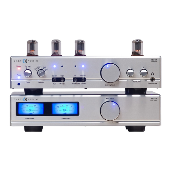
The cinema bypass circuitry may be engaged by toggling the Cinema bypass switch on the front panel of the preamplifier. If the SLP 05 power switch is turned to the off position, the SLP 05 automatically defaults to the cinema bypass mode. - Page 5 SLP 05 in operation. The two meters on the front of the power supply indicate the B+ plate voltage (210 VDC) along with the plate current (60 ma.). You will always know at a glance if all is OK with the operating conditions.
-
Page 6: Specifications
SPECIFICATIONS ___________________________________________________ This section describes the basic specifications of the SLP 05 vacuum tube preamplifier at the time of printing. Specifications are subject to change without notice or obligation. When the following cautionary terms are used in this manual, these definitions apply:... -
Page 7: Features
The matching ‘chassis size’ external power supply comes with 5AR4 vacuum tube voltage rectification and has two front panel meters for the circuit voltage and the current bias readings. The SLP 05 has a timer warm up circuit that allows safe use with ‘rapid turn on’ solid state power amplifiers, like the CAD 500 MB mono 500 watts per channel power amplifiers. - Page 8 3:00 o’clock or even all the way up. This does not stress the SLP 05 in any fashion. The SLP 05 is a Class A operating circuit and in reality is running at full potential at all times.
- Page 9 Back Panel – Preamplifier Special Note: The balanced input and output XLR connectors follow the ITT Cannon pin out configuration. This pin out calls for the shield to be wired to pin #1. The normal-phase (hot) is wired to pin #2. Pin #3 is the inverted phase.
- Page 10 Tube Placement Chart – Preamplifier 1. 6SN7 tube – left channel positive phase gain – buffer 2. 6SN7 tube – right channel positive phase gain – buffer 3. 6SN7 tube – left channel balanced input buffer 4. 6SN7 tube – left channel negative phase gain – buffer 5.
- Page 11 Power Supply Meter Bulb Replacement Guide The lamps (bulbs) that back light the voltage and current meters in the SLP 05 power supply may require service from time to time. These lamps are incandescent filament bulbs. The type of lamp is specified as Festoon Lamp with a 12 volt 1.2 watt rating.
-
Page 12: Installation
If you were the original purchaser of this unit and you purchased it in the United States, you should fill out the enclosed warranty registration card and return it to Cary Audio Design within 15 days of your purchase. Cary Audio Design also suggests that you keep your original packing cartons in case you ever need to ship the unit when moving to a new home. -
Page 13: Operation
SLP 05 in operation. The two meters on the front of the power supply indicate the B+ plate voltage (210 VDC) along with the plate current (60 ma.). You will always know at a glance if all is OK with the operating conditions. -
Page 14: Service And Care
Non-Warranty Repairs Cary Audio Design will provide repair service for its products charging on a time and expense basis. At this time, the standard non warranty service bench fee is $125 with all parts used for repair charged extra. This may change with time and is not a quote for service. -
Page 15: Warranty
UNITED STATES LIMITED WARRANTY ______________________________ Cary Audio Design warrants to the original United States purchaser for use in the United States, that Cary Audio Design vacuum tube or solid state power amplifiers, surround sound processors or preamplifiers shall be free from defects in parts or workmanship for three (3) years from the date of the original purchase. -
Page 16: Warranty
Cary Audio Design. Under no circumstances is Cary Audio Design liable for incidental or consequential damages. Any implied warranties imposed by law terminate one (1) year from the date of purchase. - Page 17 1020 Goodworth Drive Apex, North Carolina 27539 Tel: 919-355-0010 Fax: 919-355-0013 www.caryaudio.com...