Table of Contents
Advertisement
Available languages
Available languages
Quick Links
OWNER'S MANUAL
MANUAL DE USUARIO
NOTICE D'UTILISATION
Model No.
Modelo No.
Modèle n
LBD48D
CAUTION:
Read Rules for
Safe Operation
and Instructions
PRECAUCIÓN:
Lea Cuidadosamente las
Reglas e Instrucciones
de Seguridad
ATTENTION:
Lire et suivre attentivement
les instructions et
consignes de sécurité
de cette notice.
PRINTED IN U.S.A.
™
o
• Safety
• Assembly
Carefully
• Operation
• Maintenance
• Parts
the fastest way to purchase parts www.speedepart.com
48" SNOW BLADE
CUCHILLA QUITANIEVE DE 48" (122 CM)
LAME CHASSE-NEIGE DE 48 PO. (122 CM)
• Seguridad
• Armado
• Operación
• Mantenimiento
• Piezas
• Sécurité
• Assemblage
• Utilisation
• Entretien
• Pièces de Rechange
FORM NO. 42363 (10/13/11)
Advertisement
Chapters
Table of Contents

Related Manuals for Agri-Fab LBD48D


Summary of Contents for Agri-Fab LBD48D
- Page 1 ™ OWNER'S MANUAL MANUAL DE USUARIO NOTICE D’UTILISATION Model No. Modelo No. Modèle n LBD48D 48" SNOW BLADE CUCHILLA QUITANIEVE DE 48" (122 CM) CAUTION: LAME CHASSE-NEIGE DE 48 PO. (122 CM) Read Rules for Safe Operation • Safety and Instructions • Assembly Carefully • Operation...
-
Page 2: Table Of Contents
ENGLISH TABLE OF CONTENTS SAFETY RULES ............. 2 SERVICE AND ADJUSTMENTS ........13 CARTON CONTENTS ............ 2 STORAGE ..............13 FULL SIZE HARDWARE CHART ........3 TROUBLESHOOTING ..........13 ASSEMBLY ..............4 REPAIR PARTS ILLUSTRATION ......... 30 OPERATION ..............11 REPAIR PARTS LIST ............ 31 MAINTENANCE ............12 PARTS ORDERING/SERVICE ....BACK COVER RULES FOR SAFE OPERATION Any power equipment can cause injury if operated improperly or if the user does not understand how to operate the equipment. -
Page 3: Full Size Hardware Chart
ENGLISH SHOWN FULL SIZE NOT SHOWN FULL SIZE HARDWARE PACKAGE REF. QTY. DESCRIPTION REF. QTY. DESCRIPTION Cotter Pin 1/8" x 1-1/4" Hex Bolt, 1/4-20 x 3-1/4" LG. P Palnut, 3/8" Hex Bolt 1/4-20 x 1-1/4" Hex Bolt, 5/16-18 x 1" Q Hex Bolt, 3/8-16 x 1" Hex Bolt, 5/16-18 x 1-1/2" R Lockwasher, 3/8" Carriage Bolt 3/8-16 x 1-1/4" S Washer 1/2" Carriage Bolt, 3/8-16 x 1" T Spacer, 9/16" OD x 5/8" LG. U Spacer, 9/16" OD x 1" LG. Nylon Lock Nut, 1/4-20 Thread Nylon Lock Nut, 5/16-18 Thread V Cable End Fitting W Cable Mount Bracket Nylon Lock Nut, 3/8-16 Thread Hex Jam Nut, 5/16-24 Thread... -
Page 4: Assembly
ENGLISH ASSEMBLY SKIP TO STEP 2 IF YOUR TRACTOR HAS TWO TOOLS REQUIRED FOR ASSEMBLY FRONT BRACKETS FOR ATTACHING THE (1) Pliers MOWER DECK. (1) Hammer (1) Adjustable Wrench (or socket set) USE THE INSTRUCTIONS IN STEP 1 IF YOUR (1) 9/16" Open End or Box End Wrench TRACTOR HAS A SINGLE FRONT BRACKET (2) 7/16" Open End or Box End Wrench (2) -
Page 5: Long Hanger Bracket
STEP 2: USE THESE INSTRUCTIONS FOR ALL (SEE FIGURE 2) • Measure the distances L, H and W. TRACTORS L = distance from center of lower holes in frame bracket to front of tractor frame. STEP 4: (SEE FIGURE 4) H = distance to center of hole in frame bracket that is Refer to page 6 for examples of how to attach the Hanger closest to being 6" above ground level. Brackets to some other tractor models. W = distance between the inside of the frame brackets. • Select the pair of slots in the top of the Thrust Channel • Proceed to step 4. that will provide enough clearance between the blade and the front of the tractor while minimizing overhang. JOHN DEERE LT TRACTOR Select the pair of slots based on distance "L" measured in step 2 or step 3. L = 5" or less Attach to the front pair of slots. L = 5" to 7"... - Page 6 SEARS TRACTORS WITH JOHN DEERE LT CENTER SUSPENSION BRACKET 3/8" x 1" CARRIAGE 13" 12.75" BOLT 5/16" x 1" HEX BOLT 3/8" x 1" HEX BOLT FRAME BRACKET FRAME BRACKET LOCATE HANGER BRACKETS IN LOCATE HANGER BRACKETS IN FRONT MIDDLE SET OF SLOTS IN THRUST CHANNEL SET OF SLOTS IN THRUST CHANNEL MURRAY TRACTORS SEARS LAWN...
-
Page 7: Rear Mounting Bracket
ENGLISH STEP 5: STEP 8: (SEE FIGURE 5) (SEE FIGURE 8) • Attach the Rear Locating Bracket to the top of the Rear • Place the T hrust Channel between the two Rear Support Mounting Bracket using two 3/8" x 1" Carriage bolts and Channels. Install four 3/8" x 1" carriage bolts and 3/8" 3/8" nylock nuts. Tighten nuts. nylock nuts using the most widely spaced holes that align with slots. Finger tighten only. • Attach the Rear Support Channels to the middle set of holes in the sides of the Rear Mounting Bracket using • If the Rear Support Channels bump against the bottom four 3/8" x 1" Carriage Bolts and 3/8" nylock nuts. Finger of the tractor, reattach the rear of the channels to a lower tighten only. set of holes in the Rear Mounting Bracket. If there is more clearance than necessary between the Rear Support REAR LOCATING... -
Page 8: Channel Assembly
ENGLISH STEP 10: STEP 12: (SEE FIGURE 10) (SEE FIGURE 12) • Place the two angle lock bars together so that all holes • Assemble a 3/8" x 1-1/4" carriage bolt through the square are aligned. Assemble a 3/8" x 1-1/4" carriage bolt and hole in the cable mount bracket and through the square a 3/8" nylock nut in the top hole. Be sure to insert the hole in the angle lock bars as shown. (The carriage bolts bolt from the side indicated. Finger tighten only. should face in opposite directions.) Using pliers hold the • Insert the round hook end of the angle lock spring up cable mount bracket in position, angling down towards through the hole in bracket (a). the L.H. hole in the channel as shown. Secure with a 3/8" nylock nut. Tighten. Refer also to figure 14 for the • Hold the angle lock bars so that the square holes are at the top. Insert the straight hook end of the angle lock correct angle for the cable mount bracket. spring through the middle hole in both angle lock bars. • Insert the angle lock bars down through the slot in the 3/8" x 1-1/4" channel. Underneath the channel, place a 1" long spacer CARRIAGE BOLT (E) on each side of the angle lock bars and insert a 1/4"... - Page 9 ENGLISH STEP 14: (SEE FIGURE 14) 1/8" x 1-1/4" PLASTIC • Assemble ball end of control cable up through hole in COTTER cable end fitting and pull until ball slips inside curled PIN (O) 3/8" HEX NUT edge of fitting as shown. If ball won't slip under edge of (TOP) curl it will need to be inserted through open end of curl. • Assemble a 1/4" x 1-1/4" hex bolt down through the cable BLADE end fitting, the 5/8" long spacer and the left hand hole 3/8" HEX NUT PIVOT in the channel assembly. Secure with a 1/4" nylock nut. (BOTTOM) SHAFT Tighten.
-
Page 10: Blade Pivot Rod
ENGLISH STEP 17: STEP 19: (SEE FIGURE 17) (SEE FIGURE 19) • From the left side, insert the welded end of the lift handle • Assemble the plastic grip onto the grip assembly. rod through the exposed holes in the end of the channel • Attach the grip assembly to the lift handle tube using assembly. Next, insert the lift link pin through the hole one 5/16" x 1-1/2" hex bolt and one 5/16" nylock nut. in the bracket that is welded to the lift handle rod. (The Do not overtighten the nylock nut. The grip assembly lift link is pre-assembled to the pivot support bracket). must pivot freely. Secure the bracket with a small hairpin cotter. • Assemble the ball end of the cable to a cable end fitting • Apply a light coating of oil to the straight upper portion as was done to the other end of the cable. Secure the of the lift handle rod. Slide the lift handle tube onto the cable end fitting to the weld bolt on the lock release grip rod. with a 1/4" nylock nut. Do not overtighten the nylock nut. The cable fitting must pivot freely. -
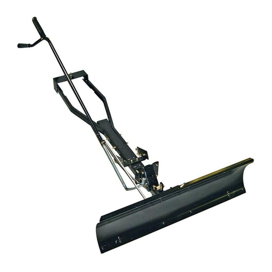
Page 11: Operation
OPERATION KNOW YOUR SNOW BLADE Read this owner's manual and safety rules before operating your snow blade. Compare the illustration below with your snow blade to familiarize yourself with the various controls and their locations. LOCK RELEASE GRIP ASSEMBLY LIFT HANDLE TUBE BLADE PIVOT ROD ANGLE LOCK BARS BLADE ADJUST SPRING LIFT HANDLE ROD BLADE SHOE CONTROL CABLE BLADE PIVOT SHAFT LOCK RELEASE GRIP ASS'Y. -
Page 12: Maintenance
Wheel weights and tire chains must be used with CAUTION: Inspect carefully the area your snow blade for traction. These accessories are to be worked before operating the snow available at your nearest Sears retail store. blade. Avoid pipes, roots, curbs or other heavy obstructions. Using the Snow Blade • Prepare the lawn tractor engine for cold weather using instructions furnished with the lawn tractor. • Always begin with the transmission in first (low) gear CAUTION: Know the terrain. Avoid and gradually increase speed as required. -
Page 13: Service And Adjustments
SERVICE AND ADJUSTMENTS To Adjust Blade Spring To Adjust the Blade Pivot Lock Mechanism • The tension of the blade adjust spring may be altered to • If the blade will not unlock and pivot, the angle lock bars permit the blade to tilt forward to bypass solid obstructions. are not disengaging from the slots in the pivot plate. To To change the spring tension, adjust the nuts at upper correct, adjust the 5/16" hex jam nuts to draw the end of end of the spring bolt. Turn the nuts counterclockwise to the control cable back towards the cable mount bracket. relieve tension and clockwise to increase tension. Refer The less the threaded end of the cable extends through to figure 15 on page 9. the bracket, the more the angle lock bars can retract to disengage from the slots in the pivot plate. See figure To Adjust Blade Shoes • The blade shoes at the ends of blade may be raised for CABLE MOUNT BRACKET close work on smooth surfaces or lowered to raise the blade to work on rough or uneven areas. Make sure both CONTROL shoes are set evenly and that the nuts are tightened CABLE... - Page 14 ESPAÑOL ÍNDICE REGLAS DE SEGURIDAD ............. 14 SERVICIO Y AJUSTES............21 CONTENIDO DEL CARTÓN ..........14 ALMACENAMIENTO .............. 21 CUADRO DE FERRETERÍA -TAMAÑO REAL ....... 15 RESOLUCION DE PROBLEMAS .......... 21 ARMADO ................16-19 DIAGRAMA DE PIEZAS DE REPUESTO ......30 OPERACIÓN ..............19-20 LISTA DE PIEZAS DE REPUESTO ........31 MANTENIMIENTO..............20 SERVICIO DE ORDENES DE PIEZAS ..CONTRAPORTADA REGLAS DE SEGURIDAD Todo equipo mecanizado puede causar daños si se maneja inadecuadamente o si el usuario no conoce el funcionamiento del equipo. Manténgase atento y cauteloso siempre que opere el equipo.
- Page 15 ESPAÑOL PIEZAS MOSTRADAS A TAMAÑO REAL NO SE MUESTRA A TAMAÑO REAL PAQUETE DE FERRETERIA REF. CANT. DESCRIPCIÓN REF. CANT. DESCRIPCIÓN A. perno hexagonal, de 1/4" x 3-1/4" chaveta de dos patas, de 1/8" x 1-1/4" B. perno hexagonal, de 1/4" x 1-1/4" tuerca de fijación, de 3/8" perno hexagonal, de 5/16" x 1" perno hexagonal, de 3/8" x 1" perno hexagonal, de 5/16" x 1-1/2" arandela de presión, 3/8" E. perno de carruaje, de 3/8" x 1-1/4" arandela de 1/2" perno de carruaje, de 3/8" x 1" espaciador, de 9/16" diam. ext. x 5/8" tuerca de cierre de nilón, de 1/4" espaciador, de 9/16" diam. ext. x 1" de largo tuerca de cierre de nilón, de 5/16" accesorio para el extremo de cable tuerca de cierre de nilón, de 3/8"...
- Page 16 ADAPTACIONES PARA DIVERSOS TRACTORES TRACTORES SEARS DE LA SERIE 917 CON TRACTORES JOHN DEERE LT MÉNSULA DE SUSPENSION CENTRAL (F) PERNO DE 13" 12.75" CARRUAJE (C) PERNO DE (33 CM) (32 CM) DE 3/8” x 1” HEXAGONAL DE 5/16" x 1" (Q) PERNO HEXAGONAL DE 3/8”...
- Page 17 ESPAÑOL HERRAMIENTAS NECESARIAS PARA EL ARMADO USE ESTAS INSTRUCCIONES SI SU TRACTOR TIENE DOS MÉNSULAS DELANTERAS PARA ACOPLAR LA (1) alicates CORTADORA DE CÉSPED. (1) martillo (1) llave ajustable (o juego de llaves de copa) ATENCIÓN: Regrese al paso 1 si su tractor tiene sólo una (1) llave de 9/16" de extremo abierto o de caja (2) llaves de 7/16" de extremo abierto o de caja ménsula delantera para acoplar la cortadora de césped. (2) llaves de 1/2" de extremo abierto o de caja PASO 3: (VEA LA FIGURA 3) •...
- Page 18 ESPAÑOL PASO 6: (VEA LA FIGURA 6) • En este punto apriete el Perno de carruaje de 3/8" y la • Deslice los canales de ménsula trasera debajo de la parte tuerca de cierre de nilón colocados previamente en las trasera del tractor. Acople la ménsula de montaje trasero a barras de cierre de angulo. la barra de arrastre del tractor con un pasador de grillete de NOTA: Cuando las barras de cierre de angulo se tiran hacia atrás 5/8 pulg. x 1-3/4 pulg. y un pasador de horquilla grande. en la ranura, la placa de giro debe quedar libre para girar a la PASO 7: (VEA LA FIGURA 7) posición izquierda o derecha. • Deslice el canal de empuje debajo del frente del tractor. Acople las ménsulas de colgar a las ménsulas del marco o PASO 11: (VEA LA FIGURA 11) las ménsulas de suspensión del muelle con dos pasadores...
- Page 19 ESPAÑOL PASO 15: (VEA LA FIGURA 15) después de completar el ensamble de la cuchilla. • Para fijar la cuchilla en el conjunto de canal, alinee los huecos con muesca en la placa de giro con los huecos con PASO 19: (VEA LA FIGURA 19) muesca en la cuchilla. Inserte hacia abajo una chaveta de • Coloque el mango de plástico en el conjunto de abertura dos patas de 1/8" x 1-1/4" a través del hueco en la parte de cierre. curva del eje de giro de la cuchilla. Abra los extremos de la • Fije el conjunto de abertura de cierre en el tubo de manejo chaveta. Desde el lado izquierdo, introduzca el eje de giro de de levante usando un perno hexagonal de 5/16" x 1-1/2" la cuchilla por los huecos con muesca, con su extremo curvo y una tuerca hexagonal de cierre de nilón de 5/16". No mirando hacia arriba. Asegure el eje con otra chaveta de dos apriete demasiado la tuerca de cierre de nilón. El conjunto patas de 1/8" x 1-1/4" a través del hueco del extremo del eje. de mango debe poder girar libremente. Abra los extremos la chaveta. • Coloque el extremo de bola de cable en un accesorio • Remueva la tapa de plástico y una de las tuercas de extremo de cable en la forma que se hizo con el otro hexagonales de 3/8" del perno en el resorte de ajuste de extremo de cable. Asegure el accesorio de extremo de la cuchilla. Atornille el resto de la tuerca hexagonal de 3/8", cable en el perno soldado en el mango de abertura de...
- Page 20 ESPAÑOL Para Girar la Cuchilla PRECAUCIÓN: Inspeccione cuidadosamente • Levante la cuchilla a posición de transporte. Para abrir el el área de trabajo antes de operar la cuchilla cierre de la cuchilla, presione contra el tubo de manejo la para nieve. Evite tuberías, raíces, sardineles u palanca de abertura de cierre. Para girar la cuchilla, mantenga otras obstrucciones pesadas. la palanca deprimida y presione hacia el frente o tire hacia atrás el tubo de manejo, delizándolo a lo largo de la barra de levante. Suelte la palanca para fijar la cuchilla en posición de centro, mano derecha o mano izquierda. Vea la Figura 22. PRECAUCIÓN: Conozca el terreno. Evite CONJUNTO DE ABERTURA DE CIERRE pendientes o caídas excepcionalmente inclinadas que puedan estar ocultas debajo...
-
Page 21: Servicio Y Ajustes
ESPAÑOL SERVICIO Y AJUSTES MÉNSULA SOLDADA DE MONTAJE DE CABLE Ajuste del Resorte de la Cuchilla CABLE DE • La tensión del resorte de ajuste de la cuchilla puede CONTROL cambiarse para permitir que la cuchilla se incline hacia delante para pasar sobre una obstrucción. Para cambiar la tensión del resorte, ajuste las tuercas en el extremo superior del perno de resorte. Gire las tuercas en la dirección opuesta a las manecillas del reloj para reducir la tensión y en la... -
Page 22: Consignes De Sécurité
FRANÇAIS TABLE DES MATIÈRES CONSIGNES DE SÉCURITÉ ..........22 RÉPARATIONS ET RÉGLAGES ..........29 PIÈCES CONTENUES DANS LE CARTON ......22 REMISAGE ................29 PRÉSENTATION DU MATÉRIEL GRANDEUR NATURE ..23 GUIDE DE DÉPANNAGE ............29 ASSEMBLAGE ..............24-27 ILLUSTRATION DES PIÈCES DÉTACHÉES ......30 UTILISATION ...............27-28 LISTE DES PIÈCES DÉTACHÉES .......... 31 ENTRETIEN ................28 COMMANDE DE PIÈCES DÉTACHÉES/SERVICE À LA CLIENTÈLE ..DERNIÈRE PAGE CONSIGNES DE SÉCURITÉ... -
Page 23: Présentation Du Matériel Grandeur Nature
FRANÇAIS PIÈCES À L’ÉCHELLE PIÈCES NON À L’ÉCHELLE SAC DE PIÈCES RÉF. QTÉ DESCRIPTION RÉF. QTÉ DESCRIPTION Boulon hex., 1/4 po. x 3-1/4 po. O Goupille-épingle, 1/8 po. x 1-1/4 po. Boulon hex., 1/4 po. x 1-1/4 po. Contre-écrou embouti, 3/8 po. Boulon hex., 5/16 po. x 1 po. Q Boulon hex, 3/8 po. x 1 po. Boulon hex., 5/16 po. x 1-1/2 po. R Rondelle de blockage, 3/8 po. Rondelle, 1/2 po. Boulon de carrosserie, 3/8 po. x 1-1/4 po. Boulon de carrosserie, 3/8 po. x 1 po. Entretoise, 9/16 po. de D.E. x 5/8 po. de long Contre-écrou en nylon, filetage 1/4 po. U Entretoise, 9/16 po. de D.E. x 1 po. de long Contre-écrou en nylon, filetage 5/16 po. Pièce de fixation du bout de câble Contre-écrou en nylon, filetage 3/8 po. W Support de fixation du câble Contre-écrou hex., filetage 5/16 po. - Page 24 FIXATION SUR DIVERS TYPES DE TRACTEURS TRACTEURS SEARS DE LA SÉRIE 917 ET HUSQVARNA TRACTEURS JOHN DEERE LT AVEC SUPPORT DE SUSPENSION CENTRAL 12.75 PO. 13 PO. (32 CM) (22 CM) (F) BOULON DE (C) BOULON HEX CARROSSERIE, 5/16 PO. x 1 PO. 3/8 PO.
-
Page 25: Assemblage
FRANÇAIS UTILISEZ CES INSTRUCTIONS SI VOTRE TRACTEUR EST OUTILS NÉCESSAIRES POUR L’ASSEMBLAGE ÉQUIPÉ DE DEUX SUPPORTS AVANT DE FIXATION DU (1) Pinces PLATEAU DE COUPE. (1) Marteau (1) Clé à molette (ou clé à douilles) ATTENTION : repassez à l’étape 1 si votre tracteur n’est doté (1) Clé à fourche de 9/16 po. ou clé polygonale que d'un seul support avant de fixation du plateau de coupe. (2) Clé à fourche de 7/16 po. ou clé polygonale (2) Clé à fourche de 1/2 po. ou clé polygonale ÉTAPE 3 : (VOIR LA FIGURE 3) •... - Page 26 FRANÇAIS Serrez à présent le boulon de carrosserie de 3/8 po. et ÉTAPE 6 : (VOIR LA FIGURE 6) • le contre-écriu en nylom que vous avez installez sur les • Faites glisser les barres de renforcement arrières sous la partie arrière du tracteur. Fixez le support de montage leviers de verrouillage d’angle. arrière à la barre d’attelage à l’aide de l’axe de chape de REMARQUE: Lorsque les leviers de verrouillage d’angle 5/8 po x 1-3/4 po et d’une grande goupille fendue. s’effacent dans la fente, la plaque-pivot devrait se débloquer et pouvoir tourner vers la droite ou la gauche. ÉTAPE 7 : (VOIR LA FIGURE 7) • Faites glisser la barre de poussée sous la partie avant ÉTAPE 11 : (VOIR LA FIGURE 11) du tracteur. Fixez les supports en équerre aux supports • À l’aide d’un marteau, fixez le contre-écrou embouti de 3/8 de châssis ou aux supports de suspension du plateau de po. sur l’extrémité de la tige de montage du ressort. Insérez coupe à l’aide de deux axes de chape de 1/2 po x 1 po, de...
-
Page 27: Utilisation
FRANÇAIS ÉTAPE 15 : (VOIR LA FIGURE 15) ÉTAPE 19 : (VOIR LA FIGURE 19) • Pour fixer la lame à la barre de poussée, alignez les trous de • Installez la poignée en plastique sur l’ensemble de la la plaque-pivot sur les trous à encoches de la lame. Insérez poignée de déblocage. vers le bas une goupille-épingle de 1/8 po. x 1-1/4 po. dans le • Fixez l’ensemble de la poignée de déblocage sur le trou situé dans le coude de l’arbre-pivot de la lame. Écartez manche d’élévation en utilisant un boulon hex. de 5/16 les extrémités de la goupille-épingle. À partir du côté gauche, po. x 1-1/2 po. et un contre-écrou en nylon de 5/16 po. Ne introduisez l’arbre-pivot de la lame, avec le coude orienté pas trop serrer le contre-écrou en nylon. L’ensemble de la vers le haut, dans les trous à encoches. Fixez l’arbre avec poignée doit pouvoir tourner librement. une autre goupille-épingle de 1/8 po. x 1-1/4 po. dans le trou • Insérez le bout sphérique du câble dans une des pièces situé au bout de l’arbre. Écartez les extrémités de la goupille. de fixation du bout de câble comme vous l’avez fait pour • R etirez le capuchon en plastique et un écrou hex. de 3/8 po. -
Page 28: Entretien
FRANÇAIS Pour faire tourner ou basculer la lame ATTENTION: Inspectez attentivement la zone • Relevez la lame à sa position de transport. Pour débloquer la que vous comptez déblayer avant d’utiliser la lame lame, appuyez sur la poignée de déblocage contre le manche. chasse-neige. Évitez les tuyaux, les canalisations, Pour tourner la lame ou la faire basculer, continuez à serrer la les racines et les bordures des trottoirs ainsi que poignée et poussez ou tirez sur le manche afin de le glisser le les gros obstacles. long du bras du manche d’élévation. Relâchez la poignée afin de bloquer la lame en position droite, gauche ou droit devant. ATTENTION: Faites en sorte de connaître le Réferez-vous à l’illustration 22. terrain que vous comptez déblayer. Évitez les pentes exceptionnellement abruptes ou les dénivelés importants pouvant être cachés par la ENSEMBLE DE LA neige. Ne jamais avancer la lame chasse-neige... -
Page 29: Réparations Et Réglages
FRANÇAIS RÉPARATIONS ET RÉGLAGES SUPPORT DE CÂBLE SOUDÉ Pour régler la tension du ressort de la lame CÂBLE DE COMMANDE • Vous pouvez changer la tension du ressort de réglage de la lame pour que la lame puisse basculer vers l’avant afin d’éviter les obstacles. Pour modifier la tension du ressort, réglez les écrous situés à l’extrémité supérieure du boulon du ressort. Tournez les écrous dans le sens inverse à celui des aiguilles CONTRE-ÉCROU d’une montre afin de réduire la tension et dans le sens des CONTRE-ÉCROU HEX. 5/16 PO. HEX. 5/16 PO. aiguilles d’une montre afin d’augmenter la tension. Réferez- vous à l’illustration 15 de la page 9. FIGURE 25 Pour régler les patins • Les patins situés aux extrémités de la lame peuvent être relevés si vous devez déblayer des surfaces lisses ou abaissés afin de baisser la lame si vous devez déblayer des surfaces irrégulières... -
Page 30: Repair Parts Illustration
REPAIR PARTS LIST FOR MODEL LBD48D 48" SNOW BLADE... -
Page 31: Repair Parts List
REPAIR PARTS LIST FOR MODEL LBD48D 48" SNOW BLADE the fastest way to purchase parts www.speedepart.com... - Page 32 REPAIR PARTS Agri-Fab, Inc. 809 South Hamilton Sullivan, IL. 61951 217-728-8388 © 2004 Agri-Fab, Inc. www.agri-fab.com...