Table of Contents
Advertisement
Advertisement
Table of Contents

Related Manuals for Asus H81T


Summary of Contents for Asus H81T
- Page 1 H81T...
- Page 2 Product warranty or service will not be extended if: (1) the product is repaired, modified or altered, unless such repair, modification of alteration is authorized in writing by ASUS; or (2) the serial number of the product is defaced or missing.
-
Page 3: Table Of Contents
Contents Safety information ..................iv About this guide ..................iv Package contents ..................vi H81T specifications summary ..............vi Product introduction Before you proceed ..............1-1 Motherboard overview ..............1-1 Central Processing Unit (CPU) ........... 1-3 System memory ................1-7 Expansion slots ................ -
Page 4: Safety Information
Safety information Electrical safety • To prevent electrical shock hazard, disconnect the power cable from the electrical outlet before relocating the system. • When adding or removing devices to or from the system, ensure that the power cables for the devices are unplugged before the signal cables are connected. If possible, disconnect all power cables from the existing system before you add a device. -
Page 5: Conventions Used In This Guide
Refer to the following sources for additional information and for product and software updates. ASUS websites The ASUS website provides updated information on ASUS hardware and software products. Refer to the ASUS contact information. Optional documentation Your product package may include optional documentation, such as warranty flyers, that may have been added by your dealer. -
Page 6: Package Contents
2 x SO-DIMMs, max. 16GB, DDR3 1600 / 1333 / 1066 MHz, non-ECC, un-buffered memory Dual-channel memory architecture * Refer to www.asus.com for the latest Memory QVL (Qualified Vendors List). ** When you install a total memory of 4GB capacity or more, Windows 32-bit ®... - Page 7 - ASUS USB 3.0 Boost - ASUS Network iControl - ASUS AI Suite III - ASUS Ai Charger - ASUS UEFI BIOS EZ Mode featuring friendly graphics user interface - ASUS Enhanced DRAM Overcurrent Protection - Short circuit damage prevention...
- Page 8 1 x Panel off header BIOS features 64 Mb Flash ROM, AMI BIOS, PnP, DMI v2.0, WfM2.0, SM BIOS 2.5, ACPI v2.0a, Multi-language BIOS, ASUS EZ Flash 2, ASUS CrashFree BIOS 3 Manageability WfM 2.0, DMI 2.0, WOL by PME, WOR by PME, PXE...
-
Page 9: Product Introduction
1.2.1 Placement direction When installing the motherboard, place it into the chassis in the correct orientation. The edge with external ports goes to the rear part of the chassis as indicated in the image. ASUS H81T... -
Page 10: Screw Holes
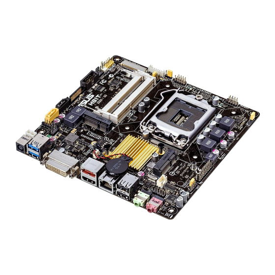
1.2.2 Screw holes Place six screws into the holes indicated by circles to secure the motherboard to the chassis. Do not overtighten the screws! Doing so can damage the motherboard. Place this side towards the rear of the chassis 1.2.3 Motherboard layout 17cm(6.7in) DC_PWR... -
Page 11: Central Processing Unit (Cpu)
Central Processing Unit (CPU) This motherboard comes with a surface mount LGA1150 socket designed for the Intel 4th generation Core™ i7 / Core™ i5 / Core™ i3, Pentium , Celeron processors. ® ® H81T H81T CPU socket LGA1150 ASUS H81T... -
Page 12: Installing The Cpu
Contact your retailer immediately if the PnP cap is missing, or if you see any damage to the PnP cap/socket contacts/motherboard components. ASUS will shoulder the cost of repair only if the damage is shipment/ transit-related. -
Page 13: Cpu Heatsink And Fan Assembly Installation
1.3.2 CPU heatsink and fan assembly installation Apply the Thermal Interface Material to the CPU heatsink and CPU before you install the heatsink and fan if necessary. ASUS H81T... - Page 14 To install the CPU heatsink and fan assembly To uninstall the CPU heatsink and fan assembly Chapter 1: Product introduction...
-
Page 15: System Memory
CPU’s capabilities and other installed devices. • The maximum 16GB memory capacity can be supported with 8GB or above DIMMs. ASUS will update the memory QVL once the DIMMs are available in the market. ASUS H81T... -
Page 16: Installing A Dimm
For system stability, use a more efficient memory cooling system to support a full memory load (2 DIMMs) or overclocking condition. • Visit the ASUS website at: www.asus.com for the latest QVL. 1.4.3 Installing a DIMM To install a DIMM... -
Page 17: Expansion Slots
IRQ assignments. Otherwise, conflicts will arise between the two PCI groups, making the system unstable and the card inoperable. 1.5.3 mini PCIe slot This motherboard supports mini PCIe slot that supports half-sized mPCIe module. ASUS H81T... -
Page 18: Jumpers
CLRTC Normal Clear RTC (Default) H81T Clear RTC RAM To erase the RTC RAM: Turn OFF the computer and unplug the power cord. Move the jumper cap from pins 1-2 (default) to pins 2-3. Keep the cap on pins 2-3 for about 5-10 seconds, then move the cap back to pins 1-2. - Page 19 CHASSIS H81T PIN 1 H81T Chassis intrusion connector Display panel backlight power selector (3-pin BLKT_PWR_SEL) BLKT_PWR_SEL H81T (Default) H81T Display panel backlight power selection Pins Setting Display panel VCC power selector (VCC_PWR_SEL) VCC_PWR_SEL H81T (Default) H81T Display panel VCC power...
-
Page 20: Connectors
Connectors 1.7.1 Rear panel connectors DC power connector. Insert the power adapter into this port. USB 3.0 ports 1 and 2. These two 9-pin Universal Serial Bus (USB) ports are for connecting USB 3.0 devices. DVI-I port. This port is for any DVI-I compatible device and are HDCP compliant, allowing playback of HD DVD, Blu-Ray and other protected content. -
Page 21: Internal Connectors
PIN 1 H81T H81T Serial port connector The COM module is purchased separately. CPU and chassis fan connectors (4-pin CPU_FAN, and 4-pin CHA_FAN) Connect the fan cables to the fan connectors on the motherboard, ensuring that the black wire of each cable matches the ground pin of the connector. - Page 22 SATA3G_1 H81T H81T SATA 3.0Gb/s connector • You must install Windows. XP Service Pack 3 or later version before using Serial ATA hard disk drives. • When using hot-plug and NCQ, set the SATA Mode Selection item in the BIOS to [AHCI].
- Page 23 HD-audio-compliant Legacy AC’97 pin definition compliant definition H81T Front panel audio connector We recommend that you connect a high-definition front panel audio module to this connector to avail of the motherboard’s high-definition audio capability. SATA power connector (15-pin SATA_PWRCON) This connector is for the SATA power cable. The power cable plug is designed to fit this connector in only one orientation.
- Page 24 H81T PIN 1 H81T TPM Connector The TPM module is purchased separately. USB 2.0 connectors (5-1 pin USB11, 10-1 pin USB910, 10-2 pin USB56) These connectors are for USB 2.0 ports. Connect the USB module cable to any of these connectors, then install the module to a slot opening at the back of the system chassis.
- Page 25 This 2-pin connector is for the chassis-mounted reset button for system reboot without turning off the system power. Display panel power button (2 pin PANEL_SW) This connector is used for the display panel power switch. PANEL_SW PIN 1 H81T H81T Display panel power button ASUS H81T 1-17...
- Page 26 BKLT_PWM BKLT_PWR BKLT_PWR BKLT_GND/Brightness_GND BKLT_GND/Brightness_GND Brightness_up Brightness_Down PIN 1 H81T Flat Panel Display Brightness DMIC connectors (4-pin DMIC) The DMIC connector is for connecting the digital microphone module used in All-in-One chassis. DMIC H81T PIN 1 H81T DMIC connectors 1-18...
-
Page 27: Onboard Leds
4 Ohms at 3 Watts (rms). SPK_OUT H81T PIN 1 H81T Internal Stereo Speakers Header Onboard LEDs Standby Power LED The motherboard comes with a standby power LED that lights up to indicate that the system is ON, in sleep mode, or in soft-off mode. This is a reminder that you should shut down the system and unplug the power cable before removing or plugging in any motherboard component. -
Page 28: Software Support
Place the Support DVD into the optical drive. If Autorun is enabled in your computer, the DVD automatically displays the Specials screen which lists the unique features of your ASUS motherboard. Click Drivers, Utilities, AHCI/RAID Driver, Manual, Contact, and Specials tabs to display their respective menus. -
Page 29: Bios Information
Managing and updating your BIOS Save a copy of the original motherboard BIOS file to a USB flash disk in case you need to restore the BIOS in the future. Copy the original motherboard BIOS using the ASUS Update utility. -
Page 30: Asus Ez Flash
2.1.3 ASUS CrashFree BIOS 3 utility The ASUS CrashFree BIOS 3 is an auto recovery tool that allows you to restore the BIOS file when it fails or gets corrupted during the updating process. You can restore a corrupted BIOS file using the motherboard support DVD or a USB flash drive that contains the updated BIOS file. -
Page 31: Recovering The Bios
2.1.4 ASUS BIOS Updater The ASUS BIOS Updater allows you to update BIOS in a DOS environment. This utility also allows you to copy the current BIOS file that you can use as a backup when the BIOS fails or gets corrupted during the updating process. - Page 32 Insert the DOS-bootable USB flash drive with the latest BIOS file and BIOS Updater to your computer’s USB port. Boot your computer. When the ASUS Logo appears, press <F8> to show the BIOS Boot Device Select Menu. Select the optical drive as the boot device. The DOS screen appears.
-
Page 33: Bios Setup Program
Using the power button, reset button, or the <Ctrl>+<Alt>+<Del> keys to force reset from a running operating system can cause damage to your data or system. We recommend you always shut down the system properly from the operating system. ASUS H81T... -
Page 34: Bios Menu Screen
The BIOS setup screens shown in this section are for reference purposes only, and may not exactly match what you see on your screen. • Visit the ASUS website at www.asus.com to download the latest BIOS file for this motherboard. •... -
Page 35: Advanced Mode
The Advanced Mode provides advanced options for experienced end-users to configure the BIOS settings. The figure below shows an example of the Advanced Mode. Refer to the following sections for the detailed configurations. To access the EZ Mode, click Exit, then select ASUS EZ Mode or press F7. ASUS H81T... -
Page 36: Menu Bar
Back button Menu items Menu bar Configuration fields General help Last modified settings Quick note Pop-up window Submenu item Navigation keys Scroll bar Menu bar The menu bar on top of the screen has the following main items: My Favorites For saving the frequently-used system settings and configuration Main For changing the basic system configuration... -
Page 37: My Favorites
This button allows you to enter notes of the activities that you have done in BIOS. Last Modified button This button shows the items that you last modified and saved in BIOS Setup. My Favorites MyFavorites is your personal space where you can easily save and access your favorite BIOS items. ASUS H81T... -
Page 38: Main Menu
Adding items to My Favorites To add frequently-used BIOS items to My Favorites: Use the arrow keys to select an item that you want to add. When using a mouse, hover the pointer to the item. Press <F4> on your keyboard or right-click on your mouse to add the item to My Favorites page. -
Page 39: Administrator Password
Select the User Password item and press <Enter>. From the Enter Current Password box, key in the current password, then press <Enter>. From the Create New Password box, key in a new password, then press <Enter>. Confirm the password when prompted. ASUS H81T 2-11... -
Page 40: Ai Tweaker Menu
To clear the user password, follow the same steps as in changing a user password, but press <Enter> when prompted to create/confirm the password. After you clear the password, the User Password item on top of the screen shows Not Installed. Ai Tweaker menu The Ai Tweaker menu items allow you to configure overclocking-related items. - Page 41 Select [Auto] to apply the CPU default Turbo Ratio setting or manually assign a 1-Core Limit value, which should be higher than or equal to the 2-Core Ratio Limit. 2-/3-/4-Core Ratio Limit [Auto] These items become configurable only when you set the CPU Core Ratio item to [Per Core]. ASUS H81T 2-13...
- Page 42 2.5.2 Min CPU Cache Ratio [Auto] Allows you to set the minimum CPU Cache Ratio. 2.5.3 Max CPU Cache Ratio [Auto] Allows you to set the maximum CPU Cache Ratio. 2.5.4 BCLK Frequency: DRAM Frequency Ratio [Auto] Allows you to set the CPU bus speed to DRAM speed ratio mode. [Auto] DRAM speed is set to the optimized settings.
-
Page 43: Dram Timing Control
Configuration options: [Auto] [1 DRAM Clock] – [15 DRAM Clock] DRAM CKE Minimum pulse width [Auto] Configuration options: [Auto] [1 DRAM Clock] – [15 DRAM Clock] DRAM CAS# Write to Latency [Auto] Configuration options: [Auto] [1 DRAM Clock] – [31 DRAM Clock] ASUS H81T 2-15... - Page 44 RTL IOL control DRAM RTL initial Value [Auto] Configuration options: [Auto] [1 DRAM Clock] – [63 DRAM Clock] DRAM RTL (CHA) [Auto] Configuration options: [Auto] [1 DRAM Clock] – [63 DRAM Clock] DRAM RTL (CHB) [Auto] Configuration options: [Auto] [1 DRAM Clock] – [63 DRAM Clock] DRAM I0-L (CHA) [Auto] Configuration options: [Auto] [Delay 1 Clock] - [Delay 15 Clock] DRAM IO-L (CHB) [Auto]...
-
Page 45: Cpu Power Management
Configuration options: [Enable Both DIMMS] [Disable DIMM0] [Disable DIMM1] [Disable Both DIMMS] Scrambler Setting [Optimized ...] Configuration options: [Optimized (ASUS)] [Default (MRC)] 2.5.10 CPU Power Management The subitems in this menu allow you to set the CPU ratio and features. - Page 46 Short Duration Package Power Limit [Auto] Allows you to limit the turbo ratio’s long duration power. Use the <+> and <-> keys to adjust the value. CPU Integrated VR Current Limit [Auto] Allows you to limit the CPU Integrated VR current. Use <+>...
- Page 47 CPU Cache Voltage Override [Auto] This item appears only when you set the CPU Cache Voltage to [Manual Mode] and allows you to set the CPU Cache voltage override. The values range from 0.001V to 1.920V with a 0.001V interval. ASUS H81T 2-19...
- Page 48 Offset Mode Sign [+] This item appears only when you set the CPU Cache Voltage to [Offset Mode] or [Adaptive Mode] and allows you to set the offset mode sign. Configuration options: [+] [-] CPU Cache Voltage Offset [Auto] This item appears only when you set the CPU Cache Voltage to [Offset Mode] or [Adaptive Mode] and allows you to set the CPU cache voltage offset.
- Page 49 Allows you to set the DRAM DATA REF Voltage on CHB. The values range from 0.3950V to 0.6300V with a 0.0050V interval 2.5.23 CPU Spread Spectrum [Auto] [Auto] Automatic configuration. [Disabled] Enhances the BCLK overclocking ability. [Enabled] Sets to [Enabled] for EMI control. ASUS H81T 2-21...
-
Page 50: Advanced Menu
Advanced menu The Advanced menu items allow you to change the settings for the CPU and other system devices. Be cautious when changing the settings of the Advanced menu items. Incorrect field values can cause the system to malfunction. 2.6.1 CPU Configuration The items in this menu show the CPU-related information that the BIOS automatically detects. - Page 51 The operating system controls the CPU speed. Turbo Mode [Enabled] Allows you to set the processor cores to run faster than the marked frequency in a specific condition. Configuration options: [Enabled] [Disabled] Turbo Mode is only available on selected CPU models only. ASUS H81T 2-23...
-
Page 52: Pch Configuration
CPU C states [Auto] [Auto] Automatic configuration. [Enabled] Enables the CPU C states. [Disabled] Disables the CPU C states. The following items appear only when you set the CPU C states to [Enabled]. Enhanced C1 state [Enabled] [Enabled] Enables enhanced C1 state. [Disabled] Disables enhanced C1 state. -
Page 53: Sata Configuration
SATA Mode Selection [AHCI] Allows you to set the SATA configuration. [Disabled] Disables the SATA function. [IDE] Set to [IDE] when you want to use the Serial ATA hard disk drives as Parallel ATA physical storage devices. ASUS H81T 2-25... -
Page 54: System Agent Configuration
[AHCI] Set to [AHCI] when you want the SATA hard disk drives to use the AHCI (Advanced Host Controller Interface). The AHCI allows the onboard storage driver to enable advanced Serial ATA features that increases storage performance on random workloads by allowing the drive to internally optimize the order of commands. - Page 55 Configuration options: [100 ms] [200 ms] [250 ms] [300 ms] Video_Data OFF to Panel_Vcc OFF (T13) [20 ms] Configuration options: [10 ms] [20 ms] [30 ms] [40 ms] Min Panel_Vcc OFF Time (T15) [600 ms] Configuration options: [600 ms] [700 ms] [800 ms] [1000 ms] ASUS H81T 2-27...
-
Page 56: Dmi Configuration
LVDS Spread Spectrum Control [+/- 0.5% Center Spread] Adjusts LVDS spread spectrum clocking. Configuration options: [Disabled] [+/- 0.5% Center Spread] [+/- 1% Center Spread] DMI Configuration Allows you to control various DMI functions. DMI Gen 2 [Auto] Allows you to enable or disable DMI Gen 2. Configuration options: [Auto] [Enabled] [Disabled] DMI Link ASPM Control [Auto] Allows you to enable or disable the control of Active State Power Management on SA... -
Page 57: Platform Misc Configuration
This item disables or enables AI Charger while the system is in S5 mode. Configuration options: [Enabled] [Disabled] Serial Port Configuration The sub-items in this menu allow you to set the serial port configuration. Serial Port [Enabled] Allows you to enable or disable the serial port (COM).Configuration options: [Enabled] [Disabled] ASUS H81T 2-29... -
Page 58: Network Stack Configuration
Change Settings [IO=3F8h; IRQ=4] This item appears only when you set the Serial Port to [Enabled] and allows you to select the Serial Port base address. Configuration options: [IO=3F8h; IRQ=4] [IO=2F8h; IRQ=3] [IO=3E8h; IRQ=4] [IO=2E8h; IRQ=3] 2.6.9 ErP Ready [Disabled] Allows you to switch off some power at S4+S5 or S5 to get the system ready for ErP requirement. -
Page 59: Monitor Menu
CPU Input Voltage (VCCIN), CPU Core Voltage, 3.3V Voltage, 5V Voltage, 12V Voltage The onboard hardware monitor automatically detects the voltage output through the onboard voltage regulators. Select Ignore if you do not want to detect this item. ASUS H81T 2-31... - Page 60 2.7.4 CPU Q-Fan Control [Enabled] [Disabled] Disables the CPU Q-Fan control feature. [Enabled] Enables the CPU Q-Fan control feature. CPU Fan Speed Low Limit [200 RPM] This item appears only when you enable the CPU Q-Fan Control feature and allows you to disable or set the CPU fan warning speed.
- Page 61 60% to 100%. When the chassis temperature is under 40ºC, the chassis fan will operate at the minimum duty cycle. 2.7.6 Chassis Intrude Support [Disabled] This item allows you to enable or disable the chassis intrusion support function. Configuration options: [Disabled] [Enabled] ASUS H81T 2-33...
-
Page 62: Boot Menu
Boot menu The Boot menu items allow you to change the system boot options. Scroll down to display the following items: 2.8.1 Fast Boot [Enabled] [Enabled] Select to accelerate the boot speed. [Disabled] Select to go back to normal boot. The following four items appear when you set Fast Boot to [Enabled]. - Page 63 [Force BIOS] The third-party ROM messages will be forced to display during the boot sequence. [Keep Current] The third-party ROM messages will be displayed only if the third-party manufacturer had set the add-on device to do so. ASUS H81T 2-35...
-
Page 64: Secure Boot
2.8.6 Interrupt 19 Capture [Disabled] [Enabled] Allows the option ROMs to trap Interrupt 19. [Disabled] Disables this function. 2.8.7 Setup Mode [EZ Mode] [Advanced Mode] Sets Advanced Mode as the default screen for entering the BIOS setup program. [EZ Mode] Sets EZ Mode as the default screen for entering the BIOS setup program. -
Page 65: Key Management
Allows you to load the downloaded PK from a USB storage device. The PK file must be formatted as a UEFI variable structure with time-based authenticated variable. KEK Management The KEK (Key-exchange Key or Key Enrollment Key) manages the Signature database (db) and Revoked Signature database (dbx). ASUS H81T 2-37... -
Page 66: Dbx Management
Key-exchange Key (KEK) refers to Microsoft Secure Boot Key-Enrollment Key (KEK). ® Delete the KEK Allows you to delete the KEK from your system. Configuration options: [Yes] [No] Load KEK from File Allows you to load the downloaded KEK from a USB storage device. Append KEK from file Allows you to load the additional KEK from a storage device for an additional db and dbx loaded management. -
Page 67: Boot Option Priorities
• To select the boot device during system startup, press <F8> when ASUS Logo appears. • To access Windows OS in Safe Mode, do any of the following: •... -
Page 68: Tools Menu
<Enter> to display the submenu. 2.9.1 ASUS EZ Flash 2 Utility Allows you to run ASUS EZ Flash 2. Press [Enter] to launch the ASUS EZ Flash 2 screen. For more details, see section 2.1.2 ASUS EZ Flash 2. 2.9.2 ASUS Overclocking Profile This item allows you to store or load multiple BIOS settings. -
Page 69: Exit Menu
This option allows you to exit the Setup program without saving your changes. When you select this option or if you press <Esc>, a confirmation window appears. Select Yes to discard changes and exit. ASUS EZ Mode This option allows you to enter the EZ Mode screen. Launch EFI Shell from filesystem device This option allows you to attempt to launch the EFI Shell application (shellx64.efi) from one of... -
Page 70: Appendices
Cet appareil est conforme aux normes CNR exemptes de licence d’Industrie Canada. Le fonctionnement est soumis aux deux conditions suivantes : (1) cet appareil ne doit pas provoquer d’interférences et (2) cet appareil doit accepter toute interférence, y compris celles susceptibles de provoquer un fonctionnement non souhaité de l’appareil. H81T... -
Page 71: Canadian Department Of Communications Statement
ASUS Recycling/Takeback Services ASUS recycling and takeback programs come from our commitment to the highest standards for protecting our environment. We believe in providing solutions for you to be able to responsibly recycle our products, batteries, other components as well as the packaging materials. -
Page 72: Asus Contact Information
+1-510-739-3777 +1-510-608-4555 Web site http://usa.asus.com Technical Support Support fax +1-812-284-0883 General support +1-812-282-2787 Online support http://support.asus.com/techserv/techserv.aspx ASUS COMPUTER GmbH (Germany and Austria) Address Harkort Str. 21-23, D-40880 Ratingen, Germany +49-2102-959931 Web site http://www.asus.com/de Online contact http://eu-rma.asus.com/sales Technical Support Telephone +49-2102-5789555... - Page 73 Appendices...