Table of Contents
Advertisement
Advertisement
Table of Contents

Related Manuals for Asus H81M-E R2.0


Summary of Contents for Asus H81M-E R2.0
- Page 1 H81M-E R2.0...
- Page 2 Product warranty or service will not be extended if: (1) the product is repaired, modified or altered, unless such repair, modification of alteration is authorized in writing by ASUS; or (2) the serial number of the product is defaced or missing.
-
Page 3: Table Of Contents
Contents Safety information ...................... iv About this guide ......................iv Package contents ....................... vi H81M-E R2.0 specifications summary..............vi Product introduction Before you proceed ..................1-1 Motherboard overview ................. 1-1 Central Processing Unit (CPU) ..............1-4 System memory .................... 1-7 Expansion slots .................... -
Page 4: Safety Information
Safety information Electrical safety • To prevent electrical shock hazard, disconnect the power cable from the electrical outlet before relocating the system. • When adding or removing devices to or from the system, ensure that the power cables for the devices are unplugged before the signal cables are connected. If possible, disconnect all power cables from the existing system before you add a device. -
Page 5: Conventions Used In This Guide
Refer to the following sources for additional information and for product and software updates. ASUS websites The ASUS website provides updated information on ASUS hardware and software products. Refer to the ASUS contact information. Optional documentation Your product package may include optional documentation, such as warranty flyers, that may have been added by your dealer. -
Page 6: Package Contents
® * Hyper DIMM support is subject to the physical characteristics of individual CPUs. Please refer to Memory QVL for details. ** Refer to www.asus.com for the latest Memory QVL (Qualified Vendors List). ® *** Due to Intel chipset limitations, DDR3 1600MHz and higher memory modules on XMP mode will run at the maximum transfer rate of DDR3 1600MHz. - Page 7 - 8 x USB 2.0/1.1 ports (4 ports at mid-board, 4 ports at the rear panel) ASUS 5X Protection ASUS unique features - ASUS motherboards safeguard your PC with 5X Protection: DIGI+VRM, DRAM Fuse, ESD Guards, High-Quality 5K Solid Capacitors, and Stainless Steel Back I/O to ensure the best quality, reliability, and durability...
- Page 8 64 Mb Flash ROM, UEFI AMI BIOS, PnP, DMI2.0, WfM2.0, SM BIOS 2.7, BIOS features ACPI 2.0a, Multi-language BIOS, ASUS EZ Flash 2, ASUS CrashFree BIOS 3, My Favorites, Quick Note, Last Modified log, F12 PrintScreen, F3 Shortcut functions and ASUS DRAM SPD (Serial Presence Detect) memory...
-
Page 9: Product Introduction
Failure to do so can cause you physical injury and damage motherboard components. 1.2.1 Placement direction When installing the motherboard, ensure that you place it into the chassis in the correct orientation. The edge with external ports goes to the rear part of the chassis as indicated in the image below. ASUS H81M-E R2.0... -
Page 10: Screw Holes
1.2.2 Screw holes Place six screws into the holes indicated by circles to secure the motherboard to the chassis. Do not overtighten the screws! Doing so can damage the motherboard. Place this side towards the rear of the chassis H81M-E R2.0 Chapter 1: Product introduction... -
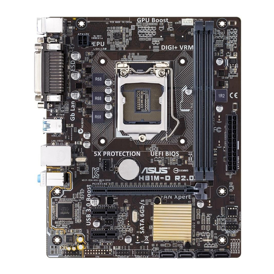
Page 11: Motherboard Layout
Motherboard layout 17.5cm(6.9in) CPU_FAN KBMS DIGI +VRM ATX12V USB56 LGA1150 USB3_12 LAN_USB34 CHA_FAN BATTERY AUDIO H81M-E R2.0 PCIEX16 8111GR 64Mb PCIEX1_1 BIOS Super Intel ® SPEAKER PCIEX1_2 F_PANEL 887- VD2 USB910 USB1112 SATA6G_1 SATA6G_2 SATA3G_1 SATA3G_2 AAFP ASUS H81M-E R2.0... -
Page 12: Central Processing Unit (Cpu)
10. Clear RTC RAM (2-pin CLRTC) 1-11 11. Digital audio connector (4-1 pin SPDIF_OUT) 1-14 12. Front panel audio connector (10-1 pin AAFP) 1-14 Central Processing Unit (CPU) This motherboard comes with a surface mount LGA1150 socket designed for the Intel ® 4th/4th generation Core™ i7 / Core™ i5 / Core™ i3, Pentium and Celeron processors. ® ® H81M-E R2.0 H81M-E R2.0 CPU socket LGA1150 Unplug all power cables before installing the CPU. • Upon purchase of the motherboard, ensure that the PnP cap is on the socket and the socket contacts are not bent. Contact your retailer immediately if the PnP cap is missing, or if you see any damage to the PnP cap/socket contacts/motherboard components. ASUS will shoulder the cost of repair only if the damage is shipment/ transit-related. • Keep the cap after installing the motherboard. ASUS will process Return Merchandise Authorization (RMA) requests only if the motherboard comes with the cap on the LGA1150 socket. • The product warranty does not cover damage to the socket contacts resulting from incorrect CPU installation/removal, or misplacement/loss/incorrect removal of the PnP cap. -
Page 13: Installing The Cpu
1.3.1 Installing the CPU ASUS H81M-E R2.0... -
Page 14: Cpu Heatsink And Fan Assembly Installation
1.3.2 CPU heatsink and fan assembly installation Apply the Thermal Interface Material to the CPU heatsink and CPU before you install the heatsink and fan if necessary. To install the CPU heatsink and fan assembly Chapter 1: Product introduction... -
Page 15: System Memory
To uninstall the CPU heatsink and fan assembly System memory 1.4.1 Overview This motherboard comes with two Double Data Rate 3 (DDR3) Dual Inline Memory Module (DIMM) sockets. A DDR3 module is notched differently from a DDR or DDR2 module. DO NOT install a DDR or DDR2 memory module to the DDR3 slot. According to Intel CPU spec, DIMM voltage below 1.65V is recommended to protect the ® CPU. Channel Sockets Channel A DIMM_A1 Channel B DIMM_B1 H81M-E R2.0 H81M-E R2.0 240-pin DDR3 DIMM sockets ASUS H81M-E R2.0... -
Page 16: Memory Configurations
Use a maximum of 3GB system memory if you are using a 32-bit Windows OS. ® I nstall a 64-bit Windows OS if you want to install 4GB or more on the ® motherboard. • This motherboard does not support DIMMs made up of 512 megabits (Mb) chips or less. • Memory modules with memory frequency higher than 2133 MHz and its corresponding timing or the loaded X.M.P. Profile is not the JEDEC memory standard. The stability and compatibility of these memory modules depend on the CPU’s capabilities and other installed devices. • The maximum 16GB memory capacity can be supported with 8GB or above DIMMs. ASUS will update the memory QVL once the DIMMs are available in the market. • The default memory operation frequency is dependent on its Serial Presence Detect (SPD), which is the standard way of accessing information from a memory module. Under the default state, some memory modules for overclocking may operate at a lower frequency than the vendor-marked value. • For system stability, use a more efficient memory cooling system to support a full memory load (2 DIMMs) or overclocking condition. • Refer to www.asus.com for the latest Memory QVL (Qualified Vendors List) 1.4.3 Installing a DIMM Chapter 1: Product introduction... -
Page 17: Expansion Slots
To remove a DIMM Expansion slots In the future, you may need to install expansion cards. The following sub-sections describe the slots and the expansion cards that they support. Unplug the power cord before adding or removing expansion cards. Failure to do so may cause you physical injury and damage motherboard components. ASUS H81M-E R2.0... -
Page 18: Installing An Expansion Card
1.5.1 Installing an expansion card To install an expansion card: Before installing the expansion card, read the documentation that came with it and make the necessary hardware settings for the card. Remove the system unit cover (if your motherboard is already installed in a chassis). Remove the bracket opposite the slot that you intend to use. Keep the screw for later use. Align the card connector with the slot and press firmly until the card is completely seated on the slot. Secure the card to the chassis with the screw you removed earlier. Replace the system cover. 1.5.2 Configuring an expansion card After installing the expansion card, configure it by adjusting the software settings. Turn on the system and change the necessary BIOS settings, if any. See Chapter 2 for information on BIOS setup. Assign an IRQ to the card. Install the software drivers for the expansion card. When using PCI cards on shared slots, ensure that the drivers support “Share IRQ” or that the cards do not need IRQ assignments. Otherwise, conflicts will arise between the two PCI groups, making the system unstable and the card inoperable. -
Page 19: Headers
Headers Clear RTC RAM (2-pin CLRTC) This header allows you to clear the Real Time Clock (RTC) RAM in CMOS. You can clear the CMOS memory of date, time, and system setup parameters by erasing the CMOS RTC RAM data. The onboard button cell battery powers the RAM data in CMOS, which include system setup information such as system passwords. CLRTC H81M-E R2.0 PIN 1 H81M-E R2.0 Clear RTC RAM To erase the RTC RAM: Turn OFF the computer and unplug the power cord. Use a metal object such as a screwdriver to short the two pins. Plug the power cord and turn ON the computer. Hold down the <Del> key during the boot process and enter BIOS setup to re- enter data. • If the steps above do not help, remove the onboard battery and short the two pins again to clear the CMOS RTC RAM data. After clearing the CMOS, reinstall the battery. • You do not need to clear the RTC when the system hangs due to overclocking. For system failure due to overclocking, use the CPU Parameter Recall (C.P.R.) feature. Shut down and reboot the system, then the BIOS automatically resets parameter settings to default values. -
Page 20: Connectors
Connectors 1.7.1 Rear panel connectors PS/2 Mouse port (green). This port is for a PS/2 mouse. Video Graphics Adapter (VGA) port. This 15-pin port is for a VGA monitor or other VGA-compatible devices. LAN (RJ-45) port. This port allows Gigabit connection to a Local Area Network (LAN) through a network hub. Refer to the table below for the LAN port LED indications. LAN port LED indications Activity/Link LED Speed LED Speed Status Description Status Description Activity Link No link 10Mbps connection Orange Linked ORANGE 100Mbps connection Orange (Blinking) Data activity... - Page 21 USB 2.0 ports 3 and 4. These two 4-pin Universal Serial Bus (USB) ports are for USB 2.0/1.1 devices. USB 3.0 ports 1 and 2. These two 9-pin Universal Serial Bus (USB) ports connect to USB 3.0/2.0 devices. • Due to USB 3.0 controller limitations, USB 3.0 devices can only be used under a Windows OS environment and after USB 3.0 driver installation. ® • The plugged USB 3.0 device may run on xHCI or EHCI mode, depending on the operating system’s setting. • USB 3.0 devices can only be used for data storage. • We strongly recommend that you connect USB 3.0 devices to USB 3.0 ports for faster and better performance from your USB 3.0 devices. USB 2.0 ports 5 and 6. These two 4-pin Universal Serial Bus (USB) ports are for USB 2.0/1.1 devices. Serial port. This 9-pin COM port is for pointing devices or other serial devices. PS/2 keyboard port (purple). This port is for a PS/2 keyboard. ASUS H81M-E R2.0 1-13...
-
Page 22: Internal Connectors
Front panel audio connector (10-1 pin AAFP) This connector is for a chassis-mounted front panel audio I/O module that supports either HD Audio or legacy AC`97 audio standard. Connect one end of the front panel audio I/O module cable to this connector. AAFP PIN 1 PIN 1 H81M-E R2.0 HD-audio-compliant Legacy AC’97 pin definition compliant definition H81M-E R2.0 Front panel audio connector • We recommend that you connect a high-definition front panel audio module to this connector to avail of the motherboard’s high-definition audio capability. • If you want to connect a high-definition front panel audio module to this connector, set the Front Panel Type item in the BIOS setup to [HD]. If you want to connect an AC’97 front panel audio module to this connector, set the item to [AC97]. By default, this connector is set to [HD]. Digital audio connector (4-1 pin SPDIF_OUT) This connector is for an additional Sony/Philips Digital Interface (S/PDIF) port. Connect the S/PDIF Out module cable to this connector, then install the module to a slot opening at the back of the system chassis. -
Page 23: Cpu And Chassis Fan Connectors
CPU and chassis fan connectors (4-pin CPU_FAN, 4-pin CHA_FAN) Connect the fan cables to the fan connectors on the motherboard, ensuring that the black wire of each cable matches the ground pin of the connector. CPU_FAN CHA_FAN H81M-E R2.0 H81M-E R2.0 Fan connectors Do not forget to connect the fan cables to the fan connectors. Insufficient air flow inside the system may damage the motherboard components. These are not jumpers! Do not place jumper caps on the fan connectors! The CPU_FAN connector supports a CPU fan of maximum 1A (12 W) fan power. Only the 4-pin CPU fan and chassis fan support the ASUS Fan Xpert feature. USB 2.0 connectors (10-1 pin USB910, USB1112) These connectors are for USB 2.0 ports. Connect the USB module cable to any of... -
Page 24: Atx Power/Speaker Connector
Power OK -5 Volts +5 Volts +5 Volts PSON# H81M-E R2.0 +3 Volts -12 Volts +3 Volts +3 Volts PIN 1 H81M-E R2.0 ATX power connectors • We recommend that you use an ATX 12V Specification 2.0-compliant power supply unit (PSU) with a minimum of 300W power rating. This PSU type has 24-pin and 4-pin power plugs. • DO NOT forget to connect the 4-pin ATX +12V power plug. Otherwise, the system will not boot up. • We recommend that you use a PSU with higher power output when configuring a system with more power-consuming devices or when you intend to install additional devices. The system may become unstable or may not boot up if the power is inadequate. - Page 25 Intel H81 Serial ATA 3.0 Gb/s connectors (7-pin SATA3G 1~2 [black]) ® These connectors connect to Serial ATA 3.0 Gb/s hard disk drives via Serial ATA 3.0 Gb/s signal cables. H81M-E R2.0 H81M-E R2.0 SATA 3.0Gb/s connectors When using hot-plug and NCQ, set the SATA Mode Selection item in the BIOS to [AHCI]. Intel H81 Serial ATA 6.0Gb/s connectors (7-pin SATA6G_1~2 [gray]) ® These connectors connect to Serial ATA 6.0 Gb/s hard disk drives via Serial ATA 6.0 Gb/s signal cables. H81M-E R2.0 H81M-E R2.0 SATA 6.0Gb/s connectors...
-
Page 26: System Panel Connector
System panel connector (10-1 pin PANEL) This connector supports several chassis-mounted functions. F_PANEL +PWR_LED- PWR BTN PIN 1 H81M-E R2.0 +HDD_LED- RESET H81M-E R2.0 System panel connector • System power LED (2-pin +PWR_LED-) This 2-pin connector is for the system power LED. Connect the chassis power LED cable to this connector. The system power LED lights up when you turn on the system power, and blinks when the system is in sleep mode. • Hard disk drive activity LED (2-pin +HDD_LED-) This 2-pin connector is for the HDD Activity LED. Connect the HDD Activity LED cable to this connector. The HDD LED lights up or flashes when data is read from or written... -
Page 27: Software Support
To run the Support DVD Place the Support DVD into the optical drive. If Autorun is enabled in your computer, the DVD automatically displays the Specials screen which lists the unique features of your ASUS motherboard. Click Drivers, Utilities, AHCI Driver, Manual, Contact and Specials tabs to display their respective menus. The following screen is for reference only. Click an icon to display Support DVD/motherboard information Click to display more items Click an item to install If Autorun is NOT enabled in your computer, browse the contents of the Support DVD to locate the file ASSETUP.EXE from the BIN folder. Double-click the ASSETUP.EXE to run the DVD. ASUS H81M-E R2.0 1-19... - Page 28 1-20 Chapter 1: Product introduction...
-
Page 29: Bios Information
Managing and updating your BIOS Save a copy of the original motherboard BIOS file to a USB flash disk in case you need to restore the BIOS in the future. Copy the original motherboard BIOS using the ASUS Update utility. -
Page 30: Asus Ez Flash
2.1.2 ASUS EZ Flash 2 The ASUS EZ Flash 2 feature allows you to update the BIOS without using an OS‑based utility. Before you start using this utility, download the latest BIOS file from the ASUS website at www.asus.com. To update the BIOS using EZ Flash 2: Insert the USB flash disk that contains the latest BIOS file to the USB port. -
Page 31: Asus Crashfree Bios 3 Utility
2.1.3 ASUS CrashFree BIOS 3 utility The ASUS CrashFree BIOS 3 is an auto recovery tool that allows you to restore the BIOS file when it fails or gets corrupted during the updating process. You can restore a corrupted BIOS file using the motherboard support DVD or a USB flash drive that contains the updated BIOS file. - Page 32 Boot your computer then press <F8> to launch the select boot device screen. When the select boot device screen appears, insert the Support DVD into the optical drive then select the optical drive as the boot device. Please select boot device: ASUS DVD-E818A6T (4069MB) USB DISK 2.0 (3824MB) UEFI: (FAT) USB DISK 2.0 (3824MB)
- Page 33 DO NOT shut down or reset the system while updating the BIOS to prevent system boot failure. Ensure to load the BIOS default settings to ensure system compatibility and stability. Select the Load Optimized Defaults item under the Exit BIOS menu. See Chapter 2 of your motherboard user guide for details. ASUS H81M-E R2.0...
-
Page 34: Bios Setup Program
The BIOS setup screens shown in this section are for reference purposes only, and may not exactly match what you see on your screen. • Visit the ASUS website at www.asus.com to download the latest BIOS file for this motherboard. •... - Page 35 Displays the Advanced mode menus • The boot device options vary depending on the devices you installed to the system. • The Boot Menu(F8) button is available only when the boot device is installed to the system. ASUS H81M-E R2.0...
-
Page 36: Advanced Mode
The Advanced Mode provides advanced options for experienced end‑users to configure the BIOS settings. The figure below shows an example of the Advanced Mode. Refer to the following sections for the detailed configurations. To access the EZ Mode, click Exit, then select ASUS EZ Mode. Back button Menu items... -
Page 37: Main Menu
Be cautious when changing the settings of the Ai Tweaker menu items. Incorrect field values can cause the system to malfunction. The configuration options for this section vary depending on the CPU and DIMM model you installed on the motherboard. ASUS H81M-E R2.0... - Page 38 Scroll down to display the following items: Scroll down to display the following items: 2-10 Chapter 2: Getting started...
-
Page 39: Advanced Menu
The Advanced menu items allow you to change the settings for the CPU and other system devices. Be cautious when changing the settings of the Advanced menu items. Incorrect field values can cause the system to malfunction. ASUS H81M-E R2.0 2-11... -
Page 40: Monitor Menu
Monitor menu The Monitor menu displays the system temperature/power status, and allows you to change the fan settings. Scroll down to display the following items: 2-12 Chapter 2: Getting started... -
Page 41: Boot Menu
Boot menu The Boot menu items allow you to change the system boot options. Scroll down to display the following items: ASUS H81M-E R2.0 2‑13... -
Page 42: Tools Menu
Tools menu The Tools menu items allow you to configure options for special functions. Select an item then press <Enter> to display the submenu. Exit menu The Exit menu items allow you to load the optimal default values for the BIOS items, and save or discard your changes to the BIOS items. -
Page 43: Appendices
Cet appareil est conforme aux normes CNR exemptes de licence d’Industrie Canada. Le fonctionnement est soumis aux deux conditions suivantes : (1) cet appareil ne doit pas provoquer d’interférences et (2) cet appareil doit accepter toute interférence, y compris celles susceptibles de provoquer un fonctionnement non souhaité de l’appareil. H81M-E R2.0... -
Page 44: Canadian Department Of Communications Statement
ASUS Recycling/Takeback Services ASUS recycling and takeback programs come from our commitment to the highest standards for protecting our environment. We believe in providing solutions for you to be able to responsibly recycle our products, batteries, other components as well as the packaging materials. -
Page 45: Asus Contact Information
+1-510-739-3777 +1-510-608-4555 Web site http://www.asus.com/us/ Technical Support Support fax +1-812-284-0883 General support +1-812-282-2787 Online support http://www.service.asus.com/ ASUS COMPUTER GmbH (Germany and Austria) Address Harkort Str. 21-23, D-40880 Ratingen, Germany +49-2102-959931 Web site http://www.asus.com/de Online contact http://eu-rma.asus.com/sales Technical Support Telephone +49-2102-5789555... - Page 46 Appendices...