Advertisement
Quick Links
PARTS AND OPERATION MANUAL
PARTS AND OPERATION MANUAL
Table of Contents
MQ POWER
DCA-100SSJU
WHISPERWATT
GENERATOR
(Standard)
PARTS LIST NO. M3870300174
S/N UP TO 7400295-100SSJU
S/N FROM 7400296~100SSJU2
Revision #2 (05/03/01)
MULTIQUIP INC.
18910 WILMINGTON AVE.
CARSON, CALIFORNIA 90746 FAX: 800-672-7877
310-537-3700
800-421-1244
FAX: 310-537-3927
E-mail:mq@multiquip.com
TM
PARTS DEPARTMENT:
800-427-1244
SERVICE DEPARTMENT:
800-835-2551
FAX: 310-638-8046
•
www:multiquip.com
Advertisement

Related Manuals for MULTIQUIP Power WHISPERWATT DCA-100SSJU


Summary of Contents for MULTIQUIP Power WHISPERWATT DCA-100SSJU
- Page 1 PARTS AND OPERATION MANUAL PARTS AND OPERATION MANUAL Table of Contents MQ POWER DCA-100SSJU WHISPERWATT GENERATOR (Standard) PARTS LIST NO. M3870300174 S/N UP TO 7400295-100SSJU S/N FROM 7400296~100SSJU2 Revision #2 (05/03/01) MULTIQUIP INC. PARTS DEPARTMENT: 18910 WILMINGTON AVE. 800-427-1244 CARSON, CALIFORNIA 90746 FAX: 800-672-7877...
- Page 2 Table of Contents PAGE 2 — DCA-100SSJU — PARTS AND OPERATION MANUAL (STD) — REV. #2 (05/03/01)
- Page 3 800/427-1244 or 310/537-3700 FAX: 800/672-7877 or 310/637-3284 SERVICE DEPARTMENT 800/835-2551 or 310/537-3700 FAX: 310/638-8046 WARRANTY DEPARTMENT 800/835-2551 or 310/537-3700 FAX: 310/638-8046 MAIN 800/421-1244 or 310/537-3700 FAX: 310/537-3927 DCA-100SSJU — PARTS AND OPERATION MANUAL (STD)— REV. #2 (05/03/01) — PAGE 3...
- Page 4 Pre Setup ............. 44-47 notice Load Application ............48 Generator Start-up Procedure (Manual) ....49-51 Generator Start-up Procedure (Auto) ......52 Generator Shutdown Procedure ......... 53 Maintenance ............54-55 PAGE 4 — DCA-100SSJU — PARTS AND OPERATION MANUAL (STD) — REV. #2 (05/03/01)
- Page 5 10+ line items. Toll-free FAX: 800/6-PARTS-7 • 800-672-7877 *DISCOUNTS ARE SUBJECT TO CHANGE* Fax order discount and UPS special programs revised June 1, 1995 DCA-100SSJU — PARTS AND OPERATION MANUAL (STD)— REV. #2 (05/03/01) — PAGE 5...
- Page 6 An explosion or fire could result causing severe bodily harm or even death. Topping-off to filler port is dangerous, as it tends to spill fuel. PAGE 6 — DCA-100SSJU — PARTS AND OPERATION MANUAL (STD) — REV. #2 (05/03/01)
- Page 7 Make sure power connecting cables are securely connected to the generator’s output terminals, insufficient tightening of the terminal connections may cause damage to the generator and electrical shock. DCA-100SSJU — PARTS AND OPERATION MANUAL(STD)— REV. #2 (05/03/01) — PAGE 7...
- Page 8 When loading the generator on a truck, be sure to use the front and back frame bars as a means to secure the generator during transport. PAGE 8 — DCA-100SSJU — PARTS AND OPERATION MANUAL (STD) — REV. #2 (05/03/01)
- Page 9 Also know the phone numbers of the nearest ambulance , DO NOT pour waste, oil, coolant or fuel directly onto the doctor and fire department . ground, down a drain or into any water source. DCA-100SSJU — PARTS AND OPERATION MANUAL (STD)— REV. #2 (05/03/01) — PAGE 9...
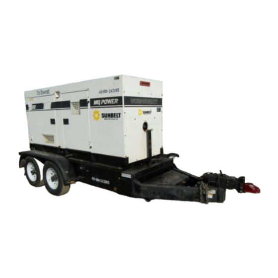
- Page 10 Also check the tire tread wear on both vehicles. DO NOT transport generator with fuel in tank. ALWAYS make sure the trailer is equipped with a "Safety Chain". Figure 1. Generator with Trailer PAGE 10 — DCA-100SSJU — PARTS AND OPERATION MANUAL (STD) — REV. #2 (05/03/01)
- Page 11 5. Frame Width - This measurement is from fender to fender. 6. Jack Stand - Trailer support device with maximum pound requirement from the tongue of the trailer. DCA-100SSJU — PARTS AND OPERATION MANUAL (STD)— REV. #2 (05/03/01) — PAGE 11...
- Page 12 " 7 " 4 " 4 " 2 " 3 " 8 " 3 " 8 " 3 " 4 " 6 " 4 " 6 PAGE 12 — DCA-100SSJU — PARTS AND OPERATION MANUAL (STD) — REV. #2 (05/03/01)
- Page 13 " 7 " 3 X " " 7 " 3 X " " 7 " 3 X " " 7 X " " 7 X " " 7 DCA-100SSJU — PARTS AND OPERATION MANUAL (STD)— REV. #2 (05/03/01) — PAGE 13...
- Page 14 7. Replace the adjusting hole cover and lower the trailer to the ground. 8. Repeat steps 1 through 6 on the remaining brakes. PAGE 14 — DCA-100SSJU — PARTS AND OPERATION MANUAL (STD) — REV. #2 (05/03/01)
- Page 15 Brake section. Reference Table 6 for hydraulic brake lines should be periodically checked for cracks, kinks, or troubleshooting guidelines. blockage. Figure 3. Hydraulic Brake Components DCA-100SSJU — PARTS AND OPERATION MANUAL (STD)— REV. #2 (05/03/01) — PAGE 15...
- Page 16 CAUTION: NOTE ALWAYS wear safety glasses when removing Figure 4. Suspension Components or installing force fitted parts. Failure to comply may result in serious injury. PAGE 16 — DCA-100SSJU — PARTS AND OPERATION MANUAL (STD) — REV. #2 (05/03/01)
- Page 17 " 2 " 3 " 4 Figure 5. Lug Nut Tightening Sequence " 5 " 6 NOTE NEVER use an pneumatic air gun to tighten wheel lug nuts. DCA-100SSJU — PARTS AND OPERATION MANUAL (STD)— REV. #2 (05/03/01) — PAGE 17...
- Page 18 Table of Contents DCA-100SSJU — TRAILER WIRING DIAGRAMS NOTE: LIGHTS ARE ORIENTED FROM THE DRIVER’S SEAT PAGE 18 — DCA-100SSJU — PARTS AND OPERATION MANUAL (STD) — REV. #2 (05/03/01)
- Page 19 REPLACE NOISY BRAKES IS THE SYSTEM LUBRICATED LUBRICATE IS THE BRAKE COMPONENTS CORRECT REPLACE AND CORRECT DRAGGING BRAKES IS THE BEARINGS OF THE W HEEL ADJUSTED ADJUST DCA-100SSJU — PARTS AND OPERATION MANUAL (STD)— REV. #2 (05/03/01) — PAGE 19...
- Page 20 IS THE BRAKE LINING THICKNESS CORRECT OR IN RIGHT WRONG INSTALL NEW SHOES AND LININGS POSITION IS THERE ENOUGH BRAKE FLUID OR CORRECT FLUID REPLACE RUBBER PARTS FILL WITH DOT FLUID PAGE 20 — DCA-100SSJU — PARTS AND OPERATION MANUAL (STD) — REV. #2 (05/03/01)
- Page 21 The illustration below and on the preceding pages show the decals as they appear on the machine. Should any of these decals become unreadable, replacements can be obtained from your dealer. DCA-100SSJU — PARTS AND OPERATION MANUAL (STD)— REV. #2 (05/03/01) — PAGE 21...
- Page 22 Table of Contents DCA-100SSJU — GENERATOR DECALS PAGE 22 — DCA-100SSJU — PARTS AND OPERATION MANUAL (STD) — REV. #2 (05/03/01)
- Page 23 Table of Contents DCA-100SSJU — SPECIFICATIONS l l u DCA-100SSJU — PARTS AND OPERATION MANUAL (STD)— REV. #2 (05/03/01) — PAGE 23...
- Page 24 " 2 Load GFCI Circuit Breakers 120V@ 20amps creases frequency variation to ±0.25%. Control Box The “Control Box” is provided with the following: " Main Circuit Breaker 250 amps " Over-Current Relay PAGE 24 — DCA-100SSJU — PARTS AND OPERATION MANUAL (STD) — REV. #2 (05/03/01)
- Page 25 Table of Contents DCA-100SSJU — MAJOR COMPONENTS Figure 6. Major Components DCA-100SSJU — PARTS AND OPERATION MANUAL (STD)— REV. #2 (05/03/01) — PAGE 25...
- Page 26 Table of Contents DCA-100SSJU — DIMENSIONS (TOP, SIDE AND FRONT) Figure 7. Dimensions PAGE 26 — DCA-100SSJU — PARTS AND OPERATION MANUAL (STD) — REV. #2 (05/03/01)
- Page 27 NOTE PAGE DCA-100SSJU — PARTS AND OPERATION MANUAL (STD)— REV. #2 (05/03/01) — PAGE 27...
- Page 28 Table of Contents DCA-100SSJU — CONTROL PANEL Figure 8. Control Panel PAGE 28 — DCA-100SSJU — PARTS AND OPERATION MANUAL (STD) — REV. #2 (05/03/01)
- Page 29 Frequency Meter – Indicates the output frequency in hertz (Hz). Normally 60 Hz ±1 Hz . AC Voltmeter – Indicates the single phase output voltage present at the UNV terminals. DCA-100SSJU — PARTS AND OPERATION MANUAL (STD)— REV. #2 (05/03/01) — PAGE 29...
- Page 30 Table of Contents DCA-100SSJU — ENGINE OPERATING PANEL (WITH KEY) Figure 9. Engine Operating Panel PAGE 30 — DCA-100SSJU — PARTS AND OPERATION MANUAL (STD) — REV. #2 (05/03/01)
- Page 31 12. Water Temperature Indicator - This indicator lets the operator know the water temperature is dangerously high and will shut down the engine. DCA-100SSJU — PARTS AND OPERATION MANUAL (STD)— REV. #2 (05/03/01) — PAGE 31...
- Page 32 Table of Contents DCA-100SSJU — ENGINE OPERATING PANEL (WITH MPEC) Figure 10. Engine Operating Panel PAGE 32 — DCA-100SSJU — PARTS AND OPERATION MANUAL (STD) — REV. #2 (05/03/01)
- Page 33 This is considered a major fault. malfunction (fault), has been Engine Running – Indicates that engine is running detected. When a fault has at a safe operating speed. Figure 12. MPEC DCA-100SSJU — PARTS AND OPERATION MANUAL (STD)— REV. #2 (05/03/01) — PAGE 33...
- Page 34 U-W position and the ammeter change-over switch to receptacle should be tested at least once a month. the U or W to read the output. FIGURE 14. GFCI Test Button PAGE 34 — DCA-100SSJU — PARTS AND OPERATION MANUAL (STD) — REV. #2 (05/03/01)
- Page 35 Table of Contents DCA-100SSJU — OUTPUT TERMINAL PANEL OVERVIEW FIGURE 16. Output Terminal Panel NOTE Legs O and Ground are considered Bonded Grounds. DCA-100SSJU — PARTS AND OPERATION MANUAL (STD)— REV. #2 (05/03/01) — PAGE 35...
- Page 36 If the circuit breaker can not be reset, the reset button on the over current relay must be pressed. The over current relay is located in the control box. PAGE 36 — DCA-100SSJU — PARTS AND OPERATION MANUAL (STD) — REV. #2 (05/03/01)
- Page 37 FIGURE 17. Voltage Selector Switch 240/120V Single Phase Position FIGURE 18. AC Voltmeter FIGURE 19. AC Voltmeter Change-over switch Guage (Reading the W-U leg on (Volt reading on W-U Lug) the output terminal panel) DCA-100SSJU — PARTS AND OPERATION MANUAL (STD)— REV. #2 (05/03/01) — PAGE 37...
- Page 38 FIGURE 24. Voltage Selector Switch 480/277V Three Phase Position Position FIGURE 25. Hard Wire Hookup at 480/240V Position FIGURE 23. Hard Wire Hookup at 240/120V Position PAGE 38 — DCA-100SSJU — PARTS AND OPERATION MANUAL (STD) — REV. #2 (05/03/01)
- Page 39 (See Figure 27). FIGURE 28. Hard Wire Hook-up for Three Phase 480V, 440V, FIGURE 30. Hard Wire Hookup for Single Phase 277V, 254V, or 416V or 240V DCA-100SSJU — PARTS AND OPERATION MANUAL (STD)— REV. #2 (05/03/01) — PAGE 39...
- Page 40 (See Figure 32). FIGURE 33. Hard Wire Hookup for Three Phase 240V, 220V, FIGURE 35. Hard Wire Hookup for Single Phase 139V, 127V, or 208V or 120V PAGE 40 — DCA-100SSJU — PARTS AND OPERATION MANUAL (STD) — REV. #2 (05/03/01)
- Page 41 38 below, use the Voltage Regulator Knob to fine tune to 240V. (See Figure 37) FIGURE 38. Hard Wire Hookup for Single Phase 240 volt DCA-100SSJU — PARTS AND OPERATION MANUAL (STD)— REV. #2 (05/03/01) — PAGE 41...
- Page 42 8 ft. into the ground. NOTE When connecting the generator to any buildings electrical system ALWAYS consult with a licensed electrician. PAGE 42 — DCA-100SSJU — PARTS AND OPERATION MANUAL (STD) — REV. #2 (05/03/01)
- Page 43 Table of Contents DCA-100SSJU — INSTALLATION Figure 40. Typical Generator Grounding Application DCA-100SSJU — PARTS AND OPERATION MANUAL (STD)— REV. #2 (05/03/01) — PAGE 43...
- Page 44 . t f . t f . t f . t f . t f . t f t l u o r f t l o PAGE 44 — DCA-100SSJU — PARTS AND OPERATION MANUAL (STD) — REV. #2 (05/03/01)
- Page 45 Manual. ° 4 ° 3 ° 0 ° 5 - ° 3 ° 5 ° 5 - ° 5 ° 5 1 - ( ) ° 5 DCA-100SSJU — PARTS AND OPERATION MANUAL (STD)— REV. #2 (05/03/01) — PAGE 45...
- Page 46 Always keep the terminals firmly tightened. Coating the terminals with a thin film of grease will help inhibit corrosion. PAGE 46 — DCA-100SSJU — PARTS AND OPERATION MANUAL (STD) — REV. #2 (05/03/01)
- Page 47 2. Place a small amount of grease around both battery terminals. This will ensure a good connection and will help prevent corrosion around the battery terminals. DCA-100SSJU — PARTS AND OPERATION MANUAL (STD)— REV. #2 (05/03/01) — PAGE 47...
- Page 48 Three Phase Load When calculating the power requirements for 3-phase power use the following equation: PAGE 48 — DCA-100SSJU — PARTS AND OPERATION MANUAL (STD) — REV. #2 (05/03/01)
- Page 49 G.F.C.I. circuit breakers (Figure 44) to the “OFF” position prior to starting the engine. Figure 46. Battery Connections Figure 44. Main, GFCI and Load Circuit Breakers DCA-100SSJU — PARTS AND OPERATION MANUAL (STD)— REV. #2 (05/03/01) — PAGE 49...
- Page 50 ‘START’ (Figure 51) until the engine starts. Then (Figure 55). release the key to set it at ‘OPERATION’ function. Figure 51. Engine Speed Switch (low) Figure 55. Engine Speed Switch (high) PAGE 50 — DCA-100SSJU — PARTS AND OPERATION MANUAL (STD) — REV. #2 (05/03/01)
- Page 51 ON position (Figure 63). from the generator’s alternator. Figure 63. Main and GFCI Circuit Breakers Figure 59. Ammeter (No Load) DCA-100SSJU — PARTS AND OPERATION MANUAL (STD)— REV. #2 (05/03/01) — PAGE 51...
- Page 52 AUTO position (up). Figure 65. Off/Manual Auto Switch (AUTO) 3. Continue to follow the steps outline in the manual start- up procedure (start at step 13, page 51). PAGE 52 — DCA-100SSJU — PARTS AND OPERATION MANUAL (STD) — REV. #2 (05/03/01)
- Page 53 4. Let the engine cool by running it for 3-5 minutes with no load applied. 5. Turn the Auto-Off/Reset-Manual switch from the MPEC to “OFF/Reset” position (Figure 69). Figure 69. Off/Manual Auto Switch DCA-100SSJU — PARTS AND OPERATION MANUAL (STD)— REV. #2 (05/03/01) — PAGE 53...
- Page 54 If engine is operating in very dusty and dry grass conditions, a clogged air cleaner will result in high fuel consumption, loss of power and excessive carbon buildup in the combustion chamber. PAGE 54 — DCA-100SSJU — PARTS AND OPERATION MANUAL (STD) — REV. #2 (05/03/01)
- Page 55 . y l l i f r e t s r i . y l DCA-100SSJU — PARTS AND OPERATION MANUAL (STD)— REV. #2 (05/03/01) — PAGE 55...
- Page 56 PAGE 56 — DCA-100SSJU — PARTS AND OPERATION MANUAL (STD) — REV. #2 (05/03/01)
- Page 57 . e l , t e g i t i l y , t l o i s e l z . r e DCA-100SSJU — PARTS AND OPERATION MANUAL (STD)— REV. #2 (05/03/01) — PAGE 57...
- Page 58 . r o s i r l r e r e t n i r r e t r o t i r a PAGE 58 — DCA-100SSJU — PARTS AND OPERATION MANUAL (STD) — REV. #2 (05/03/01)
- Page 59 ) s ( c i t k c i t r i c i t k c i DCA-100SSJU — PARTS AND OPERATION MANUAL (STD)— REV. #2 (05/03/01) — PAGE 59...
- Page 60 +, or %, belong to the same assembly or kit. Note: If more than one of the same reference number is listed, the last one listed indicates newest (or latest) part available. PAGE 60 — DCA-100SSJU — PARTS AND OPERATION MANUAL (STD) — REV. #2 (05/03/01)
- Page 61 1 ..ECU8899N ....ENGINE CONTROLLER S/N7400296~ NOTE Part number on this Suggested Spare Parts list may supercede/replace the P/N shown in the text pages of this book. DCA-100SSJU — PARTS AND OPERATION MANUAL (STD)— REV. #2 (05/03/01) — PAGE 61...
- Page 62 Table of Contents DCA-100SSJU --- GENERATOR ASSY. GENERATOR ASSY. PAGE 62 — DCA-100SSJU — PARTS AND OPERATION MANUAL (STD) — REV. #2 (05/03/01)
- Page 63 HEX. HEAD BOLT ......12 ....7400161~ 0042510000 LOCK WASHER ......... 12 ....S/N7400001 TO 7400160 8111332014 COVER, FAN 0605000063 RUBBER SUSPENSION ...... 2 ....KA-120SS 0030016000 HEX. NUT 0040016000 LOCK WASHER 0600815000 DCA-100SSJU — PARTS AND OPERATION MANUAL (STD)— REV. #2 (05/03/01) — PAGE 63...
- Page 64 Table of Contents DCA-100SSJU --- CONTROL BOX ASSY. CONTROL BOX ASSY. PAGE 64 — DCA-100SSJU — PARTS AND OPERATION MANUAL (STD) — REV. #2 (05/03/01)
- Page 65 SWITCH BOARD 0021104010 MACHINE SCREW 0016006015 HEX. HEAD BOLT M3213600114 SWITCH COVER ......... 1 ..REPLACES M3213600104 0016906015 HEX. HEAD BOLT 0016906015 HEX. HEAD BOLT 0040506000 TOOTHED WASHER DCA-100SSJU — PARTS AND OPERATION MANUAL (STD)— REV. #2 (05/03/01) — PAGE 65...
- Page 66 Table of Contents DCA-100SSJU --- CONTROL BOX ASSY. CONTROL BOX ASSY. PAGE 66 — DCA-100SSJU — PARTS AND OPERATION MANUAL (STD) — REV. #2 (05/03/01)
- Page 67 BASE ............1 ..PTS 08A-E S/N 7400296~ PYCA1 CLIP ............. 2 ..REPLACES 0601824400S/N7400296~ 0601823223 RECTIFIER ..........1 ..30D4 S/N7400296 TO 7400310 0027104020 MACHINE SCREW ........2 ..S/N7400296~ DCA-100SSJU — PARTS AND OPERATION MANUAL (STD)— REV. #2 (05/03/01) — PAGE 67...
- Page 68 Table of Contents DCA-100SSJU ENGINE AND RADIATOR ASSY. ENGINE AND RADIATOR ASSY. PAGE 68 — DCA-100SSJU — PARTS AND OPERATION MANUAL(STD) — REV. #2 (05/03/01)
- Page 69 INDICATOR, AIR CLEANER ..1 ...RBX00-2252 0603306385 NIPPLE ........... 1 ...S/N 7400001 TO 7400004 0602040596 BAND, AIR CLEANER ....2 ...P00-4076 011008020 HEX. HEAD BOLT ......4 ... REPLACES 0016908020 DCA-100SSJU — PARTS AND OPERATION MANUAL(STD)— REV. #2 (05/03/01) — PAGE 69...
- Page 70 Table of Contents DCA-100SSJU ENGINE AND RADIATOR ASSY. ENGINE AND RADIATOR ASSY. PAGE 70 — DCA-100SSJU — PARTS AND OPERATION MANUAL(STD) — REV. #2 (05/03/01)
- Page 71 HEX. HEAD BOLT ......1 ...REPLACES 0016906020 S/N7400296~ 0207006000 HEX. NUT ........1 ...S/N7400296~ 0603306590 CONNECTOR ....... 1 ...10WFTX-S S/N7400296~ 0603300285 ROCK NUT ........1 ...10WLN S/N7400296~ 0603306395 HOSE JOINT ......... 1 ...30182810 S/N7400296~ DCA-100SSJU — PARTS AND OPERATION MANUAL (STD)— REV. #2 (05/03/01) — PAGE 71...
- Page 72 Table of Contents DCA-100SSJU --- ENGINE OPERATING PANEL ASSY. ENGINE OPERATING PANEL ASSY. S/N 700001 TO 7400295 S/N 7400296~ PAGE 72 — DCA-100SSJU — PARTS AND OPERATION MANUAL (STD) — REV. #2 (05/03/01)
- Page 73 SWITCH ..........1 ...7562K4 S/N7400296~ 0600500091 NAME PLATE ........1 ...S/N7400296~ 0601831395 SWITCH ..........1 ...7302K36 S/N7400296~ 0027104035 MACHINE SCREW ....... 2 ...S/N 7400296~ 0207004000 HEX. NUT ..........2 ... S/N7400296~ DCA-100SSJU — PARTS AND OPERATION MANUAL (STD)— REV. #2 (05/03/01) — PAGE 73...
- Page 74 Table of Contents DCA-100SSJU --- OUTPUT TERMINAL ASSY. OUTPUT TERMINAL ASSY. PAGE 74 — DCA-100SSJU — PARTS AND OPERATION MANUAL (STD) — REV. #2 (05/03/01)
- Page 75 PLUG .............. 2 ..S/N7400296~ 0021304015 MACHINE SCREW ........4 ..REPLACES 0027104015 S/N7400296~ 0601815194 TERMINAL ............. 1 ..601-GP-02 SN7400296~ 0021304015 MACHINE SCREW ........2 ..REPLACES 0027104015 S/N7400296~ DCA-100SSJU — PARTS AND OPERATION MANUAL (STD)— REV. #2 (05/03/01) — PAGE 75...
- Page 76 Table of Contents DCA-100SSJU --- BATTERY ASSY. BATTERY ASSY. PAGE 76 — DCA-100SSJU — PARTS AND OPERATION MANUAL (STD) — REV. #2 (05/03/01)
- Page 77 M3346900004 BATTERY CABLE Full View M3346900104 BATTERY CABLE CABLE 0017112025 HEX. HEAD BOLT 0040512000 TOOTHED WASHER 012210020 HEX. HEAD BOLT ......1 ... REPLACES 0017110020 0040510000 TOOTHED WASHER DCA-100SSJU — PARTS AND OPERATION MANUAL (STD)— REV. #2 (05/03/01) — PAGE 77...
- Page 78 Table of Contents DCA-100SSJU --- MUFFLER ASSY. BATTERY ASSY. PAGE 78 — DCA-100SSJU — PARTS AND OPERATION MANUAL (STD) — REV. #2 (05/03/01)
- Page 79 M3333200004 GASKET 00017110040 HEX. HEAD BOLT M33330400304 COVER M33330400403 BRACKET 011008020 HEX. HEAD BOLT ......4 ..REPLACES 0016908020 0602326061 U BOLT SET ........1 ..89547K DCA-100SSJU — PARTS AND OPERATION MANUAL (STD)— REV. #2 (05/03/01) — PAGE 79...
- Page 80 Table of Contents DCA-100SSJU --- FUEL TANK ASSY. FUEL TANK ASSY. PAGE 80 — DCA-100SSJU — PARTS AND OPERATION MANUAL (STD) — REV. #2 (05/03/01)
- Page 81 SUCTION HOSE 0191301800 SUCTION HOSE 0191302200 RETURN HOSE 0605515189 HOSE BAND ........1 ..91004 0605515109 HOSE BAND ........5 ..RS-8010 0602220911 CLAMP ..........1 ..RCT-2010 DCA-100SSJU — PARTS AND OPERATION MANUAL (STD)— REV. #2 (05/03/01) — PAGE 81...
- Page 82 COLOR OF UNIT: 5 -BLACK 1-ORANGE 6 -CATERPILLAR YELLOW 2-WHITE 7 -CATO GOLD 3 -SPECTRUM GRAY 8 -RED 4 -SUNBELT GREEN THE SERIAL NUMBER MAY BE REQUIRED. PAGE 82 — DCA-100SSJU — PARTS AND OPERATION MANUAL (STD) — REV. #2 (05/03/01)
- Page 83 M3463500104 OVER COVER, FRONT FRAME 011008020 HEX. HEAD BOLT ......37 ..REPLACES 0016908020 1625165103 BONNET CAP ........1 ..REPLACES M9310000103 1625165204 CHAIN ASSY........1 ..REPLACES M1483600204 DCA-100SSJU — PARTS AND OPERATION MANUAL (STD)— REV. #2 (05/03/01) — PAGE 83...
- Page 84 Table of Contents DCA-100SSJU --- ENCLOSURE ASSY. ENCLOSURE ASSY. PAGE 84 — DCA-100SSJU — PARTS AND OPERATION MANUAL (STD) — REV. #2 (05/03/01)
- Page 85 COLOR OF UNIT: 5 -BLACK 1-ORANGE 6 -CATERPILLAR YELLOW 2-WHITE 7 -CATO GOLD 3 -SPECTRUM GRAY 8 -RED 4 -SUNBELT GREEN THE SERIAL NUMBER MAY BE REQUIRED. DCA-100SSJU — PARTS AND OPERATION MANUAL (STD)— REV. #2 (05/03/01) — PAGE 85...
- Page 86 Table of Contents DCA-100SSJU --- RUBBER SEAL ASSY. RUBBER SEAL ASSY. PAGE 86 — DCA-100SSJU — PARTS AND OPERATION MANUAL (STD) — REV. #2 (05/03/01)
- Page 87 0228800970 RUBBER SEAL 0228800590 RUBBER SEAL 0228800630 RUBBER SEAL 0228100665 RUBBER SEAL 0228100300 RUBBER SEAL 0228100370 RUBBER SEAL 0228100280 RUBBER SEAL 0228100365 RUBBER SEAL 0228100070 RUBBER SEAL DCA-100SSJU — PARTS AND OPERATION MANUAL (STD)— REV. #2 (05/03/01) — PAGE 87...
- Page 88 Table of Contents DCA-100SSJU --- DECALS DECAL ASSY. PAGE 88 — DCA-100SSJU — PARTS AND OPERATION MANUAL (STD) — REV. #2 (05/03/01)
- Page 89 M3552000103 DECAL; OPERATING PROCEDURES ....1 ..M35200010 S/N7400296~ MB1552000103 DECAL; CAUTION ..........2 ..B1520010 S/N7400296~ C9505300004 DECAL; CAUTION ..........1 ..C90530000 S/N7400296~ 9039209064 DECAL; START CONTACT ........1 ..S-4468 S/N7400296~ DCA-100SSJU — PARTS AND OPERATION MANUAL (STD)— REV. #2 (05/03/01) — PAGE 89...
- Page 90 RMA. products on the face hereof. A copy of the Return Material Authorization must accompany the return shipment. PAGE 90 — DCA-100SSJU — PARTS AND OPERATION MANUAL (STD) — REV. #2 (05/03/01)
- Page 91 NOTE PAGE DCA-100SSJU — PARTS AND OPERATION MANUAL (STD)— REV. #2 (05/03/01) — PAGE 91...
- Page 92 SERVICE DEPARTMENT 800/835-2551 or 310/537-3700 FAX: 310/638-8046 WARRANTY DEPARTMENT 800/835-2551 or 310/537-3700 FAX: 310/638-8046 MAIN 800/421-1244 or 310/537-3700 FAX: 310/537-3927 MULTIQUIP INC. PARTS DEPARTMENT: 18910 WILMINGTON AVE. 800-427-1244 CARSON, CALIFORNIA 90746 FAX: 800-672-7877 SERVICE DEPARTMENT: 310-537-3700 800-421-1244 800-835-2551 FAX: 310-537-3927 FAX: 310-638-8046 •...