
Related Manuals for GE OSMONICS E4 Series


Summary of Contents for GE OSMONICS E4 Series
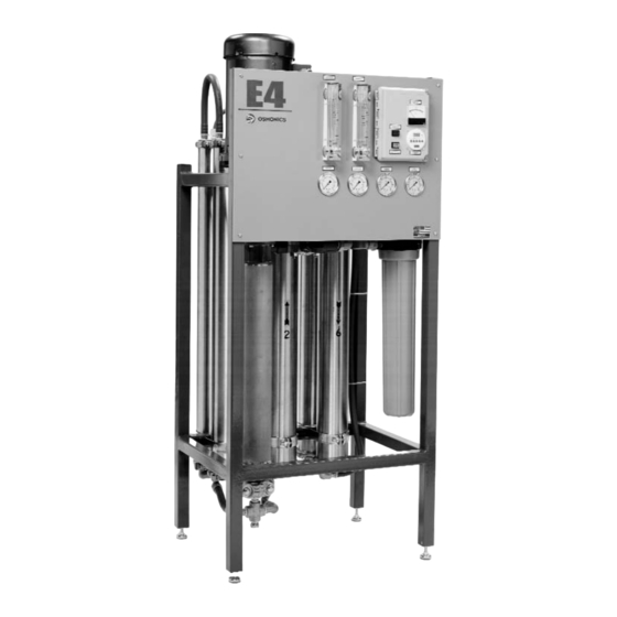
- Page 1 OSMONICS E4, E4LE, EZ4 SERIES WATER PURIFICATION MACHINES INSTALLATION, OPERATION, AND MAINTENANCE MANUAL GE Infrastructure Water & Process Technologies...
-
Page 3: Table Of Contents
2.15.4 Programming Twenty-Four Hour or Seven Day Schedules 2.15.5 Changing a Program 2.15.6 Deleting a Program 2.15.7 Troubleshooting the Autoflush Timer 2.16 Calibrating the Conductivity Probe INSTALLATION, OPERATION AND MAINTENANCE MANUAL E4, E4LE, AND EZ4 SERIES WATER PURIFICATION MACHINES TABLE OF CONTENTS Page... - Page 4 Setting-Up the Correct Time on the Autoflush Timer Programming the Timer Conductivity Probe Display Clean-In-Place Pump and Tank Hook-Up Table Description Connections E-Series Feed Water Requirements Pressure Correction Factors Flow Specifications for E4-Series Machines LIST OF FIGURES LIST OF TABLES Page...
-
Page 6: Installation
INSTALLATION Mounting the Unit When installing your new GE Infrastructure Water & Process Technologies reverse osmosis (RO) machine, allow at least 45-inches (114 cm) above the machine for mem- brane element removal and loading. If space is not available, the entire membrane element housing can be removed for membrane element change outs. -
Page 7: Installing Clean-In-Place Valves
Feed Water Requirements The following feed water requirements must be met before installing your new E4 machine to ensure quality permeate and extended membrane element life. Refer to Table 2.2 (E-Series Feed Water Requirements) for feed water information. -
Page 8: Transporting Pure Water (Permeate) To Point-Of-Use
Feed Water Requirements Temperature Inlet Pressure Chlorine (continuous feed) Operating pH Silt Density Index (SDI) American Standard for Testing Materials Transporting Pure Water (Permeate) to Point-of-Use The pure water, or permeate, is in an aggressive state and should only be transport- ed from the machine to the point-of-use in food grade flexible nylon, stainless steel (SS) tubing, or polyvinyl chloride (PVC) material for the inlet, permeate, and concen- trate piping sizes. -
Page 9: Pressure Correction Factors
THROUGH THE MEMBRANE ELEMENT WHEN THE MACHINE IS NOT IN OPERATION. REVERSE FLOW, WHEN THE MACHINE IS NOT IN OPERATION, CAN SEVERELY DAMAGE THE MEMBRANE ELEMENTS. Table 2.3 Pressure Correction Factors % LOSS OF PERMEATE FLOW E4/EZ4 E4LE E4/EZ4 0.95 0.90 0.80 0.70 0.60 0.50... -
Page 10: Electrical
Electrical This RO machine requires two supply voltages; the control voltage and the pump motor voltage. 2.8.1 Single-Phase Electrical The control voltage can be connected to either a 115 VAC, 60 Hertz or 220 VAC, 50 Hertz single-phase power supply. The RO control circuit should always be installed on at least a 15 Amp, single-phase dedi- cated circuit. -
Page 11: Machine Control
Allen Bradley Motor Starter Machine Control 2.9.1 Economy Model To remotely control the Economy Model (ECN) with float switches and/or pre- treatment lockout, remove the jumper between terminals 4 and 5 and wire in the float switches or pretreatment components in series. After all field wiring is complete and complies with local and national electrical codes, move onto Section 2.10 (Pretreatment for Water Purification). -
Page 12: Pretreatment For Water Purification
and complies with local and national electrical codes, move onto Section 2.10 (Pretreatment for Water Purification). NOTE: External control contacts are normally closed, dry contacts. 2.10 Pretreatment for Water Purification A water analysis of your feed water should have been performed, as part of the plan- ning and engineering that went into developing your RO system. - Page 13 While you are doing these valve adjustments, to obtain correct flows and pressures, observe the primary or pump pressure. The pump pressure, while adjusting the orifices, should never operate outside of these ranges: E4-Series Range: EZ4/E4LE-Series Range: 220 psi (15.2 bar) at 77°F (25°C) 115 psi (7.9 bar) at 77°F (25°C)
-
Page 14: Temperature Correction Factors
The concentrate valve is drilled, and when completely closed the machine is running at the correct concentrate flow for a 75% recovery (Table 2.4, Flow Specifications for E4-Series Machines). If the temperature of the inlet feed water is not 77°F (25°C) use the Temperature Correction Factor Table (Technote 113). -
Page 15: Recovery
5.8/11.6 Concentrate 5.8/11.6 Rate (50%) Concentrate 1.9/0.5 Rate (75%) Feed Rate 11.5/3.0 (50%) Feed Rate 7.7/2.0 (75%) Table 2.4 Flow Specifications for E4-Series Machines 4400 6600 50-75% 50-75% LPM/GPM LPM/GPM LPM/GPM 11.6/3.06 17.3/4.6 11.6/3.06 17.3/4.6 3.9/1.0 5.8/1.5 23.2/6.1 34.7/9.2 46.2/12.2 15.4/4.1... -
Page 16: Autoflush Timer
2.15 Autoflush Timer 2.15.1 Programming the Autoflush Timer The Autoflush timer clock operates and displays in real time, but the Autoflush feature will only work when the RO machine is operating. When the machine is operating in the Autoflush Mode, the total flow through the machine is increased. -
Page 17: Programming The Autoflush Timer Clock
STEPS While holding down the Clock Key ( the current minute. While holding down the Clock Key ( the current minute. While holding down the Clock Key ( the current minute. NOTE: If the h and m keys are held down for longer than 2 seconds, the numbers will advance rapidly. -
Page 18: Programming Twenty-Four Hour Or Seven Day Schedules
2.15.4 Programming Twenty-Four Hour or Seven Day Schedules NOTE: It is helpful to write out the program schedules before programming the time. Example: Figure 2.3 Programming the Timer 2.15.5 Changing a Program Select the program to be changed with the Prog. Key. A new set of days may be selected with the Day Key just as in the initial programming. -
Page 19: Troubleshooting The Autoflush Timer
2.15.7 Troubleshooting the Autoflush Timer PROBLEM: Days are flashing, pressing any Key does nothing except “Hand” Key turns output ON and OFF. SOLUTION: Time of Day and Day of Week have not been set. See Section 2.15.3 (Setting-Up the Autoflush Timer Clock). PROBLEM: Time of day was set while holding the Clock Key down, but days are still flashing. -
Page 20: Calibrating The Conductivity Probe
Calibrate the meter by adjusting the CAL adjustment screw until the Liquid Crystal Display (LCD) display reads 13 mS of the solution. The meter is now calibrated NOTE: The alarm function on the conductivity meter is not used on E4/EZ4/E4LE- Series machines. Conductivity Probe Display Figure 2.4... -
Page 21: Operation And Maintenance
Flush the RO machine daily. 2.17.1 Daily Flushing for the Economy Model If your E4-Series machine is an ECN Model it needs to be manually flushed daily. The DLX E4-Series machine is equipped with an Autoflush Timer (Section 2.15, Autoflush Timer). A daily manual flush must be performed. To flush the machine: With the machine running, open the concentrate valve 1/2 - 3/4 turn. -
Page 22: Pre-Filter Cartridge
2.19 Membrane Element Cleaning GE recommends that you clean your RO every quarter, depending on the quality of your feed water. Cleaning of the membrane elements is vital because contaminants can build up on the membrane element surfaces, reducing the permeate flow rate and affecting the quality of the permeate. -
Page 23: Clean-In-Place Pump And Tank Hook-Up
The size of the CIP container should be a minimum of three times the permeate rate. CAUTION GE recommends the use of a CIP or booster pump to provide the proper feed water pressure and quantity to the RO machine during cleaning. -
Page 24: Suction Cleaning
You are now ready for normal oper- ation. 2.20 Suction Cleaning GE does not recommend the suction cleaning method to clean the E4-Series RO machine. If using suction cleaning, reference cleaning with a CIP pump above (Section 2.19.2, Procedure to Clean with a CIP Pump). STEPS Arrange the RO and the CIP container in a closed loop situation with the cleaning solution, reference Section 2.19 (Membrane Element Cleaning). -
Page 25: Changing Out Membrane Elements
NOTE: After suction cleaning cycle is complete, reopen inlet water and flush machine to drain for twenty minutes. After permeate quality is verified as good, return machine to normal opera- tion mode. 2.21 Changing Out Membrane Elements CAUTION: Replacement membrane elements are shipped from the factory in a plastic bag with a small amount of bactericide solution to prevent bio- logical growth. - Page 26 Reattach the housing clamp and tighten. Next reconnect the permeate and concentrate lines. The machine is ready for start-up.
-
Page 27: Troubleshooting
Many of these problems can be easily corrected by the operator, however, for those that persist or are not understood, you should contact the GE Customer Support Center. Have the following information available when calling the Customer Support Center:... - Page 28 T R O U B L E S H O O T I N G G U I D E PROBLEM Low Operating Pump rotating backwards (continued) (three-phase power only) Insufficient electrical power Pump not operating correctly Low Permeate Flow Low operating pressure Rate Dirty or fouled membrane...
- Page 29 T R O U B L E S H O O T I N G G U I D E PROBLEM Low concentrate flow rate, normal or higher than normal pressure High operating pressure Recycle or concentrate valve Excessive pressure drop [over 50 psig (3.0 barg)] (high primary pressure - low final pressure)
- Page 30 Replace the damaged parts. Open the concentrate valve and flush. Test the water for pH, hard- ness, TDS and iron content. A water analysis should be sent to GE Infrastructure for review. Calibrate the monitor with a DS standard solution or check the readings with another conductivity meter.
- Page 31 No power to machine Check the fuses or circuit breakers, Motor and/or pump not See the pump instructions. Contact operating properly GE Infrastructure for possible repair Restart the machine by pushing the machine OFF tripped SOLUTION or position of float in the storage tank.
- Page 33 For more information call 952-933-2277 or 800-848-1750 in the U.S., or visit www.gewater.com. GE Infrastructure Water & Process Technologies North American Sales Euro/Africa Sales 5951 Clearwater Drive 230 rue Robert Schurman Minnetonka, MN ZA des Uselles 55343-8995 77350 Le Mée sur Seine...