Table of Contents
Advertisement
Advertisement
Table of Contents

Related Manuals for E-TON Beamer Scooter


Summary of Contents for E-TON Beamer Scooter
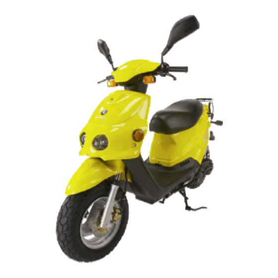
- Page 1 E-TON Beamer Scooter OWNER’S MANUAL...
-
Page 2: Important Notices
This manual was designed to provide you with the basic understanding of the structure, function, operation and maintenance of the Beamer Scooter. By following the instructions in this manual, you will be able to maintain the performance and prolong the service life of your Beamer Scooter. -
Page 3: Table Of Contents
Table of Contents Vehicle identification number location Controls, switches and feature locations Control feature operations Engine stop switch Turn Signal Switch Horn Button Head Light Control Switch Ignition Switch Instrument Cluster Throttle Control Throttle Cable Adjustment Brake Systems Front and Rear brakes Front Hydraulic Brake Inspection Hydraulic Fluid Reservoir Purging the brake lines... -
Page 4: Vehicle Identification Number Location
Vehicle Identification Numbers Vehicle Identification Number (VIN) is Engine serial number is located on the located on the frame behind the foot left-hand side of the engine on the guard and is covered by a small plastic crankcase housing. cover plate which can be removed with a screwdriver. -
Page 5: Control Feature Operations
Control feature operations Horn Button The horn button is a yellow push switch, located below the turning signal lamp switch on the left-hand handlebar. Pressing in on the button will sound the audible horn signal. Releasing the button will silence the horn. Engine Stop Switch The stop switch is a red colored rocker switch located on the left-hand handlebar. -
Page 6: Ignition Switch
Instrument Cluster The instrument cluster provides you with operating conditions of your vehicle. To the left is the fuel gauge which indicates the fuel level in the fuel tank. When the needle reaches the red zone on the gauge, you are running low on fuel and the tank should be refilled. -
Page 7: Throttle Control
Throttle Cable Adjusting To adjust the throttle cable’s free play, slide the protective cover down the cable to expose the cable adjusting system. Loosen the locking nut and adjust the cable length by turning the adjusting collar. Check the free travel in the throttle hand grip until you have Throttle Control . -
Page 8: Front Hydraulic Brake Inspection
The fluid level should fill at least ¾ of site glass when the unit is setting on a level surface. Test the brakes by applying pressure to the brake lever and trying to push the unit forward. If the wheel rotates while the brakes are applied, check your fluid level and brake pads. -
Page 9: Purging The Brake Lines
the brake cable with a commercial cable Purging Brake Lines lubricant available through your dealer. For the hydraulic brake system to operate safely, the brake system must be purged of air in the lines and Test the rear brake by applying pressure to reservoir. -
Page 10: Fuel System
Fuel System or replace the seal if it becomes worn or torn. The seal must be in good condition to insure a proper seal of the cap to the tank to prevent fuel spills. DO NOT allow dirt or other debris to enter the tank when refueling. Replace the cap if damaged or if it will not seal to the tank. -
Page 11: Engine Oil
tank cover retaining screw and lifting the Engine Oil Your vehicle uses 2 cycle oil to lubricate the engine. The oil tank is located under the seat at the front of the unit. Oil is drawn from this tank by an oil injector pump when the engine is operating. -
Page 12: Spark Plug
The air filter box is located on the left side of Spark Plug the engine under the body cover. It is a black box about 6” square and is attached to the Replace the spark plug every 10,000 miles or if crankcase with two bolts and the carburetor by the plug should become damaged or fouled. -
Page 13: Electrical Battery
There is an inline fuse on the positive lead of Electrical Battery the battery to protect the wiring system from over loads. If your starter motor will not turn over and the battery is fully charged, check the inline fuse on the unit. Replace the fuse with a 7A fuse. -
Page 14: Beamer Break-In Procedure
11. Insure you are wearing proper Beamer Break-In clothing and protective gear, such as procedures helmet and hard soled shoes. Starting Procedure Your Beamer requires a break-In period just as with all other internal combustion engines. This The following procedure must be followed period allows the engine parts to seat and wear each time you start your Beamer. -
Page 15: Parking
passenger pedals. Always keep your feet on the It is not recommended to operate this vehicle footrests and your hands on the handlebar grips in slippery conditions such as on snow or ice while operating your Beamer. Doing so will give covered roads. -
Page 16: Specifications
Beamer Scooter Specifications Beamer (Model - PN2) Engine Type Two cycle air cooled oil injected Displacement 49.3cc φ40.0 * 39.2mm Bore / Stroke Compression 6.8 : 1 Power 5.2hp @ 7000rpm Beamer Scooter Specifications (Continued) Transmission Type Automatic (C.V.T. V-Belt) -
Page 17: Maintenance Schedule
Spark Plug NGK (recommended) BPR7HS Nipendenso W22FRP-U Champion QL82YC Electrode Gap 0.6-0.7mm / 0.023" Max Driver & Passenger Weight 150kg / 330lbs. Subject to change without notice 10/01/203 Maintenance Schedule First week Notes Every 30 Days Every Year Replace Fuel & Vent Fuel Lines Lines every 2 years Inspect as part... - Page 18 Page 17...
- Page 19 ETON AMERICA, LLC. LIMITED VEHICLE WARRANTY ETON America warrants all new ETON vehicles sold by authorized Eton Dealers to be free from defects in materials and workmanship, subject to the following exclusions and limitations. New vehicles sold by an authorized dealer to original retail consumers are covered by this policy for a period of six (6) months from the date of delivery.
- Page 20 ETON AMERICA, LLC. LIMITED VEHICLE WARRANTY Scheduled maintenance service is the responsibility of the owner during and after the warranty period. In the event of a failure or required repair, the owner should take the vehicle to an authorized dealer for repair without undue delay and within a maximum of thirty (30) days of the occurrence of the problem.
-
Page 21: Owner's Notes
Owner’s Notes: Page 20... - Page 22 Owner’s Notes: Page 21...
- Page 23 Owner’s Notes: Page 22...
- Page 24 Page 23...