Table of Contents
Advertisement
Advertisement
Table of Contents
Troubleshooting

Related Manuals for MULTIQUIP DA7000SS


Summary of Contents for MULTIQUIP DA7000SS
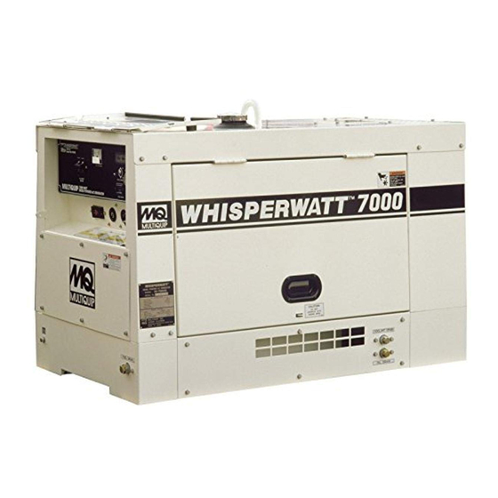
- Page 1 OPERATION AND PARTS MANUAL MODELS DA7000SS-DA7000SSA DA700SSW-DA7000WGH PORTABLE GENERATORS (KUBOTA Z482 SERIES DIESEL ENGINES) Revision #5 (01/20/11) To fi nd the latest revision of this publication, visit our website at: www.multiquip.com THIS MANUAL MUST ACCOMPANY THE EQUIPMENT AT ALL TIMES.
-
Page 2: Proposition 65 Warning
PROPOSITION 65 WARNING Diesel engine exhaust and some of PAGE 2 — DA7000 SERIES GENERATORS• OPERATION AND PARTS MANUAL — REV. #5 (01/20/11) -
Page 3: Reporting Safety Defects
If you believe that your vehicle has a defect that could cause a crash or could cause injury or death, you should immediately inform the National Highway Traffic Safety Administration (NHTSA) in addition to notifying Multiquip at 1-800-421-1244. If NHTSA receives similar complaints, it may open an investigation, and if it finds that a safety defect exists in a group of vehicles, it may order a recall and remedy campaign. -
Page 4: Table Of Contents
TABLE OF CONTENTS KUBOTA Z482-EB/E2B/E3B Die- DA7000 SERIES GENERATOR sel Engines Proposition 65 Warning ..........2 Reporting Safety Defects ..........3 Crankcase Assembly ..........88-89 Table Of Contents ............4 Oil Pump Assembly ..........90-91 Parts Ordering Procedures ..........5 Oil Pan Assembly ........... -
Page 5: Parts Ordering Procedures
, 2006 Order via Internet (Dealers Only) Best Deal! If you have an MQ Account, to obtain a Username Order parts on-line using Multiquip’s SmartEquip website! and Password, E-mail us at: parts@multiquip. ■ View Parts Diagrams com. ■ Order Parts To obtain an MQ Account, contact your ■... -
Page 6: Safety Information
SAFETY INFORMATION Do not operate or service the equipment before reading the Potential hazards associated with the operation of this entire manual. Safety precautions should be followed at all equipment will be referenced with hazard symbols which times when operating this equipment. Failure to read and may appear throughout this manual in conjunction with understand the safety messages and operating instructions safety messages. - Page 7 SAFETY INFORMATION NEVER use accessories or attachments that are not GENERAL SAFETY recommended by MQ Power for this equipment. Damage CAUTION to the equipment and/or injury to user may result. NEVER operate this equipment without proper protective ALWAYS know the location of the nearest clothing, shatterproof glasses, respiratory protection, fi...
- Page 8 SAFETY INFORMATION ENGINE SAFETY NOTICE NEVER run engine without an air fi lter or with a dirty air DANGER fi lter. Severe engine damage may occur. Service air fi lter The engine fuel exhaust gases contain poisonous carbon frequently to prevent engine malfunction.
- Page 9 SAFETY INFORMATION Make sure the hitch and coupling of the towing vehicle FUEL SAFETY are rated equal to, or greater than the trailer “gross DANGER vehicle weight rating.” DO NOT start the engine near spilled fuel or combustible ...
- Page 10 SAFETY INFORMATION Make sure power cables are securely connected to the ELECTRICAL SAFETY generator’s output receptacles. Incorrect connections DANGER may cause electrical shock and damage to the generator. DO NOT touch output terminals during operation. Contact with output terminals NOTICE during operation can cause electrocution, ...
- Page 11 SAFETY INFORMATION BATTERY SAFETY ENVIRONMENTAL SAFETY DANGER NOTICE DO NOT drop the battery. There is a possibility that the Dispose of hazardous waste properly. battery will explode. Examples of potentially hazardous waste are used motor oil, fuel and fuel fi lters. ...
-
Page 12: Specifi Cations (Generator)
Dry Net Weight 526 lbs. (239 kg) NOTICE In keeping with Multiquip's policy of constantly improving its products, the specifi cations quoted herein are subject to change without prior notice. PAGE 12 — DA7000 SERIES GENERATORS• OPERATION AND PARTS MANUAL — REV. #5 (01/20/11) -
Page 13: Specifi Cations (Engine)
SPECIFICATIONS (ENGINE) Table 2. Specifi cations (Engine) Kubota Engine Model Z482-EB Z482-E2B-DGDE-2 Z482-E3B-DGDE-2 Tier Gen. Enclosure Color Orange Orange/White White Type Vertical, water-cooled, 4-cycle diesel engine 2.64 in. X 2.68 in. Bore X Stroke (67 mm x 68 mm.) Displacement 29.23 cu.-in. -
Page 14: Dimensions
DIMENSIONS Figure 1. Dimensions PAGE 14 — DA7000 SERIES GENERATORS• OPERATION AND PARTS MANUAL — REV. #5 (01/20/11) - Page 15 NOTE DA7000 SERIES GENERATORS • OPERATION AND PARTS MANUAL — REV. #5 (01/20/11) — PAGE 15...
-
Page 16: Installation
INSTALLATION CONNECTING THE GROUND The nut and ground terminal on the generator should always be used to connect the generator to a suitable ground. The ground cable should be #8 size wire minimum. At the generator, connect the terminal of the ground cable between the lock washer and the nut (Figure 2) and tighten the nut fully. - Page 17 INSTALLATION OUTDOOR INSTALLATION GENERATOR GROUNDING If possible install the generator in a area that is free of To guard against electrical shock and possible damage to debris, bystanders, and overhead obstructions. Make sure the equipment, it is important to provide a good EARTH the generator is on secure level ground so that it cannot ground.
-
Page 18: General Information
This unit is equipped with a protective device that detects Generator low oil pressure. If the lubricating oil pressure of this unit The Multiquip DA7000 Series generators are 6.0 kW should become abnormally low, the protective device will (continuous output), 7.0 kW (max output) A.C. generators automatically stop the engine. -
Page 19: Components (Generator)
COMPONENTS (GENERATOR) Figure 3. Generator Components 1. Fuel Gauge — Indicates the amount of fuel in the 10. Automatic Speed Control Solenoid — Automatically fuel tank. regulates engine speed. 2. Air Outlet Exhaust — Allows engine exhaust to exit 11. Battery Terminals — Connect these terminals to the the generator into the open air. -
Page 20: Components (Generator)
(low/high RPM's). To prevent damage to the generator or power tools turn the generator OFF and consult your authorized Multiquip service dealer. 26. Hour Meter — Indicates number of hours machine has been in use or hours engine was run. -
Page 21: Components (Engine)
COMPONENTS (ENGINE) Figure 5. Kubota Z482 Series INITIAL SERVICING 8. Cooling Fan Blades — Make sure cooling fan blades The engine (Figure 5) must be checked for proper are not bent or broken. A damaged fan blade can cause lubrication and fi lled with fuel prior to operation. Refer to the engine to run hot and overheat. -
Page 22: Load Applications
LOAD APPLICATIONS Single Phase Load — 60 Hz To determine the running wattage for your load, multiply the running wattage as indicated by steps 1, 2, and 3 below: Always be sure to check the nameplate on the generators 1. INCANDESCENT LOADS and equipment to insure the wattage, amperage and Lights, heaters and similar appliances. -
Page 23: Inspection/Setup
INSPECTION/SETUP GENERAL INSPECTION PRIOR TO OPERATION NOTICE Ground Power Tools Double-insulated power tools and small appliances have specially insulated housings that eliminate the When using power tools or electrical equipment requireing need for a ground. These types of double-insulated AC power from the generator, make sure power tool cord power cords are designed so that no part of the device has a ground pin or is double insulated as shown in Figure 6. -
Page 24: Inspection/Setup
INSPECTION/SETUP Before Starting 4. If the oil level is low, remove the oil fi ller cap (Figure 9) and fi ll to a safe operating level (max) as indicated by 1. Read safety instructions at the beginning of manual. the dipstick. Fill with recommended type oil as listed in Table 5. - Page 25 INSPECTION/SETUP NOTICE NOTICE When refueling, be sure to use a strainer for fi ltration. When adding engine oil DO NOT overfi ll. DO NOT top-off fuel. DO NOT fi ll the tank beyond capacity. Wipe up any spilled fuel immediately! Fuel Check Coolant (Antifreeze) Fill the fuel tank with #2 diesel fuel.
- Page 26 INSPECTION/SETUP BATTERY NOTICE This unit is of negative ground DO NOT connect in reverse. When the antifreeze is mixed with water, the antifreeze Always maintain battery fl uid level between the specifi ed mixing ratio must be less than 50%. marks.
- Page 27 INSPECTION/SETUP When connecting battery do the following: 1. NEVER connect the battery cables to the battery terminals when the Ignition Switch is in the START position. ALWAYS make sure that the Ignition Switch is in the OFF position when connecting the battery. 2.
-
Page 28: Operation
OPERATION Before Starting the Engine 3. NEVER start the engine with the main circuit breaker in the ON position. Always place circuit breaker (Figure 16) CAUTION in the OFF position before starting. The engine’s exhaust contains harmful emissions. ALWAYS have adequate ventilation when operating. Direct exhaust away from nearby personnel. - Page 29 OPERATION 2. Place GFCI circuit breaker (Figure 21) in the ON 4. If the engine does not start within 10 seconds after the position. key is turned to the START position, wait for about 30 seconds and repeat the procedure as described in step 4.
-
Page 30: Shutdown
OPERATION/SHUTDOWN 4. The CS-6369 receptacle is a dual voltage receptacle Stopping the Engine (Normal Shutdown) (120/240 volts). Using an external voltmeter as shown 1. Place main circuit breaker (Figure 25) in the OFF in Figure 23, verify that 120/240 VAC is present at the position. -
Page 31: Preparation For Long Term Storage
PREPARATION FOR LONG TERM STORAGE Generator Storage For storage of the generating set for over 30 days, the following is required: Run the engine until all the fuel is completely consumed. Drain the fuel tank completely, or add STA-BIL to the fuel ... -
Page 32: Maintenance
MAINTENANCE Use Table 8as a general maintenance guideline when servicing your engine. For more detail engine maintenance information, refer to the engine owner's manual supplied with your engine. Table 8. Engine Maintenance Schedule EVERY EVERY 8 FIRST EVERY 3 EVERY 6 EVERY DESCRIPTION 2 YEARS... - Page 33 MAINTENANCE Maintenance 2. Screw on new oil fi lter by hand until seal contacts the fi lter mounting base. Install drain bolt with sealing Perform the scheduled maintenance procedures as defi ned washer and hand tighten. by Table 8 and below: NOTICE Engine Oil When installing the oil fi...
- Page 34 MAINTENANCE Cleaning the Fuel Filter Radiator Every 100 hours: Clean fuel fi lter every 100 hours of Check Daily: Always check the level of the coolant in the operation or once a month to remove dust or water. radiator before starting the engine. Remove the radiator cap and verify that the coolant reaches top of radiator coils.
- Page 35 MAINTENANCE 2. Flush the radiator by running clean tap water through GENERATOR STORAGE radiator until signs of rust and dirt are removed. DO For long term storage of the generator the following is NOT clean radiator core with any objects, such as a recommended: screwdriver.
-
Page 36: Maintenance (Trailer)
MAINTENANCE (TRAILER) TRAILER MAINTENANCE Follow the steps below to disassemble the wheel hub and service the wheel bearings. See Figure II. The following trailer maintenance guidelines are intended BEARING WHEEL to assist the operator in preventive maintenance. Adjustable Channel SEAL COTTER BEARING Your trailer may be equipped with an adjustable channel... -
Page 37: Maintenance (Trailer)
MAINTENANCE (TRAILER) Leaf Suspension DANGER The leaf suspension springs and associated components NEVER crawl under the trailer unless it is on fi rm (Figure III) should be visually inspected every 6,000 miles and level ground and resting on properly placed and for signs of excessive wear, elongation of bolt holes, and secured jackstands. -
Page 38: Trailer Guidelines
TRAILER GUIDELINES Shift your automatic transmission into a lower gear for The following guidelines are intended to assist the operator in the operation and handling of a trailer. city driving. ALWAYS use lower gears for climbing and descending Safety precautions should be followed at all times when operating a trailer. - Page 39 TRAILER GUIDELINES DRIVING CONDITIONS for the use of your trailer. Again, be sure your hitch and tow vehicle are rated for the Gross Vehicle Weight Rating of When towing a trailer, you will have decreased acceleration, your trailer. increased stopping distance, and increased turning radius WARNING (which means you must make wider turns to keep from hitting curbs, vehicles, and anything else that is on the...
- Page 40 TRAILER GUIDELINES INOPERABLE BRAKES, LIGHTS OR MIRRORS Drive slowly at fi rst, 5 mph or so, and turn the wheel to get the feel of how the tow vehicle and trailer combination Be sure that the brakes and all of the lights on your trailer responds.
- Page 41 TRAILER GUIDELINES To determine the “empty” or “net” weight of your trailer, weigh it on an axle scale. To fi nd the weight of the trailer using an axle scale, you must know the axle weights of your tow vehicle without the trailer coupled. Some of the trailer weight will be transferred from the trailer to the tow vehicle axles, and an axle scale weighs all axles, including the tow vehicle axles.
- Page 42 TRAILER GUIDELINES SAFETY CHAINS Check the locking device that secures the coupler to the ball for proper operation. If the coupler connection comes loose, the safety chains If you see or feel evidence of wear, such as fl at spots, can keep the trailer attached to the tow vehicle.
- Page 43 TRAILER GUIDELINES Lower the trailer (Figure D) until the coupler fully engages WARNING the hitch ball. A worn, cracked or corroded hitch ball can fail while 2-INCH TRAILER towing and may result in death or serious injury. COUPLER VEHICLE Before coupling trailer, inspect the hitch ball for wear, corrosion and cracks.
- Page 44 TRAILER GUIDELINES Backup Lights (place tow vehicle gear shift in reverse). Attaching Safety Chain Turn Signals (activate tow vehicle directional signal Visually inspect the safety chains and hooks for wear or lever). damage. Replace worn or damaged safety chains and hooks before towing.
- Page 45 TRAILER GUIDELINES PINTLE HITCH COUPLER If you see or feel evidence of wear, such as fl at spots, deformations, pitting or corrosion, on the pintle hook or A pintle eye coupler (Figure F) connects to a pintle-hook coupler, immediately have your dealer inspect them to hitch that is located on or under the rear bumper of the tow determine the proper action to prevent possible failure of vehicle.
- Page 46 TRAILER GUIDELINES Raise the bottom surface of the coupler to be above the Lower the trailer so that its entire tongue weight is held top of the pintle hitch hook. Use the tongue jackstand by the hitch. to support the trailer tongue. Wood or concrete blocks ...
- Page 47 TRAILER GUIDELINES wrench, use a lug wrench (from your tow vehicle) and This certifi cation/VIN label will indicate the trailer’s Gross tighten the nuts as much as you can. Then have a service Vehicle Weight Rating (GVWR). This is the most weight garage or trailer dealer tighten the lug nuts to the proper the fully loaded trailer can weigh.
- Page 48 TRAILER GUIDELINES Step 2. along with other care and maintenance activities, can also: Determine the weight of the equipment being loaded on the tow vehicle. That weight may not safely exceed Improve vehicle handling. the available equipment load capacity. The trailer’s Tire ...
- Page 49 TRAILER GUIDELINES Next number: This two-digit number is the wheel or rim in the tire. In general, the greater the number of plies, the diameter in inches. If you change your wheel size, you more weight a tire can support. Tire manufacturers also will have to purchase new tires to match the new wheel must indicate the materials in the tire, which include steel, diameter.
- Page 50 TRAILER GUIDELINES Tires for light trucks have other markings besides those sidewall should not be repaired. Tires must be removed found on the sidewalls of passenger tires. from the rim to be properly inspected before being plugged and patched. LT: The “LT” indicates the tire is for light trucks or trailers. Replacing Worn or Damaged Tires ST: An “ST”...
- Page 51 TRAILER GUIDELINES Wheel Rims 3. Check to see if the lug nuts are tight after the fi rst 10, 25 and 50 miles of driving and before each tow If the trailer has been struck, or impacted, on or near the thereafter wheels, or if the trailer has struck a curb, inspect the rims for damage (i.e.
-
Page 52: Trailer Wiring Digram
TRAILER WIRING DIGRAM Figure 37. Trailer Wiring Diagram PAGE 52 — DA7000 SERIES GENERATORS• OPERATION AND PARTS MANUAL — REV. #5 (01/20/11) -
Page 53: Generator Wiring Digram
GENERATOR WIRING DIGRAM Figure 38. Generator Wiring Diagram (DA7000 SERIES) DA7000 SERIES GENERATORS • OPERATION AND PARTS MANUAL — REV. #5 (01/20/11) — PAGE 53... -
Page 54: Engine Wiring Digram
ENGINE WIRING DIGRAM Figure 39. Engine Wiring Diagram PAGE 54 — DA7000 SERIES GENERATORS• OPERATION AND PARTS MANUAL — REV. #5 (01/20/11) -
Page 55: Troubleshooting (Engine And Generator)
TROUBLESHOOTING (ENGINE AND GENERATOR) Table 9. Engine and Generator Troubleshooting SYMPTOM POSSIBLE PROBLEM SOLUTION Dead Battery? Replace Battery. Defective Starter Switch? Replace Switch. Engine fails to start and starter does not rotate. Defective Starter? Replace Starter. Fuse F5 Burned Out? Replace Fuse. -
Page 56: Troubleshooting (Engine And Generator)
TROUBLESHOOTING (ENGINE AND GENERATOR) Table 9. Engine and Generator Troubleshooting (Continued) SYMPTOM POSSIBLE PROBLEM SOLUTION Engine starts and "Idle Defective Engine Regulator? Replace Regulator. Control Switch" is in OFF position. Engine Defective Wiring? Repair or Replace Wiring. speed rises and battery discharges too soon. -
Page 57: Troubleshooting (Engine)
TROUBLESHOOTING (ENGINE) Table 10. Engine Troubleshooting SYMPTOM POSSIBLE PROBLEM SOLUTION No fuel? Replenish fuel. Air in the fuel system? Bleed system. Water in the fuel system? Remove water from fuel tank. Fuel pipe clogged? Clean fuel pipe. Fuel fi lter clogged? Clean or change fuel fi... -
Page 58: Troubleshooting (Engine)
TROUBLESHOOTING (ENGINE) Table 10. Engine Troubleshooting (Continued) SYMPTOM POSSIBLE PROBLEM SOLUTION Fuel fi lter clogged or dirty? Clean or change. Air cleaner clogged? Clean or change. Fuel leak due to loose injection pipe retaining Tighten nut. nut? Engine revolution is not Injection pump malfunctioning? Repair or replace. - Page 59 NOTES DA7000 SERIES GENERATORS • OPERATION AND PARTS MANUAL — REV. #5 (01/20/11) — PAGE 59...
-
Page 60: Explanation Of Code In Remarks Column
A blank entry generally indicates that the item is not sold assembly/kit that can be purchased, or is not available separately or is not sold by Multiquip. Other entries will for sale through Multiquip. be clarifi ed in the “Remarks” Column. -
Page 61: Suggested Spare Parts
SUGGESTED SPARE PARTS DA7000 SERIES GENERATORS WITH KUBOTA NOTICE Z482-EB/Z482-E2B/ Z482-E3B DIESEL ENGINES Part numbers on this Suggested Spare Parts list may supersede/replace the part numbers shown in the 1 to 3 units following parts lists. Qty. Description 5....1556211010 ..AIR FILTER 5....7000011221 ..AIR FILTER, ELEMENT 5....1523143560 ..FUEL FILTER 5....7000015241 ..OIL FILTER CARTRIDGE, Z482-EB/Z482-E2B ENGINES... -
Page 62: Nameplate And Decals Assembly
NAMEPLATE AND DECALS ASSY. OPERATING PROCEDURE CAUTION MULTIQUIP WhisperWatt CHECK DAILY AC Generator 1. Check the oil level. 2. Check the water level. Let the engine idle for more than 5 minutes 1. Maintain water/coolant level with the Idle Control switch in “ON” position. - Page 63 DECAL: CAUTION OIL LEVEL GAUGE B9505000304 DECAL: CAUTION OIL LEVEL GAUGE ....1....B90500030 — DA7000SSA 8700625504 DECAL: FUSE BOX A556200004 DECAL: MQ ............1....A56200000 A5562100003 DECAL: STRIPE MULTIQUIP ......1....A56210000 A5562100104 DECAL: STRIPE MQ .........1....A56210010 A5562100204 DECAL: STRIPE MQ .........1....A56210020 A5562100303 DECAL: STRIPE WHISPERWATT .....2....A56210030 A5562100404 DECAL: STRIPE ..........1....A56210040...
-
Page 64: Generator Assembly
GENERATOR ASSY. PAGE 64 — DA7000 SERIES GENERATORS• OPERATION AND PARTS MANUAL — REV. #5 (01/20/11) - Page 65 GENERATOR ASSY. PART NO. PART NAME QTY. REMARKS A5110100003 ROTOR ASSY............1....INCLUDES ITEMS W/# 1-1# A5116000103 FIELD ASSY. 1-2# 7871025004 RECTIFIER ASSY. 1-3# 042006304 BEARING 6304 DOU .........1....REPLACES 0071206304 1-4# A5113100002 1-5# 0171707033 1-6# 1991072004 SET WASHER FAN 1-7# 0012308020 HEX HEAD BOLT 011208025 HEX HEAD BOLT ..........5....REPLACES 0012308025...
-
Page 66: Control Panel Assy
CONTROL PANEL ASSY. PAGE 66 — DA7000 SERIES GENERATORS• OPERATION AND PARTS MANUAL — REV. #5 (01/20/11) -
Page 67: Control Panel Assembly
CONTROL PANEL ASSY. PART NO. PART NAME QTY. REMARKS A5225000303 CONTROL PANEL A5511302402 CONTROL PANEL ..........1....DA7000SSA 0021805020 MACHINE SCREW 0601800258 AC VOLTMETER, 120/240 0207003000 HEX NUT 0601807456 CIRCUIT BREAKER, KM52 265V 25A 4341817004 BRACKET CIRCUIT BREAKER 0021004016 MACHINE SCREW 0601830771 IDLE CONTROL SWITCH 1628663602 STARTER SWITCH ...........1....REPLACES 0602100077... -
Page 68: Electric Parts Assembly
ELECTRIC PARTS ASSY. PAGE 68 — DA7000 SERIES GENERATORS• OPERATION AND PARTS MANUAL — REV. #5 (01/20/11) - Page 69 ELECTRIC PARTS ASSY. PART NO. PART NAME QTY. REMARKS A5262500203 BRACKET ELECTRIC PARTS 0016906016 HEX HEAD BOLT 0601842463 RESISTOR, 30W 10 OHM 0027104012 MACHINE SCREW 0601823204 RECTIFIER, S5VB60 0027103020 MACHINE SCREW 0601823754 RELAY 0027105016 MACHINE SCREW 1569465990 LAMP TIMER .............1....REPLACES 0602201273 0017105016 HEX HEAD BOLT 1747260604...
-
Page 70: Engine And Radiator Assembly
ENGINE AND RADIATOR ASSY. PAGE 70 — DA7000 SERIES GENERATORS• OPERATION AND PARTS MANUAL — REV. #5 (01/20/11) -
Page 71: Notice
ENGINE AND RADIATOR ASSY. PART NO. PART NAME QTY. REMARKS A5925200004 ENGINE, Z482EB ......1 ..DA7000SS A5924200004 ENGINE, Z482E2BDGDE2 ..1 ..DA7000SS A5924200094 ENGINE, Z482E3BDGDE2 ..1 ..DA7000SSA 1980572531 FAN BELT ........1 ..REPLACES P/N 0602011477 7000015241 CARTRIDGE OIL FILTER .... 1 ..REPLACES P/N's 1584132430 AND 0602041271 1585332435 CARTRIDGE OIL FILTER .... - Page 72 ENGINE AND RADIATOR ASSY. PAGE 72 — DA7000 SERIES GENERATORS• OPERATION AND PARTS MANUAL — REV. #5 (01/20/11)
-
Page 73: Notice
ENGINE AND RADIATOR ASSY. PART NO. PART NAME QTY. REMARKS 0802011104 PLUG 0150000018 O-RING A P18 0016906016 HEX HEAD BOLT D2322400004 HOSE JOINT 0199900550 DRAIN HOSE 0199900700 DRAIN HOSE 0199900500 DRAIN HOSE .............1....DA7000SSA 0605515094 HOSE BAND, Ø12 0805010004 DRAIN JOINT 1552053004 JOINT BOLT 0602021190... -
Page 74: Battery Assembly
BATTERY ASSY. PAGE 74 — DA7000 SERIES GENERATORS• OPERATION AND PARTS MANUAL — REV. #5 (01/20/11) - Page 75 BATTERY ASSY. PART NO. PART NAME QTY. REMARKS 0167103820 BATTERY 1702202104 BATTERY SHEET D2345200004 BATTERY BAND 0805082704 BATTERY BOLT 0037806000 WING NUT 0040006000 WASHER, LOCK 0041206000 WASHER, FLAT 0602220310 TERMINAL ASSY. (POSITIVE) 0602220311 TERMINAL ASSY. (NEGATIVE) 0602220600 TERMINAL CAP DA7000 SERIES GENERATORS • OPERATION AND PARTS MANUAL — REV. #5 (01/20/11) — PAGE 75...
-
Page 76: Muffl Er Assembly
MUFFLER ASSY. PAGE 76 — DA7000 SERIES GENERATORS• OPERATION AND PARTS MANUAL — REV. #5 (01/20/11) - Page 77 MUFFLER ASSY. PART NO. PART NAME QTY. REMARKS D2332100003 MUFFLER 0016908020 HEX. HEAD BOLT D2335000003 EXHAUST PIPE 1526312371 GASKET ............1....REPLACES 1526312371 1502336004 GASKET 0207008000 HEX. NUT 0016908035 HEX. HEAD BOLT DA7000 SERIES GENERATORS • OPERATION AND PARTS MANUAL — REV. #5 (01/20/11) — PAGE 77...
-
Page 78: Fuel Tank Assy
FUEL TANK ASSY. PAGE 78 — DA7000 SERIES GENERATORS• OPERATION AND PARTS MANUAL — REV. #5 (01/20/11) -
Page 79: Fuel Tank Assembly
FUEL TANK ASSY. PART NO. PART NAME QTY. REMARKS D2365000013 FUEL TANK 0810105800 CAP, FUEL TANK 0810105900 FUEL FILTER 0602125033 FUEL GAUGE D2365200004 TANK BAND 0805003414 PAD, TANK BANK 0016906016 HEX. HEAD BOLT 0207308000 HEX. NUT D1490600104 RUBBER SEAL 1615511204 RUBBER SEAL B9312400004A RUBBER SEAL ........ -
Page 80: Oil Filter Retrofi T Assembly
OIL FILTER RETROFIT ASSY. 7KW AC Mod el DA-7 000S STO P HEA T IDLE CONT ROL AC VOLT MET AC CIRC UIT BRE AKE R STAR T HOUR METE R PART OF ENCLOSURE ENGINE PAGE 80 — DA7000 SERIES GENERATORS• OPERATION AND PARTS MANUAL — REV. #5 (01/20/11) - Page 81 OIL FILTER RETROFIT ASSY. PART NO. PART NAME QTY. REMARKS 148002003 ADAPTER FILTER 010601000 HOSE KIT 149149001 BRACKET ......... 1 ....INCLUDES ITEMS W/# BOLT ......... 4 ....NOT SOLD SEPARATELY LOCKWASHER ......4 ....NOT SOLD SEPARATELY DA7000NUT DA7000LOCKWASHER LOCKWASHER DA7000BOLT BOLT...
-
Page 82: Enclosure Assembly
ENCLOSURE ASSY. PAGE 82 — DA7000 SERIES GENERATORS• OPERATION AND PARTS MANUAL — REV. #5 (01/20/11) - Page 83 ENCLOSURE ASSY. PART NO. PART NAME QTY. REMARKS A5415000202 BASE ............1 ....SEE ORDER CODE CHART BELOW D2492100004 LINING D2415100004 FLOOR PANEL .........1 ....SEE ORDER CODE CHART BELOW 0016906016 HEX HEAD BOLT A5415600104 DUCT ............1 ....SEE ORDER CODE CHART BELOW 0016906016 HEX HEAD BOLT D2455200113 SPLASHER PANEL ........1 ....SEE ORDER CODE CHART BELOW...
- Page 84 ENCLOSURE ASSY. PAGE 84 — DA7000 SERIES GENERATORS• OPERATION AND PARTS MANUAL — REV. #5 (01/20/11)
- Page 85 ENCLOSURE ASSY. PART NO. PART NAME QTY. REMARKS A5465000102 ROOF PANEL, (ORANGE UNITS) A5465000112 ROOF PANEL, (WHITE UNITS) 0016906016 HEX HEAD BOLT 8432081004 COVER RADIATOR CAP ......1 ....SEE ORDER CODE CHART BELOW 0016906016 HEX HEAD BOLT D245500113 SIDE DOOR A5495400704 LINING D2455000013 SIDE DOOR ..........1 ....SEE ORDER CODE CHART BELOW...
-
Page 86: Rubber Seals Assembly
RUBBER SEALS ASSY. PAGE 86 — DA7000 SERIES GENERATORS• OPERATION AND PARTS MANUAL — REV. #5 (01/20/11) - Page 87 RUBBER SEALS ASSY. PART NO. PART NAME QTY. REMARKS 0229400470 RUBBER SEAL 0229400760 RUBBER SEAL 0222900325 RUBBER SEAL 0222900125 RUBBER SEAL 0222600100 RUBBER SEAL 0228300600 RUBBER SEAL 0228300200 RUBBER SEAL 0228300550 RUBBER SEAL 0227600130 RUBBER SEAL 0227600500 RUBBER SEAL DA7000 SERIES GENERATORS • OPERATION AND PARTS MANUAL — REV. #5 (01/20/11) — PAGE 87...
-
Page 88: Kubota Z482-Eb/E2B/E3B Die- Sel Engines Crankcase Assembly
KUBOTA Z482-EB/E2B/E3B ENGINE — CRANKCASE ASSY. PAGE 88 — DA7000 SERIES GENERATORS• OPERATION AND PARTS MANUAL — REV. #5 (01/20/11) - Page 89 KUBOTA Z482-EB/E2B/E3B ENGINE — CRANKCASE ASSY. CRANKCASE ASSY. PART NO. PART NAME QTY. REMARKS 1685301012 COMP. CRANKCASE, Z482-EB ......1....INCLUDES ITEMS W/$ 1685301017 COMP. CRANKCASE, Z482-E2B ......1....INCLUDES ITEMS W/# 1685301019 COMP. CRANKCASE, Z482-E3B ......1....INCLUDES ITEMS W/% 020$#% 1685196260 CAP, SEALING 030$#% 1685196270 CAP, SEALING 040$#% 1545196270 CAP, SEALING...
-
Page 90: Oil Pump Assembly
KUBOTA Z482-EB/E2B/E3B ENGINE — OIL PUMP ASSY. PAGE 90 — DA7000 SERIES GENERATORS• OPERATION AND PARTS MANUAL — REV. #5 (01/20/11) - Page 91 KUBOTA Z482-EB/E2B/E3B ENGINE — OIL PUMP ASSY. OIL PUMP ASSY. PART NO. PART NAME QTY. REMARKS 1685135010 OIL PUMP ASSY..........1....Z482-EB 1685135012 OIL PUMP ASSY..........1....Z482-E2B AND Z482-E3B 1685135152 GASKET, OIL PUMP NA 1584191050 BOLT 1584135660 GEAR, OIL PUMP DRIVE 0571200408 KEY, FEATHER 0278350100...
-
Page 92: Oil Pan Assembly
KUBOTA Z482-EB/E2B/E3B ENGINE — OIL PAN ASSY. PAGE 92 — DA7000 SERIES GENERATORS• OPERATION AND PARTS MANUAL — REV. #5 (01/20/11) - Page 93 KUBOTA Z482-EB/E2B/E3B ENGINE — OIL PAN ASSY. OIL PAN ASSY. PART NO. PART NAME QTY. REMARKS 1756101505 COMP. OIL PAN 0112360814 BOLT 0102350612 BOLT ..............14....Z482-EB AND Z482-E2B 0102350614 BOLT ..............14....Z482-E3B 1654133750 PLUG, DRAIN 1545196670 GASKET 1685132110 FILTER, OIL 0481400160 O-RING DA7000 SERIES GENERATORS •...
-
Page 94: Cylinder Head Assembly
KUBOTA Z482-EB/E2B/E3B ENG. — CYLINDER HEAD ASSY. PAGE 94 — DA7000 SERIES GENERATORS• OPERATION AND PARTS MANUAL — REV. #5 (01/20/11) - Page 95 KUBOTA Z482-EB/E2B/E3B ENG. — CYLINDER HEAD ASSY. CYLINDER HEAD ASSY. PART NO. PART NAME QTY. REMARKS 1522101750 HOOK, ENGINE 0112360816 BOLT ..............2....Z482-EB 0112350816 BOLT ..............2....Z482-E2B AND Z482-E3B 1685503042 COMP. CYLINDER HEAD, Z482-EB ....1....INCLUDES ITEMS W/# 1G95703023 COMP. CYLINDER HEAD, Z482-E2B ....1....INCLUDES ITEMS W/% 1G68903040 COMP.
-
Page 96: Gear Case Assembly
KUBOTA Z482-EB/E2B/E3B ENGINE — GEAR CASE ASSY. PAGE 96 — DA7000 SERIES GENERATORS• OPERATION AND PARTS MANUAL — REV. #5 (01/20/11) - Page 97 KUBOTA Z482-EB/E2B/E3B ENGINE — GEAR CASE ASSY. GEAR CASE ASSY. PART NO. PART NAME QTY. REMARKS 1687504024 COMP. CASE, GEAR, Z482EB, Z482E2B ..1....INCLUDES ITEMS W/# 1E05104024 COMP. CASE, GEAR, Z482E3B ......1....INCLUDES ITEMS W/% 020#% 1685196010 PLUG ..............2....Z482EB 020#% 1552196030 PLUG ..............2....Z482-E2B AND Z482-E3B 030#% 1584156280 PIN, START SPRING 0481406130...
-
Page 98: Head Cover Assembly
KUBOTA Z482-EB/E2B/E3B ENGINE — HEAD COVER ASSY. PAGE 98 — DA7000 SERIES GENERATORS• OPERATION AND PARTS MANUAL — REV. #5 (01/20/11) - Page 99 KUBOTA Z482-EB/E2B/E3B ENGINE — HEAD COVER ASSY. HEAD COVER ASSY. (Z482-EB) PART NO. PART NAME QTY. REMARKS 1588105550 JOINT, BREATHER PIPE 1584105140 PLATE, BREATHER ELEMENT 1584105150 PLATE, BREATHER ELEMENT 1584105670 ELEMENT, BREATHER 1584105370 OIL SHIELD, BREATHER 1686193310 SCREW 1584705512 PIPE, BREATHER 1584105590 CLAMP, PIPE 0211450080...
- Page 100 KUBOTA Z482-EB/E2B/E3B ENGINE — HEAD COVER ASSY. PAGE 100 — DA7000 SERIES GENERATORS• OPERATION AND PARTS MANUAL — REV. #5 (01/20/11)
- Page 101 KUBOTA Z482-EB/E2B/E3B ENGINE — HEAD COVER ASSY. HEAD COVER ASSY. (Z482-E2B/Z482-E3B) PART NO. PART NAME QTY. REMARKS 1G95714503 COVER CYLINDER HEAD, Z482-E2B ....1....INCLUDES ITEMS W/# 1G95714504 COVER CYLINDER HEAD, Z482-E3B ....1....INCLUDES ITEMS W/% 020# 1624173370 PIPE, WATER RETURN 030# 1G91105203 COMP.
-
Page 102: Oil Filter Assembly
KUBOTA Z482-EB/E2B/E3B ENGINE — OIL FILTER ASSY. PAGE 102 — DA7000 SERIES GENERATORS• OPERATION AND PARTS MANUAL — REV. #5 (01/20/11) - Page 103 KUBOTA Z482-EB/E2B/E3B ENGINE — OIL FILTER ASSY. OIL FILTER ASSY. PART NO. PART NAME QTY. REMARKS 7000015241 CARTRIDGE, OIL FILTER, Z482-EB ....1....REPLACES P/N 1585399170 1585332430 CARTRIDGE, OIL FILTER .........1....Z482-E2B AND Z482-E3B 1584194010 WASHER, FLAT 1524132290 JOINT, PIPE DA7000 SERIES GENERATORS • OPERATION AND PARTS MANUAL — REV. #5 (01/20/11) — PAGE 103...
-
Page 104: Dipstick And Guide Assembly
KUBOTA Z482-EB/E2B/E3B ENG. — DIPSTICK AND GUIDE ASSY. PAGE 104 — DA7000 SERIES GENERATORS• OPERATION AND PARTS MANUAL — REV. #5 (01/20/11) - Page 105 KUBOTA Z482-EB/E2B/E3B ENG. — DIPSTICK AND GUIDE ASSY. DIPSTICK AND GUIDE ASSY. PART NO. PART NAME QTY. REMARKS 1685136410 GAUGE, OIL ............1....Z482-EB 1G30436410 GAUGE, OIL ............1....Z482-E2B AND Z482-E3B 1745636420 GUIDE, OIL GAUGE ..........1....Z482-E2B AND Z482-E3B DA7000 SERIES GENERATORS • OPERATION AND PARTS MANUAL — REV. #5 (01/20/11) — PAGE 105...
-
Page 106: Main Bearing Case Assembly
KUBOTA Z482-EB/E2B/E3B ENG. — MAIN BEARING CASE ASSY. PAGE 106 — DA7000 SERIES GENERATORS• OPERATION AND PARTS MANUAL — REV. #5 (01/20/11) - Page 107 KUBOTA Z482-EB/E2B/E3B ENG. — MAIN BEARING CASE ASSY. MAIN BEARING CASE ASSY. PART NO. PART NAME QTY. REMARKS 1685104092 ASSY. CASE, MAIN BEARING, Z482-EB/E2B ..1....INCLUDES ITEMS W/@ 1685107090 ASSY. CASE, MAIN BEARING, Z482-E3B ..1....INCLUDES ITEMS W/$ 015@$ 1686123480 METAL, CRANKSHAFT M 020@$ 1584104540 BOLT, BEARING CASE 1585204360...
-
Page 108: Camshaft And Idle Gear Assembly
KUBOTA Z482-EB/E2B/E3B ENGINE — CAMSHAFT AND IDLE GEAR ASSY. PAGE 108 — DA7000 SERIES GENERATORS• OPERATION AND PARTS MANUAL — REV. #5 (01/20/11) - Page 109 KUBOTA Z482-EB/E2B/E3B ENGINE — CAMSHAFT AND IDLE GEAR ASSY. CAMSHAFT AND IDLE GEAR SHAFT ASSY. PART NO. PART NAME QTY. REMARKS 1685115550 TAPPET .............4....Z482-EB 1685115552 TAPPET .............4....Z482-E2B AND Z482-E3B 1685115110 PUSH ROD 1584116015 CAMSHAFT ASSY..........1....INCLUDES ITEMS W/% 1584116019 CAMSHAFT ASSY..........1....INCLUDES ITEMS W/$ 040$ 1552193610 SCREW, SET .............1....Z482-EB...
-
Page 110: Piston And Crankshaft Assembly
KUBOTA Z482-EB/E2B/E3B ENG. — PISTON AND CRANKSHAFT ASSY. PAGE 110 — DA7000 SERIES GENERATORS• OPERATION AND PARTS MANUAL — REV. #5 (01/20/11) - Page 111 KUBOTA Z482-EB/E2B/E3B ENG. — PISTON AND CRANKSHAFT ASSY. PISTON AND CRANKSHAFT ASSY. PART NO. PART NAME QTY. REMARKS 1685121112 PISTON STD ...........2....Z482-EB AND Z482-E2B 1685121114 PISTON STD ...........2....Z482-E3B 1685121900 PISTON +0.25MM ..........2....Z482-EB AND Z482-E2B 1685121903 PISTON +0.25MM ..........2....Z482-E3B 1685321050 ASSY. PISTON RING STD 1685321090 ASSY.
-
Page 112: Flywheel Assembly
KUBOTA Z482-EB/E2B/E3B ENGINE — FLYWHEEL ASSY. PAGE 112 — DA7000 SERIES GENERATORS• OPERATION AND PARTS MANUAL — REV. #5 (01/20/11) - Page 113 KUBOTA Z482-EB/E2B/E3B ENGINE — FLYWHEEL ASSY. FLYWHEEL ASSY. PART NO. PART NAME QTY. REMARKS 1685125010 COMP. FLYWHEEL, Z482-EB ......1....INCLUDES ITEMS W/# 1685125015 COMP. FLYWHEEL, Z482-E2B/E3B ....1....INCLUDES ITEMS W/% 020# 1685163820 GEAR, RING, Z482-EB 020% 1685163822 GEAR, RING, Z482-E2B AND Z482-E3B 1585225160 BOLT, FLYWHEEL 1584704612...
-
Page 114: Fuel Camshaft And Gov. Shaft Assembly
KUBOTA Z482-EB/E2B/E3B ENG. — FUEL CAMSHAFT & GOV. SHAFT ASSY. PAGE 114 — DA7000 SERIES GENERATORS• OPERATION AND PARTS MANUAL — REV. #5 (01/20/11) - Page 115 KUBOTA Z482-EB/E2B/E3B ENG. — FUEL CAMSHAFT & GOV. SHAFT ASSY. FUEL CAMSHAFT AND GOVERNOR SHAFT ASSY. PART NO. PART NAME QTY. REMARKS 1685116020 CAMSHAFT ASSY., FUEL, Z482-EB/E2B ..1....INCLUDES ITEMS W/# 1685116023 CAMSHAFT ASSY., FUEL, Z482-E3B ....1....INCLUDES ITEMS W/$ 020# 1584116172 CAMSHAFT, FUEL 030# 0815306203...
-
Page 116: Engine Stop Lever Assembly
KUBOTA Z482-EB/E2B/E3B ENG. — ENG. STOP LEVER ASSY. PAGE 116 — DA7000 SERIES GENERATORS• OPERATION AND PARTS MANUAL — REV. #5 (01/20/11) - Page 117 KUBOTA Z482-EB/E2B/E3B ENG. — ENG. STOP LEVER ASSY. ENGINE STOP LEVER ASSY. PART NO. PART NAME QTY. REMARKS 1584154092 ASSY. APPARATUS, IDLE .........1....INCLUDES ITEMS W/# 020# 1584154100 ASSY. BOLT, ADJUSTING 030# 1526192020 040# 1584154220 NUT, CAP 050# 1502133660 GASKET 1584154270 1584154122 BOLT, ADJUSTING ..........1....Z482-EB 1584154123...
-
Page 118: Stop Solenoid Assembly
KUBOTA Z482-EB/E2B/E3B ENG. — STOP SOLENOID ASSY. PAGE 118 — DA7000 SERIES GENERATORS• OPERATION AND PARTS MANUAL — REV. #5 (01/20/11) - Page 119 KUBOTA Z482-EB/E2B/E3B ENG. — STOP SOLENOID ASSY. STOP SOLENOID ASSY. PART NO. PART NAME QTY. REMARKS 1685160010 SOLENOID, STOP ..........1....Z482-EB 1685160013 SOLENOID, STOP ..........1....Z482-E2B 1685160014 SOLENOID, STOP ..........1....Z482-E3B 0175450612 BOLT, FLANGE DA7000 SERIES GENERATORS • OPERATION AND PARTS MANUAL — REV. #5 (01/20/11) — PAGE 119...
-
Page 120: Injection Pump Assembly
KUBOTA Z482-EB/E2B/E3B ENG. — INJECTION PUMP ASSY. PAGE 120 — DA7000 SERIES GENERATORS• OPERATION AND PARTS MANUAL — REV. #5 (01/20/11) - Page 121 KUBOTA Z482-EB/E2B/E3B ENG. — INJECTION PUMP ASSY. INJECTION PUMP ASSY. PART NO. PART NAME QTY. REMARKS 1600151010 PUMP ASSY., INJECTION ........1....INCLUDES ITEMS W/% 1600152090 SHIM, INJECTION PUMP, 20 MM 1600152110 SHIM, INJECTION PUMP, 25 MM 1600152120 SHIM, INJECTION PUMP, 30 MM 1G68952160 SHIM, INJECTION PUMP, 35 MM .....1....Z482-E3B ONLY 1G68952200...
-
Page 122: Injection Pump Components Assembly
KUBOTA Z 482-EB ENGINE—INJECTION PUMP COMPONENTS ASSY. PAGE 122 — DA7000 SERIES GENERATORS• OPERATION AND PARTS MANUAL — REV. #5 (01/20/11) - Page 123 KUBOTA Z 482-EB ENGINE—INJECTION PUMP COMPONENTS ASSY. INJECTION PUMP COMPONENTS ASSY. PART NO. PART NAME QTY. REMARKS 1600151010 INJECTION PUMP ASSY., Z482-EB ....1....INCLUDES ITEMS W/# 1754851010 INJECTION PUMP ASSY., Z482-E2B/E3B ..1....INCLUDES ITEMS W/% 020# 1685151050 PLUNGER, PUMP, Z482-EB 020% 1754851050 PLUNGER, PUMP, Z482-E2B/E3B 030# 1584151030...
-
Page 124: Speed Control Plate Assembly
KUBOTA Z482-EB/E2B/E3B ENG. — SPEED CONTROL PLATE ASSY. PAGE 124 — DA7000 SERIES GENERATORS• OPERATION AND PARTS MANUAL — REV. #5 (01/20/11) - Page 125 KUBOTA Z482-EB/E2B/E3B ENG. — SPEED CONTROL PLATE ASSY. SPEED CONTROL PLATE ASSY. PART NO. PART NAME QTY. REMARKS 1584157110 PLATE, SPEED CONTROL .......1....Z482-EB 010% 1584157112 PLATE, SPEED CONTROL .......1....Z482-E2B AND Z482-E3B 1584157212 GASKET, CONTROL PLATE 0102350618 BOLT 0105350618 BOLT ..............2....Z482-EB AND Z482-E2B 1687191050 BOLT ..............2....Z482-E3B 1560196650...
-
Page 126: Nozzle Holder And Glow Assembly
KUBOTA Z482-EB/E2B/E3B ENG. — NOZZLE HOLDER AND GLOW ASSY. PAGE 126 — DA7000 SERIES GENERATORS• OPERATION AND PARTS MANUAL — REV. #5 (01/20/11) - Page 127 KUBOTA Z482-EB/E2B/E3B ENG. — NOZZLE HOLDER AND GLOW ASSY. NOZZLE HOLDER AND GLOW PLUG ASSY. PART NO. PART NAME QTY. REMARKS 1585242502 PIPE ASSY., OVER FLOW 1584142500 PIPE ASSY., OVER FLOW ........1....INCLUDES ITEMS W/# 025# 1584142520 PIPE, FUEL OVER FLOW 030# 1497142750 CLIP, PIPE...
-
Page 128: Nozzle Holder Assembly
KUBOTA Z482-EB/E2B/E3B ENGINE — NOZZLE HOLDER ASSY. PAGE 128 — DA7000 SERIES GENERATORS• OPERATION AND PARTS MANUAL — REV. #5 (01/20/11) - Page 129 KUBOTA Z482-EB/E2B/E3B ENGINE — NOZZLE HOLDER ASSY. NOZZLE HOLDER ASSY. PART NO. PART NAME QTY. REMARKS 1600153000 ASSY. HOLDER, NOZZLE ..........2 ....INCLUDES ITEMS W/ % 1584192030 1584153230 WASHER, ADJUSTING 1584153170 SPRING, NOZZLE 1584153350 PIECE, DISTANCE 1584153160 PUSH ROD 1647553280 NUT, NOZZLE 1584194040 WASHER...
-
Page 130: Fork Lever Assembly
KUBOTA Z482-EB/E2B/E3B ENGINE — FORK LEVER ASSY. PAGE 130 — DA7000 SERIES GENERATORS• OPERATION AND PARTS MANUAL — REV. #5 (01/20/11) - Page 131 KUBOTA Z482-EB/E2B/E3B ENGINE — FORK LEVER ASSY. FORK LEVER ASSY. PART NO. PART NAME QTY. REMARKS 1685156480 SPRING, START 1946156410 SPRING, GOVERNOR 1754856054 LEVER, FORK ASSY.........1....INCLUDES ITEMS/# LEVER, FORK COMP ........1....NOT SOLD SEPARATELY HOLDER, FORK LEVER ........1....NOT SOLD SEPARATELY 050# 1584156060 LEVER, FORK ASSY.
- Page 132 KUBOTA Z482-EB/E2B/E3B ENGINE — FUEL FILTER ASSY. PAGE 132 — DA7000 SERIES GENERATORS• OPERATION AND PARTS MANUAL — REV. #5 (01/20/11)
- Page 133 KUBOTA Z482-EB/E2B/E3B ENGINE — FUEL FILTER ASSY. FUEL FILTER ASSY. PART NO. PART NAME QTY. REMARKS 1553143010 FILTER, FUEL ASSY..........1....INCLUDES ITEMS W/$ .....................REPLACES P/N 1553143012 020$ 1553143110 COMP. BODY, COCK .........1....INCLUDES ITEMS W/# 030$# 1430143522 LEVER, COCK 040 $# 1430143820 SPRING, VALVE 050$# 1430143830 SCREW, SET...
-
Page 134: Fuel Pump Assembly
KUBOTA Z482-EB/E2B/E3B ENGINE—FUEL PUMP ASSY. PAGE 134 — DA7000 SERIES GENERATORS• OPERATION AND PARTS MANUAL — REV. #5 (01/20/11) - Page 135 KUBOTA Z482-EB/E2B/E3B ENGINE—FUEL PUMP ASSY. FUEL PUMP ASSY. PART NO. PART NAME QTY. REMARKS 1582152030 FUEL PUMP ASSY. 1626452140 GASKET, FUEL PUMP 0102350616 BOLT DA7000 SERIES GENERATORS • OPERATION AND PARTS MANUAL — REV. #5 (01/20/11) — PAGE 135...
-
Page 136: Dynamo And Pulley Assembly
KUBOTA Z482-EB/E2B/E3B ENGINE — DYNAMO & PULLEY ASSY. PAGE 136 — DA7000 SERIES GENERATORS• OPERATION AND PARTS MANUAL — REV. #5 (01/20/11) - Page 137 KUBOTA Z482-EB/E2B/E3B ENGINE — DYNAMO & PULLEY ASSY. DYNAMO AND PULLEY ASSY. PART NO. PART NAME QTY. REMARKS 1753164010 DYNAMO ASSY..........1....Z482-EB 1753164012 DYNAMO ASSY..........1....Z482-E2B AND Z482-E3B 1259964420 STAY, DYNAMO 0112350830 BOLT ..............1....Z482-EB 1687191030 BOLT ..............1....Z482-E2B AND Z482-E3B 0115350855 BOLT 0401360080 WASHER, FLAT...
-
Page 138: Dynamo Assembly
KUBOTA Z482-EB/E2B/E3B ENGINE — DYNAMO ASSY. PAGE 138 — DA7000 SERIES GENERATORS• OPERATION AND PARTS MANUAL — REV. #5 (01/20/11) - Page 139 KUBOTA Z482-EB/E2B/E3B ENGINE — DYNAMO ASSY. DYNAMO ASSY. PART NO. PART NAME QTY. REMARKS 1753164010 DYNAMO ASSY. , Z482-EB ...1 ......INCLUDES ITEMS W/% 1753164012 DYNAMO ASSY. , Z482-E2B/E3B ..1 ......INCLUDES ITEMS W/# 1553164122 COMP. FLYWHEEL, Z482-EB ..1 ......INCLUDES ITEMS W/+ 1553264120 COMP.
-
Page 140: Starter Assembly
KUBOTA Z482-EB/E2B/E3B ENGINE — STARTER ASSY. PAGE 140 — DA7000 SERIES GENERATORS• OPERATION AND PARTS MANUAL — REV. #5 (01/20/11) - Page 141 KUBOTA Z482-EB/E2B/E3B ENGINE — STARTER ASSY. STARTER ASSY. PART NO. PART NAME QTY. REMARKS 1983763010 STARTER ASSY. 12V, 0.8KW 0112350825 BOLT DA7000 SERIES GENERATORS • OPERATION AND PARTS MANUAL — REV. #5 (01/20/11) — PAGE 141...
-
Page 142: Starter Components Assembly
KUBOTA Z482-EB/E2B/E3B ENGINE — STARTER COMP. ASSY. PAGE 142 — DA7000 SERIES GENERATORS• OPERATION AND PARTS MANUAL — REV. #5 (01/20/11) - Page 143 KUBOTA Z482-EB/E2B/E3B ENGINE — STARTER COMP. ASSY. STARTER COMPONENTS ASSY. PART NO. PART NAME QTY. REMARKS 1983763010 STARTER ASSY..........1....INCLUDES ITEMS W/@ 020@ 1983763050 LEVER, DRIVE 030@ 1585263020 SWITCH, MAGNETIC 040@ 1983763030 FRAME, DRIVE END .........1....INCLUDES ITEMS W/# 050@# 1585263240 BUSH 060@ 1983763150...
-
Page 144: Oil Switch Assembly
KUBOTA Z482-EB ENGINE — OIL SWITCH ASSY. PAGE 144 — DA7000 SERIES GENERATORS• OPERATION AND PARTS MANUAL — REV. #5 (01/20/11) - Page 145 KUBOTA Z482-EB ENGINE — OIL SWITCH ASSY. OIL SWITCH ASSY. PART NO. PART NAME QTY. REMARKS 1584139010 SWITCH, OIL .............1....Z482-EB 1584139013 SWITCH, OIL .............1....Z482-E2B AND Z482-E3B 1584196020 PLUG ..............1....Z482-E2B AND Z482-E3B DA7000 SERIES GENERATORS • OPERATION AND PARTS MANUAL — REV. #5 (01/20/11) — PAGE 145...
-
Page 146: Water Flange And Thermostat Assembly
KUBOTA Z482-EB/E2B/E3B ENGINE — WATER FLANGE & THERM. ASSY. PAGE 146 — DA7000 SERIES GENERATORS• OPERATION AND PARTS MANUAL — REV. #5 (01/20/11) - Page 147 KUBOTA Z482-EB/E2B/E3B ENGINE — WATER FLANGE & THERM. ASSY. WATER FLANGE AND THERMOSTAT ASSY. PART NO. PART NAME QTY. REMARKS 1687572700 COMP. FLANGE, WATER, Z482-EB ....1....INCLUDES ITEMS W/% 1687572704 COMP. FLANGE, WATER, Z482-E2B/E3B ..1....INCLUDES ITEMS W/# 020%# 1624173370 PIPE, WATER RETURN 1584172922 GASKET, WATER FLANGE .......1....Z482-EB 1584172923...
-
Page 148: Water Pump Assembly
KUBOTA Z482-EB/E2B/E3B ENGINE — WATER PUMP ASSY. PAGE 148 — DA7000 SERIES GENERATORS• OPERATION AND PARTS MANUAL — REV. #5 (01/20/11) - Page 149 KUBOTA Z482-EB/E2B/E3B ENGINE — WATER PUMP ASSY. WATER PUMP ASSY. PART NO. PART NAME QTY. REMARKS 1988373030 WATER PUMP ASSY.........1....INCLUDES ITEMS W/@ 020@ 1585273520 FLANGE, WATER PUMP 030@ 1585273550 BEARING 040@ 1548173050 SEAL ASSY., MECHANICAL 050@ 1988373510 IMPELLER, WATER PUMP........1....Z482-EB AND Z482-E2B ONLY 060@ 1585273340 PIPE, WATER RETURN 1588173432...
-
Page 150: Water Pipe Assembly
KUBOTA Z482-EB/E2B/E3B ENGINE — WATER PIPE ASSY. PAGE 150 — DA7000 SERIES GENERATORS• OPERATION AND PARTS MANUAL — REV. #5 (01/20/11) - Page 151 KUBOTA Z482-EB/E2B/E3B ENGINE — WATER PIPE ASSY. WATER PIPE ASSY. PART NO. PART NAME QTY. REMARKS 1584172860 PIPE, WATER 1588172870 PIPE, WATER 1584191510 STUD 0275150060 NUT, FLANGE 0931889030 CLAMP, HOSE ...........2....Z482-EB 1584172960 BAND, PIPE ............2....Z482-E2B AND Z482-E3B DA7000 SERIES GENERATORS • OPERATION AND PARTS MANUAL — REV. #5 (01/20/11) — PAGE 151...
-
Page 152: Fan Assembly
KUBOTA Z482-EB/E2B/E3B ENGINE — FAN ASSY. PAGE 152 — DA7000 SERIES GENERATORS• OPERATION AND PARTS MANUAL — REV. #5 (01/20/11) - Page 153 KUBOTA Z482-EB/E2B/E3B ENGINE — FAN ASSY. FAN ASSY. PART NO. PART NAME QTY. REMARKS 1586774112 1584174250 PULLEY, FAN 0175450610 BOLT, FLANGE DA7000 SERIES GENERATORS • OPERATION AND PARTS MANUAL — REV. #5 (01/20/11) — PAGE 153...
-
Page 154: Valve And Rocker Arm Assembly
KUBOTA Z482-EB/E2B/E3B ENG. — VALVE AND ROCKER ARM ASSY. PAGE 154 — DA7000 SERIES GENERATORS• OPERATION AND PARTS MANUAL — REV. #5 (01/20/11) - Page 155 KUBOTA Z482-EB/E2B/E3B ENG. — VALVE AND ROCKER ARM ASSY. VALVE AND ROCKER ARM ASSY. PART NO. PART NAME QTY. REMARKS 1460113110 VALVE, INLET 1460113120 VALVE, EXHAUST 1460113240 SPRING, VALVE 1460113330 RETAINER, SPRING 1460113360 COLLET, VALVE SPRING SET 1685113280 CAP, VALVE 1584113150 SEAL, VALVE STEM 1584114263...
-
Page 156: Inlet Manifold Assembly
KUBOTA Z482-EB/E2B/E3B ENGINE — INLET MANIFOLD ASSY. PAGE 156 — DA7000 SERIES GENERATORS• OPERATION AND PARTS MANUAL — REV. #5 (01/20/11) - Page 157 KUBOTA Z482-EB/E2B/E3B ENGINE — INLET MANIFOLD ASSY. INLET MANIFOLD ASSY. PART NO. PART NAME QTY. REMARKS 1584111770 MANIFOLD, INLET ASSY., Z482-EB ....1....INCLUDES ITEMS W/% 010A 1G95711771 MANIFOLD, INLET ASSY., Z482-E2B/E3B ..1....INCLUDES ITEMS W/# 015# 1G96005550 PIPE BREATHER ..........1....Z482-E2B AND Z482-E3B 020%# 1584111820 GASKET, IN-MANIFOLD 0102350618...
-
Page 158: Exhaust Manifold Assembly
KUBOTA Z482-EB/E2B/E3B ENGINE — EXHAUST MANIFOLD ASSY. PAGE 158 — DA7000 SERIES GENERATORS• OPERATION AND PARTS MANUAL — REV. #5 (01/20/11) - Page 159 KUBOTA Z482-EB/E2B/E3B ENGINE — EXHAUST MANIFOLD ASSY. EXHAUST MANIFOLD ASSY. PART NO. PART NAME QTY. REMARKS 1584112313 MANIFOLD, EXHAUST 1584112360 GASKET 0175950616 BOLT, UBS 0151350618 STUD 0275650060 NUT, UBS 0151350822 STUD 1526312370 GASKET, MUFFLER DA7000 SERIES GENERATORS • OPERATION AND PARTS MANUAL — REV. #5 (01/20/11) — PAGE 159...
-
Page 160: Glow Plug/Lamp And Timer Assembly
KUBOTA Z482-EB/E2B/E3B ENG. — GLOW PLUG/LAMP AND TIMER ASSY. PAGE 160 — DA7000 SERIES GENERATORS• OPERATION AND PARTS MANUAL — REV. #5 (01/20/11) - Page 161 KUBOTA Z482-EB/E2B/E3B ENG. — GLOW PLUG/LAMP AND TIMER ASSY. GLOW PLUG/LAMP AND TIMER ASSY. PART NO. PART NAME QTY. REMARKS 1569465990 TIMER, GLOW LAMP DA7000 SERIES GENERATORS • OPERATION AND PARTS MANUAL — REV. #5 (01/20/11) — PAGE 161...
-
Page 162: Starter Switch Assembly
KUBOTA Z482-EB/E2B/E3B ENGINE — STARTER SWITCH ASSY. PAGE 162 — DA7000 SERIES GENERATORS• OPERATION AND PARTS MANUAL — REV. #5 (01/20/11) - Page 163 KUBOTA Z482-EB/E2B/E3B ENGINE — STARTER SWITCH ASSY. STARTER SWITCH ASSY. PART NO. PART NAME QTY. REMARKS 3741059110 STARTER SWITCH ASSY........1....INCLUDES ITEMS W/% 020% 3741055180 CAP, STARTER SWITCH 030% 6641655170 WASHER 040% 3741055150 KEY, STARTER DA7000 SERIES GENERATORS • OPERATION AND PARTS MANUAL — REV. #5 (01/20/11) — PAGE 163...
-
Page 164: Air Cleaner Assembly
KUBOTA Z482-EB/E2B/E3B ENGINE — AIR CLEANER ASSY. PAGE 164 — DA7000 SERIES GENERATORS• OPERATION AND PARTS MANUAL — REV. #5 (01/20/11) - Page 165 KUBOTA Z482-EB/E2B/E3B ENGINE — AIR CLEANER ASSY. AIR CLEANER ASSY. PART NO. PART NAME QTY. REMARKS 1556211010 AIR CLEANER ASSY.........1....INCLUDES ITEMS W/@ 020@ 155451115 BODY, AIR CLEANER 030@ 1558911160 COVER, AIR CLEANER 040@ 1522111410 COVER, BAFFLE 050@ 1522192620 BOLT, WING 060@ 1556211080 ELEMENT, AIR CLEANER ASSY.
- Page 166 KUBOTA Z482-EB/E2B/E3B ENGINE — ACCESSORIES PAGE 166 — DA7000 SERIES GENERATORS• OPERATION AND PARTS MANUAL — REV. #5 (01/20/11)
-
Page 167: Accessories
KUBOTA Z482-EB/E2B/E3B ENGINE — ACCESSORIES ACCESSORIES PART NO. PART NAME QTY. REMARKS 1747260604 EMERGENCY UNIT 1584464600 COMP. REGULATOR .........1....REPLACES P/N 1518164602 0966180400 TUBE FUEL. 8X13X400L 030A 0966180240 TUBE FUEL. 8X13X240L 0966140320 TUBE FUEL. 4X8X320L 1491142750 CLIP, PIPE 1497142750 CLIP, PIPE DA7000 SERIES GENERATORS •... -
Page 168: Piston Kit (Option)
KUBOTA Z482-EB/E2B/E3B ENGINE — PISTON KIT (OPTION) PAGE 168 — DA7000 SERIES GENERATORS• OPERATION AND PARTS MANUAL — REV. #5 (01/20/11) -
Page 169: Piston Kit (Option)
KUBOTA Z482-EB/E2B/E3B ENGINE — PISTON KIT (OPTION) PISTON KIT (OPTION) PART NO. PART NAME QTY. REMARKS 1685321002 KIT, PISTON, Z482-E2B/E3B......1....INCLUDES ITEMS W/% 020% 1685121114 PISTON 030% 1685321050 ASSY. PISTON RING 040% 1526121330 CIRCULAR CLIP PISTON PIN 050% 1685103312 GASKET, CYLINDER HEAD DA7000 SERIES GENERATORS •... -
Page 170: Terms And Conditions Of Sale - Parts
Multiquip be $5.00. meeting this requirement. liable for loss of profi t or good will or for any Special order items. - Page 171 NOTES DA7000 SERIES GENERATORS • OPERATION AND PARTS MANUAL — REV. #5 (01/20/11) — PAGE 171...
- Page 172 © COPYRIGHT 2011, MULTIQUIP INC. Multiquip Inc and the MQ logo are registered trademarks of Multiquip Inc. and may not be used, reproduced, or altered without written permission. All other trademarks are the property of their respective owners and used with permission.