Table of Contents
Advertisement
www.nordictrack.com
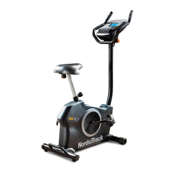
Model No. 831.21913.0
Serial No.
USER’'S MANUAL
Write the serial number in the space
above for reference.
Serial Number Decal
(under frame)
ACTIVATE YOUR
WARRANTY
To register your product and
activate your warranty today, go
to www.nordictrackservice.com/
registration.
CUSTOMER CARE
For service at any time, go to
www.nordictrackservice.com.
Or call 1-800-TO-BE-FIT
(1-800-862-3348)
Mon.––Fri. 6 a.m.––6 p.m. MT
Sat. 8 a.m.––4 p.m. MT
Please do not contact the store.
CAUTION
Read all precautions and instruc-
tions in this manual before using
this equipment. Keep this manual
for future reference.
Advertisement
Table of Contents

Related Manuals for NordicTrack Gx 2.7 Bike


Summary of Contents for NordicTrack Gx 2.7 Bike
- Page 1 Model No. 831.21913.0 Serial No. USER’’S MANUAL Write the serial number in the space above for reference. Serial Number Decal (under frame) ACTIVATE YOUR WARRANTY To register your product and activate your warranty today, go to www.nordictrackservice.com/ registration. CUSTOMER CARE For service at any time, go to www.nordictrackservice.com.
-
Page 2: Table Of Contents
User weight must not exceed 275 pounds. This product should always be used on a level surface. This product is not intended for therapeutic use. Replace label if damaged, illegible, or removed. NORDICTRACK is a registered trademark of ICON IP, Inc. -
Page 3: Important Precautions
IMPORTANT PRECAUTIONS WARNING: To reduce the risk of serious injury, read all important precautions and instructions in this manual and all warnings on your exercise bike before using your exercise bike. ICON assumes no responsibility for personal injury or property damage sustained by or through the use of this product. - Page 5 STANDARD SERVICE PLANS...
-
Page 6: Before You Begin
BEFORE YOU BEGIN Thank you for selecting the revolutionary reading this manual, please see the front cover of this NORDICTRACK GX 2.7 exercise bike. Cycling is an manual. To help us assist you, note the product model ® effective exercise for increasing cardiovascular fitness, number and serial number before contacting us. -
Page 7: Part Identification Chart
PART IDENTIFICATION CHART Use the drawings below to identify the small parts needed for assembly. The number in parentheses below each drawing is the key number of the part, from the PART LIST near the end of this manual. The number following the key number is the quantity needed for assembly. -
Page 8: Assembly
ASSEMBLY •• Assembly requires two persons. •• In addition to the included tool(s), assembly requires the following tools: •• Place all parts in a cleared area and remove the one Phillips screwdriver packing materials. Do not dispose of the packing materials until you ... - Page 9 3. Remove and discard the shipping screws and the shipping tube (not shown) on the front of the Frame (50), if necessary. Set a sturdy piece of packing material under the front of the Frame (50). Attach the Front Stabilizer (63) to the Frame (50) with two M8 x 70mm Screws (46).
- Page 10 6. Tip: Avoid pinching the Main Wire Harness (25). Orient the Upright (27) as shown, and hold it on the Frame (50). Attach the Upright (27) with four M8 x 20mm Avoid pinching the Screws (29). Main Wire Harness (25) 7.
- Page 11 8. Orient the Shield Cover (26) as shown, and press it onto the Left and Right Shields (37, 58). 37, 58 9. Orient the Console Cover (3) as shown, and slide it onto the Upright (27). Tip: Avoid pinching the Main Wire Harness (25).
- Page 12 10. Untie and discard the wire tie on the Main Wire Harness (25). Insert the Main Wire Harness upward through the Handlebar (4) as shown. While a second person holds the Console (7) near the Handlebar (4), plug the Main Wire Harness (25) and the Pulse Wire Harness (23) into the receptacles on the Console.
- Page 13 13. Identify the Right Pedal (60). Using an adjustable wrench, firmly tighten the Right Pedal (60) clockwise into the Right Crank Arm (59). Tighten the Left Pedal (32) counterclockwise into the Left Crank Arm (not shown). Adjust the strap on the Right Pedal (60) to the desired position, and press the ends of the strap onto the tabs on the Right Pedal.
-
Page 14: How To Use The Exercise Bike
HOW TO USE THE EXERCISE BIKE HOW TO PLUG IN THE POWER ADAPTER HOW TO ADJUST THE HEIGHT OF THE SEAT IMPORTANT: If the exercise bike has been exposed For effective exercise, the seat should be at the proper to cold temperatures, allow it to warm to room height. - Page 15 HOW TO ADJUST THE ANGLE OF THE HOW TO ADJUST THE PEDAL STRAPS HANDLEBAR To adjust the To adjust the pedal straps, first angle of the pull the ends of handlebar, loosen the straps off the the handlebar tabs on the ped- knob, rotate the als.
- Page 16 CONSOLE DIAGRAM MAKE YOUR FITNESS GOALS A REALITY WITH Upload your workout results to the iFit cloud IFIT.COM and track your accomplishments. With your new iFit-compatible fitness equipment, you can use an array of features on iFit.com to make your Set calorie, time, or distance goals for your fitness goals a reality: workouts.
-
Page 17: Features Of Console
FEATURES OF THE CONSOLE HOW TO USE THE MANUAL MODE The advanced console offers an array of features 1. Begin pedaling or press any button on the designed to make your workouts more effective and console to turn on the console. enjoyable. - Page 18 Distance (Dist.)——This display mode will show When a wireless iFit module the distance that you have pedaled in miles or is connected, the wireless kilometers. symbol at the top of the dis- play will show the strength of Pulse——This display mode will show your heart rate your wireless signal.
- Page 19 If the display does not show your heart rate, make HOW TO USE THE SOUND SYSTEM sure that your hands are positioned as described. Be careful not to move your hands excessively or To play music or audio books through the console to squeeze the contacts tightly.
- Page 20 HOW TO USE AN ONBOARD WORKOUT resistance level and/or target speed is programmed for the next segment, the resistance level and/or 1. Begin pedaling or press any button on the target speed will appear in the display for a few console to turn on the console.
- Page 21 HOW TO USE A SET-A-GOAL WORKOUT Note: The calorie goal is an estimate of the number of calories that you will burn during 1. Begin pedaling or press any button on the the workout. The actual number of calories that console to turn on the console.
-
Page 22: To Use An Ifit Workout
HOW TO USE AN IFIT WORKOUT For more information about the iFit workouts, please see www.iFit.com. You must have an iFit module to use an iFit workout. To purchase an iFit module at any time, go to When you select an iFit workout, the display will www.iFit.com or call the telephone number on the show the duration of the workout and the approxi- front cover of this manual. - Page 23 HOW TO CHANGE CONSOLE SETTINGS Units——The currently selected unit of measurement will appear in the display. To change the unit of 1. Select the settings mode. measurement, press the Enter button repeatedly. To view distance in miles, select ENGLISH. To view To select the settings mode, press the Settings distance in kilometers, select METRIC.
-
Page 24: Fcc Information
FCC INFORMATION This equipment has been tested and found to comply with the limits for a Class B digital device, pursuant to part 15 of the FCC Rules. These limits are designed to provide reasonable protection against harmful interference in a residential installation. This equipment generates, uses, and can radiate radio frequency energy and, if not installed and used in accordance with the instructions, may cause harmful interference to radio communications. -
Page 25: Maintenance And Troubleshooting
MAINTENANCE AND TROUBLESHOOTING Inspect and tighten all parts of the exercise bike regu- Locate the Reed Switch (64). Loosen, but do not larly. Replace any worn parts immediately. remove, the M4 x 19mm Screw (65). To clean the exercise bike, use a damp cloth and a small amount of mild soap. - Page 26 HOW TO ADJUST THE DRIVE BELT Using an M10 socket wrench with an extension (not included), reach into the opening in the bottom of the If you can feel the pedals slip while you are pedaling, Right Shield (58) and tighten the M10 x 50mm Screw even when the resistance is adjusted to the highest (49) a few turns until the Drive Belt (not shown) is tight;...
-
Page 27: Exercise Guidelines
EXERCISE GUIDELINES Burning Fat——To burn fat effectively, you must exer- WARNING: cise at a low intensity level for a sustained period of Before beginning this time. During the first few minutes of exercise, your or any exercise program, consult your physi- body uses carbohydrate calories for energy. - Page 28 SUGGESTED STRETCHES The correct form for several basic stretches is shown at the right. Move slowly as you stretch; never bounce. 1. Toe Touch Stretch Stand with your knees bent slightly and slowly bend forward from your hips. Allow your back and shoulders to relax as you reach down toward your toes as far as possible.
- Page 29 NOTES...
-
Page 30: Part List
PART LIST Model No. 831.21913.0 R0813A Key No. Qty. Description Key No. Qty. Description Handlebar Knob M4 x 19mm Self-tapping Screw M4 x 16mm Screw Left Shield Console Cover Snap Ring Handlebar Bearing Handlebar Cap M4 x 12mm Screw Pulse Sensor Resistance Cable Console Resistance Motor... -
Page 31: Exploded Drawing
EXPLODED DRAWING Model No. 831.21913.0 R0813A... -
Page 32: Ordering Replacement Parts
ORDERING REPLACEMENT PARTS To order replacement parts, please see the front cover of this manual. To help us assist you, be prepared to provide the following information when contacting us: •• the model number and serial number of the product (see the front cover of this manual) ••...