KTM 65 SX Owner's Manual
2014
Hide thumbs
Also See for 65 SX:
- Owner's manual (91 pages) ,
- Owner's handbook manual (28 pages) ,
- Manual (21 pages)
Table of Contents
Advertisement
Quick Links
Advertisement
Table of Contents

Related Manuals for KTM 65 SX


Summary of Contents for KTM 65 SX
- Page 1 OWNER'S MANUAL 2014 65 SX Art. no. 3213028en...
- Page 3 KTM accepts no liability for delivery options, deviations from illustrations and descriptions, as well as misprints and other errors.
-
Page 4: Table Of Contents
TABLE OF CONTENTS 10.4 Adjusting the rebound damping of the shock TABLE OF CONTENTS MEANS OF REPRESENTATION ........4 absorber............23 Symbols used ........... 4 10.5 Measuring rear wheel sag unloaded....23 Formats used............ 4 10.6 Checking the static sag of the shock absorber ..23 SAFETY ADVICE............ - Page 5 TABLE OF CONTENTS 12.2 Adjusting the basic position of the hand brake 20.4.3 Fuel ............78 lever .............. 48 20.5 Fork............... 78 12.3 Checking brake discs........48 20.6 Shock absorber ..........78 12.4 Checking front brake fluid level ......49 20.7 Chassis ............
-
Page 6: Means Of Representation
All work marked with this symbol requires specialist knowledge and technical understanding. In the interest of the safety of your child, have these jobs performed in an authorized KTM workshop. There, your motorcycle will be serviced optimally by specially trained experts using the specialist tools required. -
Page 7: Safety Advice
SAFETY ADVICE Use definition - intended use KTM sport motorcycles are designed and built to withstand the normal stresses and strains of competitive use. The motorcycles com- ply with currently valid regulations and categories of the top international motorsport organizations. -
Page 8: Protective Clothing
Keep the Owner's Manual in an accessible place to enable you to refer to it as needed. If you would like to know more about the vehicle or have questions on the material you read, please contact an authorized KTM dealer. -
Page 9: Important Notes
Guarantee, warranty The work prescribed in the service schedule must be carried out by an authorized KTM workshop only and confirmed in the customer's Service & Warranty Booklet and in the KTM dealer.net; otherwise, all warranty claims will be void. No warranty claims can be consid- ered for damage resulting from manipulations and/or alterations to the vehicle. -
Page 10: View Of Vehicle
VIEW OF VEHICLE View of vehicle, front left (example) 602650-10 Hand brake lever ( p. 11) Rebound damping of fork Clutch lever ( p. 11) Quick release for seat lock Fuel tap ( p. 12) Choke ( p. 12) Shift lever ( p. -
Page 11: View Of Vehicle, Rear Right (Example)
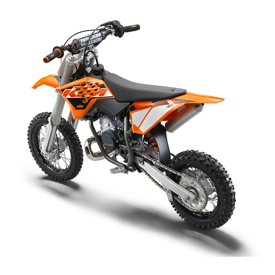
VIEW OF VEHICLE View of vehicle, rear right (example) 602651-10 Filler cap Kill switch ( p. 11) Compression damping of fork Throttle grip ( p. 11) Chassis number ( p. 10) Level viewer, rear brake fluid Shock absorber, compression adjustment Foot brake lever ( p. -
Page 12: Serial Numbers
SERIAL NUMBERS Chassis number The chassis number is stamped on right of the steering head. 602679-10 Engine number The engine number is stamped on the left side of the engine under the engine sprocket. 601938-11 Shock absorber part number The shock absorber part number is stamped on the top of the shock absorber above the adjusting ring on the engine side. -
Page 13: Controls
CONTROLS Clutch lever The clutch lever is fitted on the left side of the handlebar. The clutch is hydraulically operated and self-adjusting. 602653-10 Hand brake lever Hand brake lever is fitted on the right side of the handlebar. The hand brake lever is used to activate the front brake. 602654-10 Throttle grip Throttle grip... -
Page 14: Closing The Filler Cap
CONTROLS Warning Danger of poisoning Fuel is poisonous and a health hazard. – Fuel must not come into contact with the skin, eyes, or clothing. Do not breathe in the fuel vapors. If contact occurs with the eyes, rinse with water immediately and contact a physician. Immediately clean contaminated areas on the skin with soap and water. -
Page 15: Shift Lever
CONTROLS Shift lever Shift lever is mounted on the left side of the engine. 601938-10 The gear positions can be seen in the photograph. The neutral or idle position is between the first and second gears. 601939-10 6.10 Kickstarter The kickstarter is fitted on the right of the engine. -
Page 16: Preparing For Use
When using your motorcycle, remember that others may feel disturbed by excessive noise. – Make sure that the pre-delivery inspection work has been carried out by an authorized KTM workshop. You receive a delivery certificate and the service record at vehicle handover. -
Page 17: Running In The Engine
PREPARING FOR USE – Accustom your child to the handling of the motorcycle on suitable terrain, preferably on a large open meadow. Info To give your child a feel for the brake system, you should push your child at first. Do not start the engine until your child is able to apply the necessary front brake pressure. -
Page 18: Riding Instructions
RIDING INSTRUCTIONS Checks and maintenance measures when preparing for use Info Before each use, check the condition of the vehicle and its operating safety. The vehicle must be in perfect technical condition when it is being operated. – Check the gear oil level. ( p. -
Page 19: Starting Off
Do not change into a low gear at high engine speed. The engine races and the rear wheel can lock up. Info If you hear unusual noises while riding, stop immediately, switch off the engine and contact an authorized KTM workshop. First gear is used for starting off or for steep inclines. -
Page 20: Stopping, Parking
RIDING INSTRUCTIONS Stopping, parking Warning Risk of misappropriation Usage by unauthorized persons. – Never leave the vehicle while the engine is running. Secure the vehicle against use by unauthorized persons. Warning Danger of burns Some vehicle components become very hot when the vehicle is operated. –... -
Page 21: Refueling
RIDING INSTRUCTIONS Refueling Danger Fire hazard Fuel is highly flammable. – Never refuel the vehicle near open flames or burning cigarettes, and always switch off the engine first. Be careful that no fuel is spilt, especially on hot vehicle components. Clean up spilt fuel immediately. –... -
Page 22: Service Schedule
SERVICE SCHEDULE Service schedule Annually Every 80 operating hours Every 40 operating hours Every 20 operating hours Once after 10 operating hours ○ ● ● ● Check the front brake linings. ( p. 50) ○ ● ● ● Check the rear brake linings. ( p. - Page 23 ○ ● ● ● Final inspection: check the vehicle for operating safety and take a test ride. ○ ● ● ● Create a service entry in the KTM DEALER.NET and in the service record. ○ One-time interval ● Periodic interval...
-
Page 24: Tuning The Chassis
Adjusting the compression damping of the shock absorber Caution Danger of accidents Disassembly of pressurized parts can lead to injury. – The shock absorber is filled with high density nitrogen. Adhere to the description provided. (Your authorized KTM workshop will be glad to help.) – Turn adjusting knob counterclockwise all the way. -
Page 25: Adjusting The Rebound Damping Of The Shock Absorber
Adjusting the rebound damping of the shock absorber Caution Danger of accidents Disassembly of pressurized parts can lead to injury. – The shock absorber is filled with high density nitrogen. Adhere to the description provided. (Your authorized KTM workshop will be glad to help.) – Turn adjusting screw clockwise up to the last perceptible click. -
Page 26: Checking The Riding Sag Of The Shock Absorber
Adjusting the spring preload of the shock absorber Caution Danger of accidents Disassembly of pressurized parts can lead to injury. – The shock absorber is filled with high density nitrogen. Adhere to the description provided. (Your authorized KTM workshop will be glad to help.) Preparatory work –... -
Page 27: Adjusting The Riding Sag
TUNING THE CHASSIS 10.9 Adjusting the riding sag Preparatory work – Raise the motorcycle with a lift stand. ( p. 27) – Remove shock absorber. p. 35) – After removing the shock absorber, clean it thoroughly. Main work – Choose and mount a suitable spring. Guideline Spring rate Weight of rider: <... - Page 28 TUNING THE CHASSIS – Position the handlebar. Info Make sure cables and wiring are positioned correctly. – Position the handlebar clamps. Mount and evenly tighten the four screws Guideline Screw, handlebar clamp 20 Nm (14.8 lbf ft) Info Make sure the gap width is even.
-
Page 29: Service Work On The Chassis
SERVICE WORK ON THE CHASSIS 11.1 Raising the motorcycle with a lift stand Note Danger of damage The parked vehicle may roll away or fall over. – Always place the vehicle on a firm and even surface. – Raise the motorcycle at the frame underneath the engine. Lift stand (59229055000) The tires should no longer be in contact with the ground. -
Page 30: Cleaning The Dust Boots Of The Fork Legs
SERVICE WORK ON THE CHASSIS 11.4 Cleaning the dust boots of the fork legs Preparatory work – Raise the motorcycle with a lift stand. ( p. 27) Main work – Push dust boots of both fork legs downwards. Info The dust boots should remove dust and coarse dirt particles from the inside fork tubes. -
Page 31: Removing The Fork Legs
SERVICE WORK ON THE CHASSIS – Position the fork protection on the left fork leg. Mount and tighten screws Guideline Remaining screws, chassis 10 Nm (7.4 lbf ft) – Position the brake line. Mount clamp – Mount the screws C00024-11 11.7 Removing the fork legs Preparatory work... -
Page 32: Removing The Lower Triple Clamp
SERVICE WORK ON THE CHASSIS – Position brake caliper, mount and tighten screws Guideline Screw, brake caliper 20 Nm Loctite ® 243™ (14.8 lbf ft) – Position the brake line. Mount the clamp and screws C00006-11 Finishing work – Install the front wheel. p. -
Page 33: Installing The Lower Triple Clamp
SERVICE WORK ON THE CHASSIS 11.10 Installing the lower triple clamp Main work – Clean the bearing and sealing elements, check for damage, and grease. High viscosity grease ( p. 83) – Insert the lower triple clamp with the steering stem. Mount the upper steering head bearing. -
Page 34: Checking Play Of Steering Head Bearing
Danger of accidents Unstable vehicle handling from incorrect steering head bearing play. – Adjust the steering head bearing play without delay. (Your authorized KTM workshop will be glad to help.) Info If the bike is ridden with play in the steering head bearing, the bearing and the bearing seats in the frame can become dam- aged over time. -
Page 35: Adjusting The Play Of The Steering Head Bearing
SERVICE WORK ON THE CHASSIS » If click positions are noticeable: – Adjust the play of the steering head bearing. p. 33) – Check the steering head bearing and replace if required. Finishing work – Remove the motorcycle from the lift stand. ( p. -
Page 36: Installing The Start Number Plate
SERVICE WORK ON THE CHASSIS 11.15 Installing the start number plate – Position the start number plate with the drill holes onto the holding lugs of the fender. 602673-10 – Mount and tighten screw Guideline Remaining screws, chassis 10 Nm (7.4 lbf ft) –... -
Page 37: Removing The Shock Absorber
SERVICE WORK ON THE CHASSIS 11.18 Removing the shock absorber Preparatory work – Raise the motorcycle with a lift stand. ( p. 27) Main work – Remove screw and lower the rear wheel with the swingarm as far as possible without blocking the rear wheel. -
Page 38: Removing The Air Filter
SERVICE WORK ON THE CHASSIS – Close quick release 602681-11 11.22 Removing the air filter Note Engine failure Unfiltered intake air has a negative effect on the service life of the engine. – Never ride the vehicle without an air filter since dust and dirt can get into the engine and result in increased wear. Warning Environmental hazard Hazardous substances cause environmental damage. -
Page 39: Cleaning The Air Filter And Air Filter Box
SERVICE WORK ON THE CHASSIS 11.24 Cleaning the air filter and air filter box Warning Environmental hazard Hazardous substances cause environmental damage. – Oil, grease, filters, fuel, cleaners, brake fluid, etc., should be disposed of as stipulated in applicable regulations. Info Do not clean the air filter with fuel or petroleum since these substances attack the foam. -
Page 40: Changing The Glass Fiber Yarn Filling Of The Main Silencer
SERVICE WORK ON THE CHASSIS – Mount and tighten screw Guideline Remaining screws, chassis 10 Nm (7.4 lbf ft) 602684-11 11.27 Changing the glass fiber yarn filling of the main silencer Warning Danger of burns The exhaust system gets very hot when the vehicle is driven. –... -
Page 41: Installing The Fuel Tank
SERVICE WORK ON THE CHASSIS Main work – Remove screw 602686-10 – Remove screws 602687-10 – Pull off fuel hose Info Remaining fuel may run out of the fuel hose. – Pull both spoilers off of the side of the radiator bracket and lift off the fuel tank. 601955-11 11.29 Installing the fuel tank... -
Page 42: Removing The Chain Guard
SERVICE WORK ON THE CHASSIS – Mount and tighten screws Guideline Remaining screws, chassis 10 Nm (7.4 lbf ft) 602687-10 – Mount and tighten screw Guideline Remaining screws, chassis 10 Nm (7.4 lbf ft) – Position the fuel tank breather. 602686-11 Finishing work –... -
Page 43: Checking Chain Dirt
SERVICE WORK ON THE CHASSIS 11.32 Checking chain dirt – Check the chain for coarse dirt accumulation. » If the chain is very dirty: – Clean the chain. ( p. 41) 400678-01 11.33 Cleaning the chain Warning Danger of accidents Oil or grease on the tires reduces their grip. –... -
Page 44: Adjusting The Chain Tension
SERVICE WORK ON THE CHASSIS Main work – Push the chain at the end of the chain sliding component upward to measure the chain tension Info The upper chain section must be taut. Because chain wear is not always even, repeat this measurement at differ- ent chain positions. -
Page 45: Checking The Chain, Rear Sprocket, Engine Sprocket, And Chain Guide
SERVICE WORK ON THE CHASSIS 11.36 Checking the chain, rear sprocket, engine sprocket, and chain guide Preparatory work – Raise the motorcycle with a lift stand. ( p. 27) – Remove the chain guard. ( p. 40) Main work – Check the rear sprocket and engine sprocket for wear. -
Page 46: Adjusting The Chain Guide
SERVICE WORK ON THE CHASSIS – Check the chain sliding piece for wear. » If the lower edge of the chain pins is in line with or below the chain sliding piece: – Change the chain sliding piece. – Check the chain sliding piece for tightness. »... -
Page 47: Checking The Frame
If the frame exhibits cracking or deformation due to a mechanical impact: – Change the frame. Info A frame that has been damaged due to a mechanical impact must always be changed. Repair of the frame is not authorized by KTM. 601599-01 11.39 Checking the swingarm –... -
Page 48: Additionally Securing The Rubber Grip
SERVICE WORK ON THE CHASSIS 11.42 Additionally securing the rubber grip Preparatory work – Check the rubber grip. ( p. 45) Main work – Secure the rubber grip at two locations with the retaining wire. Securing wire (54812016000) Wire twister forceps (U6907854) The twisted wire ends face away from the palms and are bent in toward the rubber grip. - Page 49 SERVICE WORK ON THE CHASSIS – Move the clutch fluid reservoir mounted on the handlebar to a horizontal position. – Remove screws – Remove cover with diaphragm 602689-10 – Fill bleeding syringe with the appropriate hydraulic fluid. Bleed syringe (50329050000) Hydraulic fluid (15) ( p.
-
Page 50: Brake System
Danger of accidents Reduced braking efficiency due to worn brake disc(s). – Change the worn brake disc(s) without delay. (Your authorized KTM workshop will be glad to help.) – Check the thickness of the front and rear brake discs at several places on the disc... -
Page 51: Checking Front Brake Fluid Level
Warning Danger of accidents Reduced braking efficiency due to old brake fluid. – Change the brake fluid of the front and rear brake according to the service schedule. (Your authorized KTM workshop will be glad to help.) Warning Environmental hazard Hazardous substances cause environmental damage. -
Page 52: Checking The Front Brake Linings
Warning Danger of accidents Reduced braking efficiency due to old brake fluid. – Change the brake fluid of the front and rear brake according to the service schedule. (Your authorized KTM workshop will be glad to help.) Warning Environmental hazard Hazardous substances cause environmental damage. -
Page 53: Changing The Front Brake Linings
Warning Danger of accidents Reduced braking efficiency due to old brake fluid. – Change the brake fluid of the front and rear brake according to the service schedule. (Your authorized KTM workshop will be glad to help.) Warning Environmental hazard Hazardous substances cause environmental damage. -
Page 54: Installing The Front Brake Linings
Brake linings available from accessory suppliers are often not tested and approved for use on KTM vehicles. The construc- tion and friction factor of the brake linings and therefore the brake power can differ considerably from the original KTM brake linings. If brake linings are used that differ from the originals, there is no guarantee that they comply with the origi- nal license. -
Page 55: Adjusting The Free Travel Of The Foot Brake Lever
BRAKE SYSTEM – Disconnect spring – Move the foot brake lever back and forth between the end stop and the foot brake cylinder piston bracket and check free travel Guideline Free travel of foot brake lever 3… 5 mm (0.12… 0.2 in) »... -
Page 56: Checking Rear Brake Fluid Level
Warning Danger of accidents Reduced braking efficiency due to old brake fluid. – Change the brake fluid of the front and rear brake according to the service schedule. (Your authorized KTM workshop will be glad to help.) – Stand the vehicle upright. -
Page 57: Checking The Rear Brake Linings
Warning Danger of accidents Reduced braking efficiency due to old brake fluid. – Change the brake fluid of the front and rear brake according to the service schedule. (Your authorized KTM workshop will be glad to help.) Warning Environmental hazard Hazardous substances cause environmental damage. -
Page 58: Removing Rear Brake Linings
Removing rear brake linings Warning Danger of accident Brake system failure. – Maintenance work and repairs must be carried out professionally. (Your authorized KTM workshop will be glad to help.) Preparatory work – Raise the motorcycle with a lift stand. ( p. -
Page 59: Installing The Rear Brake Linings
Brake linings available from accessory suppliers are often not tested and approved for use on KTM vehicles. The construc- tion and friction factor of the brake linings and therefore the brake power can differ considerably from the original KTM brake linings. If brake linings are used that differ from the originals, there is no guarantee that they comply with the origi- nal license. -
Page 60: Wheels, Tires
WHEELS, TIRES 13.1 Removing the front wheel Preparatory work – Raise the motorcycle with a lift stand. ( p. 27) Main work – Remove screw 601956-10 – Loosen screw – Hold the front wheel and pull out wheel spindle . Take the front wheel out of the fork. -
Page 61: Removing The Rear Wheel
WHEELS, TIRES 13.3 Removing the rear wheel Preparatory work – Raise the motorcycle with a lift stand. ( p. 27) – Remove the chain guard. ( p. 40) Main work – Remove nut – Remove washer and chain adjuster 700439-01 –... -
Page 62: Checking The Tire Condition
Danger of accidents Instable handling due to incorrect spoke tension. – Ensure that the spoke tension is correct. (Your authorized KTM workshop will be glad to help.) Info A loose spoke can cause wheel imbalance, which leads to more loose spokes in a short time. - Page 63 WHEELS, TIRES – Briefly strike each spoke with the blade of a screwdriver. Info The frequency of the tone depends on the spoke length and diameter. If you hear different tone frequencies from spokes of the same length and thickness, this is an indication that the spoke tension differs. You should hear a high note.
-
Page 64: Cooling System
COOLING SYSTEM 14.1 Cooling system The water pump in the engine forces the coolant to flow. The pressure resulting from the warming of the cooling system is regulated by a valve in the radiator cap . This ensures that operating the vehicle at the specified coolant temperature will not result in a risk of malfunctions. -
Page 65: Checking The Coolant Level
COOLING SYSTEM 14.3 Checking the coolant level Warning Danger of scalding During motorcycle operation, the coolant gets very hot and is under pressure. – Do not remove the radiator cap, radiator hoses or other cooling system components when the engine is hot. Allow the engine and cooling system to cool down. -
Page 66: Refilling The Coolant
COOLING SYSTEM 14.5 Refilling the coolant Warning Danger of poisoning Coolant is poisonous and a health hazard. – Coolant must not come into contact with the skin, eyes, or clothing. If contact occurs with the eyes, rinse with water imme- diately and contact a physician. Immediately clean contaminated areas on the skin with soap and water. If coolant is swal- lowed, contact a physician immediately. -
Page 67: Tuning The Engine
TUNING THE ENGINE 15.1 Checking the play in the throttle cable – Check the throttle grip for smooth operation. – Move the handlebar to the straight-ahead position. Move the throttle grip back- wards and forwards to ascertain play in the throttle cable. Play in gas throttle cable 3…... -
Page 68: Carburetor - Adjusting The Idle Speed
TUNING THE ENGINE 15.4 Carburetor - adjusting the idle speed – Screw in idle air adjusting screw all the way and turn it to the specified basic position. Guideline Idle air adjusting screw Open 3.5 turns – Run the engine until warm. Guideline ≥... - Page 69 TUNING THE ENGINE Info Carry out this work with a cold engine. Water in the float chamber results in malfunctioning. Preparatory work – Turn the knurled screw on the fuel tap all the way clockwise. No more fuel flows from the tank to the carburetor. Main work –...
-
Page 70: Service Work On The Engine
SERVICE WORK ON THE ENGINE 16.1 Checking the gear oil level Info The gear oil level must be checked while the engine is cold. Preparatory work – Stand the motorcycle upright on a horizontal surface. Main work – Remove the screw from the opening used to check the gear oil level. -
Page 71: Filling Up With Gear Oil
SERVICE WORK ON THE ENGINE Main work – Place a suitable container under the engine. – Remove gear oil drain plug with magnet. – Completely drain the gear oil. – Clean the gear oil drain plug with the magnet thoroughly. –... - Page 72 SERVICE WORK ON THE ENGINE Danger Danger of poisoning Exhaust gases are toxic and inhaling them may result in unconsciousness and/or death. – When running the engine, always make sure there is sufficient ventila- tion, and do not start or run the engine in an enclosed space without an effective exhaust extraction system.
-
Page 73: Cleaning, Care
CLEANING, CARE 17.1 Cleaning motorcycle Note Material damage Damage and destruction of components by high-pressure cleaning equipment. – When cleaning the vehicle with a pressure cleaner, do not point the water jet directly onto electrical components, connectors, cables, bearings, etc. Maintain a minimum distance of 60 cm between the nozzle of the pressure cleaner and the component. Excessive pressure can cause malfunctions or destroy these parts. -
Page 74: Storage
60) – Store the vehicle in a dry location that is not subject to large fluctuations in tem- perature. Info KTM recommends raising the motorcycle. – Raise the motorcycle with a lift stand. ( p. 27) – Cover the vehicle with a tarp or similar cover that is permeable to air. -
Page 75: Troubleshooting
TROUBLESHOOTING Faults Possible cause Action – Engine turns but does not start Operating error Go through the steps of starting the engine. p. 16) – Motorcycle was out of use for a long Empty the carburetor float chamber. time and there is old fuel in the float p. - Page 76 TROUBLESHOOTING Faults Possible cause Action – Engine overheats Radiator fins very dirty Clean radiator fins. – Foam formation in cooling system Drain the coolant. p. 63) – Refill the coolant. p. 64) – Damaged cylinder head or cylinder Check the cylinder head or cylinder head gas- head gasket ket.
-
Page 77: Technical Data
TECHNICAL DATA 20.1 Engine Design 1-cylinder 2-stroke engine, water-cooled, with reed intake and exhaust control Displacement 64.85 cm³ (3.9574 cu in) Stroke 40.8 mm (1.606 in) Bore 45 mm (1.77 in) Idle speed 1,400… 1,500 rpm Control Exhaust control PCEV (Pneumatic Controlled Exhaust Valve) Crankshaft bearing 2 grooved ball bearings Conrod bearing... -
Page 78: Carburetor
TECHNICAL DATA – Screw, gear oil level check 6 Nm (4.4 lbf ft) – Screw, intake flange/reed valve housing M6 10 Nm (7.4 lbf ft) ® Screw, kickstarter stop piece 10 Nm (7.4 lbf ft) Loctite 243™ – Screw, outer clutch cover 10 Nm (7.4 lbf ft) –... -
Page 79: Carburetor Tuning
TECHNICAL DATA 20.3.1 Carburetor tuning 100810-01 M/FT ASL Above sea level TEMP Temperature Idle air adjusting screw open (rotations) Idling jet Jet needle Needle position from above Main jet The carburetor tuning depends on the defined ambient and operating conditions. -
Page 80: Capacities
TECHNICAL DATA 20.4 Capacities 20.4.1 Gear oil Gear oil 0.50 l (0.53 qt.) Engine oil (15W/50) ( p. 81) 20.4.2 Coolant Coolant 0.55 l (0.58 qt.) Coolant ( p. 81) Coolant (mixed ready to use) ( p. 81) 20.4.3 Fuel Fuel tank capacity, approx. -
Page 81: Chassis
60/100 - 14 29M TT 80/100 - 12 50M TT Pirelli SCORPION MX Mid Soft 32 NHS Pirelli SCORPION MX Mid Soft 32 NHS Additional information is available in the Service section under: http://www.ktm.com 20.8 Chassis tightening torques – Spoke nipple M3.5... - Page 82 TECHNICAL DATA – Screw, engine bracket 30 Nm (22.1 lbf ft) – Screw, handlebar clamp 20 Nm (14.8 lbf ft) ® Screw, rear sprocket 25 Nm (18.4 lbf ft) Loctite 243™ ® Screw, tail piece 35 Nm (25.8 lbf ft) Loctite 243™...
- Page 83 SUBSTANCES 2-stroke engine oil According to – JASO FC ( p. 85) Guideline – Only use high quality 2-stroke engine oil of a well-known brand. KTM recommends Motorex ® products. Fully synthetic Supplier Motorex ® – Cross Power 2T Brake fluid DOT 4 / DOT 5.1 According to –...
- Page 84 Hydraulic fluid (15) According to – ISO VG (15) Guideline – Use only hydraulic oil that complies with the specified standard (see specifications on the container) and that possesses the corre- sponding properties. KTM recommends Motorex ® products. Supplier Motorex ® –...
-
Page 85: Auxiliary Substances
AUXILIARY SUBSTANCES Air filter cleaner Guideline – KTM recommends Motorex ® products. Supplier Motorex ® – Twin Air Dirt Bio Remover Chain cleaner Guideline – KTM recommends Motorex ® products. Supplier Motorex ® – Chain Clean Cleaning and preserving materials for metal, rubber and plastic Guideline –... - Page 86 AUXILIARY SUBSTANCES Oil for foam air filter Guideline – KTM recommends Motorex ® products. Supplier Motorex ® – Twin Air Liquid Bio Power Paint cleaner and polish for high-gloss and matte finishes, bare metal and plastic surfaces Guideline – KTM recommends Motorex ®...
- Page 87 STANDARDS JASO FC JASO FC is a classification for a 2-stroke engine oil that was specifically developed for the extreme demands of racing. Thanks to first rate synthetic esters and specially designed additives, superb combustion is achieved even under extreme operating conditions. JASO T903 MA Different technical development directions required a new specification for 4-stroke motorcycles –...
- Page 88 INDEX fluid, changing ......46 INDEX Clutch lever ........11 Accessories .
- Page 89 INDEX draining ....... . . 68 refilling ........69 Safe operation .
- Page 90 INDEX View of vehicle front left ........8 rear right .
- Page 91 *3213028en* 3213028en 03/2013 KTM-Sportmotorcycle AG 5230 Mattighofen/Austria Photo: Mitterbauer/KTM http://www.ktm.com...