Tokyo Hy-Power HL-1.5KFX User Manual
Solid-state hf/50mhz band 1kw linear power amplifier
Hide thumbs
Also See for HL-1.5KFX:
- User manual (44 pages) ,
- User manual (45 pages) ,
- Instruction manual (3 pages)

Related Manuals for Tokyo Hy-Power HL-1.5KFX


Summary of Contents for Tokyo Hy-Power HL-1.5KFX
- Page 1 Users Manual Solid-State HF/50MHz Band 1kW Linear Power Amplifier Model HL-1.5K Tokyo Hy-Power Labs., Inc.
-
Page 2: Table Of Contents
Contents Introduction Cautions Features Specifications AC Line Voltage Front Panel Description Rear Panel Description Chassis Bottom Description Connection & Operation ALC Connection Band Data Cable Connection 9-1 : ICOM DC Voltage Band Data 9-2 : ICOM CI-V 9-3 : Yaesu Band Data 9-4 : Kenwood RS-232C Data Protection Circuits... -
Page 3: Introduction
1. Introduction Thank you for purchasing the HL-1.5KFX. This compact and lightweight desktop HF/50MHz linear power amplifier has a maximum input power of 1.75kW. Our solid-state broadband power amp technology makes it the smallest and lightest in the industry. Typical output power is 1kW PEP/SSB on HF and 650W on 6m band with the drive power of 85-90W. - Page 4 radio with supplied Band Data Cable. Before checking inside the amplifier, be sure to wait a few minutes for the high DC voltage to discharge (monitor Vd meter reading). The potentiometers for RF power detector, protection circuits, FET bias voltage circuit, etc, are precisely adjusted at the factory, and should not be altered. Doing so, would require readjustment with precision measuring instruments.
-
Page 5: Features
3. Features Our solid-state broadband design engineers worked to make the HL-1.5KFX, the lightest and most compact 1kW HF amplifier in the industry. This world-class compact 1kW HF/ 6m amplifier is the easiest to handle and operate. The amplifier is equipped with a newly developed band decoder. The amplifier’s decoder changes bands automatically as the data signal is received from the associated HF transceiver’s frequency... -
Page 6: Specifications
4. Specifications Frequency: 1.8 ~ 28MHz all amateur bands including WARC bands and 50MHz Mode: SSB, CW, RTTY RF Drive: 85W typ. (100W max.) Output Power: HF 1kW PEP max., 900W CW (typ.) 50MHz 650W PEP max. Matching Transceivers for Auto Band Decoder: Most ICOM, Yaesu, Kenwood Drain Voltage: 53V (when no RF drive) -
Page 7: Ac Line Voltage
5. AC Line Voltage Although the amplifier is designed to work with both AC 115V (100-120V) and AC 230V (200- 240V), for stability we recommend operation from AC 230V. The correct AC plug (not included in the package), must be obtained locally due to the AC plug variations worldwide. -
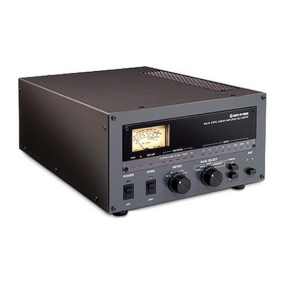
Page 8: 6-A Front Panel Description
6-A. Front Panel Description ‡ I ‡ ‡ ‡ ‡ B ‡ C ‡ E ‡ D ‡ @ ‡ A ‡ @ POWER Main power switch to turn AC power on and off. LED (green) lights when turned on. ‡... - Page 9 turned off immediately after finishing operation. Allow the cooling fan to run for an extended period of time. ‡ F -3 ID: Excessive Id Indicator (>35A). Depending on the band and antenna situation, high drain current may flow into FET’s. If 35A is exceeded, this LED flickers and/ or lights to indicate that high Id is being drawn.
-
Page 10: 6-B Rear Panel Description
6-B. Rear Panel Description ‡ N ‡ L ‡ M ‡ O ‡ G ‡ A ‡ E ‡ F ‡ @ ‡ I ‡ H FUSE FU SE ‡ B ‡ J ‡ K ‡ D ‡ C ‡ @ ANT A RF Output Connector. -
Page 11: 6-C Chassis Bottom Description
ICOM RCA Jack for the DC voltage derived band data cable from the ICOM transceiver. (Reference page 14, Band Data Cable Connection with ICOM.) ‡ J CI-V Earphone jack for CI-V band data cable for ICOM transceivers so equipped. (See page 15.) ‡... -
Page 12: Connection & Operation
Set leads to the failure of the valuable final power FET devices. *** One Antenna System Example TRANSCE IVER Antenna SWR/POW ER METER AC C SE ND TX G ND HL-1.5KFX REAR SEND AN T A INPUT TO AC200V or 100V PLUG Two Antenna System Example TRANSCE IVER 50MHzANTENN SWR / POWER Œ... - Page 13 Connect AC cord and coax cables as illustrated above. Connect the cable from “SEND” to ACC or the remote terminals of transceiver, where it is marked “SEND” or “TX GND”. These terminal pins are shorted to ground when the transceiver is in TX/ON AIR mode. If these connections are not made, the amplifier will not go into TX (amplification) mode.
- Page 14 has shut down the amplifier, check the antenna SWR, Vd , AC line voltage, or try to reduce the drive level. To reset, turn off the POWER switch once, then back on again. The power transformer has an overheat protection in the coil layer. If this temperature switch activates, the amplifier will put you in receive mode with the cooling fan operating until the transformer has cooled off.
-
Page 15: Alc Connection
8. ALC Connection ALC voltage is available at the terminal marked ALC (RCA phono jack) on the right upper corner of the rear panel. Negative maximum DC voltage of ten volts (- 10V) is produced at this terminal when the amplifier is fully driven. -
Page 16: Band Data Cable Connection
METER SEND ACC(2) REMOTE (DIN 7P) ICOMD C VO LTAG E BAND D AT A C AB LE ( DI N 7P • © • ¨ R CA• j HL-1.5KFX REAR VIEW SEND ANTA ICOM (RCA ) INPUT BAND DECODE SW SE LECT "... -
Page 17: Icom Ci-V
9-2 ICOM CI-V The following initial settings are needed on the ICOM transceiver ; CI-V BAUDT RATE 9600 CI-V ADDRESS CI-V TRANSCEIVER CI-V with IC-731 (For details, refer to your ICOM radio manual.) Turn off the power (AC) to both the transceiver and amplifier. Connect the following CI-V band data cable as shown in the illustration. -
Page 18: Yaesu Band Data
9-3 Yaesu Band Data Using the Yaesu band data connection cable (shown below), connect the transceiver (example, FT-1000MP MK-V) to the HL-1.5KFX. Turn off the AC POWER to the transceiver and the amplifier. Connect the 8 pin DIN plug to the BAND DATA (8 pin) socket of the Yaesu transceiver. -
Page 19: Kenwood Rs-232C Data
9-4 Kenwood RS-232C Band Data Using the Kenwood band data connection cable (shown below), connect the transceiver (example TS-950, TS-870) to the HL-1.5KFX as illustrated below. Initial settings for the transceiver are as follows : Communication Speed 9600 (bps) Stop Bit 1 bit ( Refer to the Kenwood radio manual for more details). -
Page 20: Protection Circuits
10. Protection Circuits There are five major protection functions in this amplifier. If the amplifier has shut down for some reason, before re-setting, correct the possible cause of the shut down. Turn off the POWER once and back on to reset. 10-1 O.DRIVE (Over Drive/ Band Miss-set) When the drive power exceeds the 100W level, the amplifier will shut down to STAND-BY mode (or receive) in order to protect the input side of the power FET’s. -
Page 21: Explanations Of Major Circuits
11. Explanation of Major Circuits Five major circuit blocks are explained in there basic form and using signal flows. 11-1 Main DC Power Supply 11-2 Power Amp, L.P.F. 11-3 RF Power Detector, TX/RX Switching 11-4 Main Controller 11-5 Band Decoder, Frequency Counting 11-1 Main DC Power Supply The main DC power supply feeds the 50V DC power to the final PA stage. - Page 22 11-2 Power Amp (PA PC1662V) / L.P.F. (PC1681) The RF PA is the heart of this amplifier and is composed of four SD2933 / THP2933 MOS FET’s. The amplifier is a parallel push-pull type of class AB amplifier. The gate bias supply circuit is regulated for the best stability and is thermally compensated.
-
Page 23: Rf Power Detector, Tx-Rx Switch
11-3 RF Power Detector/ TX-RX Switch (PC1667) As illustrated below, there are two RF power detectors on this board. One detects the drive signal level from the radio and the other monitors the outgoing power and the reflected power from the load (antenna). -
Page 24: Main Control
11-4 Main Control (PCS1699) This is the heart of the control signal processing for the HL-1.5KFX. It judges the operating condition of the amplifier, as well as issuing the commands to the peripheral circuits. Various analog signals are sent to the MPU such as RF drive from the transceiver, RF power signals at various points, DC power supply information, etc. -
Page 25: Band Decoder, Frequency Counter
From these three manufacturers, there are four kinds of band data used in their latest radio models, i.e. DC voltage, 4-bit TTL, RS-232C, and serial data. The HL-1.5KFX is designed to be able to use any of these methods, when the matched cable is connected. -
Page 26: Trouble Shooting
12. Trouble Shooting Failure Possible Cause Solution AC mains not ‡ @ AC fuses blown ‡ @ Replace with new ones. operating ‡ A AC cord not plugged in ‡ A Plug in securely. ‡ B Interlock switch lifting ‡ B Screw bolts tightly on the top cover. ‡... -
Page 27: Appendix
“YAESU”. (For more details, please contact THP.) K3 can be connected to HL-1.5KFX using supplied Yaesu band cable, only if four lines of decimals are connected to DC +5V supply through pull-up resistors (one each 4.7k ohm per each of BCD lines, A, B, C, D.). -
Page 37: Overall Diagram
HL-1.5KFX BLOCK DIAGRAM TOKYO HY-POWER LABS.,INC. -
Page 38: Parts Layout
15. Parts Layout 15-1 Top View (Detailed) SO -2 39(ANT ) CO OL ING FA N PC1 667 RF PO W ER D ET EC TO R PC 1675 PR E-SC AL ER A C PO WE R PC 1681 LP F CON T R OL PO W ER TRA NS FO RM ER PR I M A R Y TAP TE RM I N A L... - Page 40 FUSE F1, F2 (2A x 2)
- Page 42 SURGE AB SORB ER UNIT : PCS1750...
-
Page 43: Rear Panel Connector Connections
HL-1.5KFXREAR PANEL CONNECTOR CONNECTIONS KENWOOD PCS1699 J12 KENWOOD 1 : NC 1 : RX 2 : RX 2 : TX 3 : TX 3 : CTS 4 : NC 4 : RTS 5 : GND 5 : GND 6 : NC 7 : CTS (Rear view) 8 : RTS...