Advertisement
Quick Links
Advertisement

Related Manuals for Tokyo Hy-Power HL-1.1KFX


Summary of Contents for Tokyo Hy-Power HL-1.1KFX
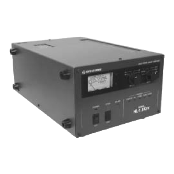
- Page 1 Users Manual Solid-State HF Band 600W Linear Power Amplifier Model HL-1.1K...
- Page 2 Introduction Thank you for purchasing the HL-1.1K This compact and lightweight desktop HF linear power amplifier has a maximum input power of 1.35kW. Our solid-state broadband power amp technology makes it the smallest and lightest in the industry in its class. Typical output power is 600W PEP (SSB, CW) with the drive power of 65-90W.
- Page 3 The amplifier has fast acting sophisticated protection circuits. Please note, however, any such actions that cause the same fault to occur repeatedly, will lead to failure of the valuable final power FET transistors. Before checking inside the amplifier, be sure to wait a few minutes for the high DC voltage to discharge (monitor Vd meter reading).
- Page 4 Features Our solid-state broadband design engineers worked to make the HL-1.1KFX, the lightest and most compact 600W out portable HF amplifier in the industry. This world-class compact 600W HF amplifier is the easiest to handle and operate anywhere in the world.
-
Page 5: Specifications
Specifications Frequency 1.8~29.7 MHz all amateur bands including WARC bands Mode SSB, CW (RTTY) RF Drive 65~90W typ. (100W max.) Output Power 600W PEP typ. (RTTY 400W max.) Drain Voltage Drain Current 30A max. 50 © (unbalanced) Input Impedance 50 © (unbalanced) Output Impedance Final Transistor SD2933 / THP2933 x 4... - Page 6 Otherwise, over-current protection completely shuts down the drain voltage power supply for five minutes before it gets resettable. When this protection works, O.DRIVE lamp lights and HL-1.1KFX will enter the through state, the reset of the amp being disabled for five minutes.
-
Page 7: Front Panel Description
6-A. Front Panel Description TO KY O H Y- PO W ER SO LID STATE LINE ARAM PLI FI ER FA N MET ER BAN D PRO TEC T PO WER O.VO LT FU SE O.HE AT O PER ONAIR O.DR IVE PR MO D E L HL-1. - Page 8 ID (LED) : LED lights when the input drain current is over 20A. This does not mean that any damage occurred to the amplifier, but is useful for the user to notice any stress influencing the final FET caused by high drain current, load impedance trouble, etc.
- Page 9 6-B. Rear Panel Description FUSE IN PUT AN T ALCADJ GN D ST BY ‡M AC POWER : AC Mains Socket. Socket for the AC power cord. (Socket is EMI filtered.) ‡N STBY : RCA Jack. Connect the control cable from the ACC terminal (or SEND, TX GND etc.) of the transceiver.
- Page 10 Inner Layout of HL-1.1KFX U pper View ‡@ RF Power Detector and Send-Receive Switching Relay ‡A Inter-lock Switch ‡B Sub- Power Source Unit ‡C LPF Board ‡D Main Power Source Unit ‡E Sub- Fan (for Main Power Source Unit) ‡F Control Board ‡G Power Amp Unit...
- Page 11 7. Connection and Operation This section explains a one-antenna system connected to the transceiver and an external SWR/POWER meter. KF X REAR S I DE KF X REAR S I DE A N T E N N A T R A N S C E I V E R S W R / P O W E R ME T E R A NT (SE N D,TX G N D )
- Page 12 Turn the POWER switch on. Turn the BAND switch to a desired operating frequency band. Turn the STAND-BY switch to OPER (operate) position and the amplifier is ready to go. If you key the transceiver with the carrier level set relatively low (such as 20-30W), you will achieve an amplified output signal of few hundred watts.
- Page 13 ALC Connection ALC voltage is available at the terminal marked ALC (RCA phono jack) on the right upper corner of the rear panel. Negative maximum DC voltage of ten volts (-10V) is produced at this terminal when the amplifier is fully driven. This voltage is adjustable with the ALC ADJ.
-
Page 14: Protection Circuits
Protection Circuits There are five major protection functions in this amplifier. If the amplifier has shu down for some reason, before re-setting, correct the possible cause of the shut down. Turn off the POWER once and back on to reset. O. - Page 15 10. Explanation of Major Circuits Five major circuit blocks are explained in their basic form and using signal flows. 10-1 Main DC Power Supply 10-2 Power Amp/ L.P.F. 10-3 RF Power Detector/ TX-RX Switching 10-4 Control Board 10-1 Main DC Power Supply The main DC power supply feeds the 50V DC power to the final PA stage.
- Page 16 10-4 Control Board (PC1698) This is the heart of the control signal processing for the HL-1.1KFX. It judges the operating condition of the amplifier, as well as issuing the commands to the peripheral circuits. Various analog signals are processed such as RF drive from the transceiver, RF power signals at various points, DC power supply information, etc.
-
Page 17: Troubleshooting
11. Trouble Shooting Failure Possible Cause Solution AC mains not ‡@ AC fuses blown ‡@ Replace with new ones. operating ‡A AC cord not plugged in ‡A Plug in securely. ‡B Interlock switch lifting ‡C Wrong tap used on ‡B Screw bolts tightly on the top cover. power transformer primary ‡C Correct primary wiring. - Page 18 12. Parts Layout 12-1 Top View (Detailed) 12-2 Top View & Side View 12-3 PA (PC1662V) 12-4 Power Detector (PC1398B) 12-5 Control Board (PC1785) Front View 12-6 Control Board (PC1785) Copper Side 12-7 L.P.F. (PC1399B) 12-8 Frequency Detector Unit (PCS1733) 12-9 Sub DC Unit (PC1784) 13.