Honeywell W7212 Product Data
Economizer logic modules for ventilation control
Hide thumbs
Also See for W7212:
- Product data (32 pages) ,
- Technical reference manual (218 pages) ,
- Manual (36 pages)
Table of Contents
Advertisement
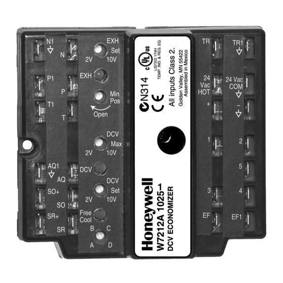
W7212, W7213, W7214
Economizer Logic Modules
FOR VENTILATION CONTROL
APPLICATION
W7212, W7213, and W7214 Economizer Logic Modules are
used with C7232 (CO2) Demand Control Ventilation (DCV)
Sensors, and solid state C7400 Enthalpy Sensors or C7660
Dry Bulb Temperature Sensors. All models proportion outdoor
and return air dampers for control of free cooling in
commercial HVAC equipment.
FEATURES
• Operates from thermostat and DCV (CO2) sensor to
provide a totally integrated control system.
• Solid state control package provides accurate, reliable
and stable control.
• Mounts on M7215 Motor or ductwork.
• Control can be tempered by DCV and fan cycling.
• Used with Honeywell actuators.
• Combines minimum and DCV maximum damper
position potentiometers with compressor staging.
• Solid state enthalpy or dry bulb changeover control.
• Terminals included for switching between Occupied
and Unoccupied operation.
• Terminals included for connecting optional S963B1128
Remote Potentiometer for remote minimum damper
position control.
• LED indicates when free cooling is available.
• LED indicates when module is in DCV mode.
• LED indicates when exhaust fan contact is closed.
• On CO2 sensor failure defaults to DCV maximum
damper position for minimum position.
This feature was added with the series 2 version of the
product. See Table 1.
• W7213 is used with heat pump B terminal.
• W7214 is used with heat pump O terminal.
• W7212C is used for applications requiring low
temperature and humidity and has the "E" enthalpy
curve.
Application ........................................................................
Features ...........................................................................
Specifications ...................................................................
Ordering Information ........................................................
Installation ........................................................................
Settings And Adjustments .................................................
Checkout and Troubleshooting ......................................... 20
PRODUCT DATA
Contents
1
1
2
2
3
8
63-2596-09
Advertisement
Table of Contents

Related Manuals for Honeywell W7212


Summary of Contents for Honeywell W7212
- Page 1 APPLICATION • LED indicates when exhaust fan contact is closed. • On CO2 sensor failure defaults to DCV maximum W7212, W7213, and W7214 Economizer Logic Modules are damper position for minimum position. used with C7232 (CO2) Demand Control Ventilation (DCV)
-
Page 2: Specifications
If you have additional questions, need further information, or would like to comment on our products or services, please write or phone: 1. Your local Honeywell Automation and Control Products Sales Office (check white pages of your phone directory). 2. Honeywell Customer Care... -
Page 3: Location And Mounting
W7212, W7213, W7214 ECONOMIZER LOGIC MODULES Approvals: 3. Installer must be a trained, experienced service Underwriters Laboratories Inc.: UL873 listed. technician. Flammability Rating: UL94-5VB. 4. After installation is complete, check out product Plenum Rated. operation as provided in these instructions. - Page 4 CO2 sensor. The DCV LED lights when the DCV (CO2) signal is above setpoint. If the CO2 sensor should fail, the W7212 will default to the DCV MAX position which is the minimum position design for 100% occupancy of the space.
- Page 5 If not available, use the following guidelines: DCV voltage output at the threshold. 1. Mount sensor in an area with unobstructed air circulation. 2. Connect it to the AQ and AQ1 terminals of the W7212 (see Wiring section for details). COMMERCIAL DISCHARGE...
- Page 6 W7212, W7213, W7214 ECONOMIZER LOGIC MODULES Table 2. Applicable Wiring Diagrams. Actuator Enthalpy Changeover Comments Figure Economizer Honeywell MS7XXX Single Single-stage cooling system. W7212 Single or Differential Two-stage cooling system. Two-stage heat pump system. W7213, W7214 Honeywell M7215 Single Direct mount Logic Module to Motor and W7212 T7300 thermostat.
- Page 7 For single enthalpy control, the module compares outdoor enthalpy to the ABCD setpoint. Power at N terminal determines Occupied/Unoccupied setting: •W7212: 24 Vac (Occupied), no power (Unoccupied). •W7213,W7214: No power (Occupied), 24 Vac (Unoccupied). Modulation is based on the mixed air sensor signal.
- Page 8 Control returns to normal once the MAXIMUM DAMPER Open mixed air temperature rises to 48°F. Some models DEMAND CONTROL of the W7212 close the damper fully and others VENTILATION SETPOINT close the damper to minimum position. Check the LED LIGHTS WHEN DEMAND CONTROL...
- Page 9 W7212, W7213, W7214 ECONOMIZER LOGIC MODULES 4. Ensure that either the factory-installed jumper is in place will return the OA damper to minimum position (this is either across terminals P and P1 or, if remote damper position MIN POS if using a CO2 sensor or DCV MAX if a CO2 sensor is required, that it is wired according to Fig.
- Page 10 (13) (16) (18) (21) (24) (27) (29) (32) (35) (38) (41) (43) APPROXIMATE DRY BULB TEMPERATURE— °F (°C) M11160C HIGH LIMIT CURVE FOR W7210D, W7212, W7213, W7214, W7340B. Fig. 7. W7212A, W7213, W7214 performance characteristics for enthalpy changeover settings. 63-2596—09...
- Page 11 (10) (10) (13) (16) (18) (21) (24) (27) (29) (32) (35) (38) (41) (43) APPROXIMATE DRY BULB TEMPERATURE— °F (°C) M23879A HIGH LIMIT CURVE FOR W7210D, W7212, W7213, W7214, W7340C. Fig. 8. W7212C performance characteristics for enthalpy changeover settings 63-2596—09...
- Page 12 WITH SINGLE-STAGE COOLING SYSTEMS OR SINGLE-STAGE COOLING THERMOSTATS. T7300 TERMINALS A1 AND A2 ARE CONNECTED WHEN COMMERCIAL THERMOSTAT IS IN THE OCCUPIED MODE. EF AND EF1 ARE DRY CONTACTS IN THE LOGIC MODULE. M20716F Fig. 9. W7212 used with M7215 Damper Motor and T7300 Thermostat. 63-2596—09...
- Page 13 FACTORY INSTALLED 620 OHM, 1 WATT, 5% RESISTOR SHOULD NOT BE REMOVED. DIFFERENTIAL ENTHALPY NOT RECOMMENDED FOR USE WITH SINGLE-STAGE COOLING SYSTEMS OR SINGLE-STAGE COOLING THERMOSTATS. EF AND EF1 ARE DRY CONTACTS IN THE LOGIC MODULE. M13657B Fig. 10. W7212 used with M7215 Damper Motor and T7350 Thermostat. 63-2596—09...
- Page 14 FACTORY INSTALLED 620 OHM, 1 WATT, 5% RESISTOR SHOULD NOT BE REMOVED. DIFFERENTIAL ENTHALPY NOT RECOMMENDED FOR USE WITH SINGLE-STAGE COOLING SYSTEMS OR SINGLE-STAGE COOLING THERMOSTATS. M13658B EF AND EF1 ARE DRY CONTACTS IN THE LOGIC MODULE. Fig. 11. W7212 used with M7215 Damper Motor and TB7220 or TB8220 Thermostats. 63-2596—09...
- Page 15 SEE WIRING DIAGRAMS FOR T7350 AND TB7220/TB8220. TIME CLOCK IS AN OPTION TO USING OCCUPIED CONTACTS ON THE COMMERCIAL THERMOSTAT. M13659C Fig. 12. W7212 used in single-stage cooling system with single enthalpy changeover and Honeywell actuator and time clock for occupancy. 63-2596—09...
- Page 16 FACTORY INSTALLED 620 OHM, 1 WATT, 5% RESISTOR SHOULD BE COMMERCIAL THERMOSTAT. REMOVED ONLY WHEN A C7400 ENTHALPY SENSOR IS ADDED TO M13660B SR AND SR+ FOR DIFFERENTIAL ENTHALPY. Fig. 13. W7212 used in two-stage cooling system with Honeywell Series 72 Actuator and time clock for occupancy. 63-2596—09...
- Page 17 SEE WIRING DIAGRAMS FIGS 9 AND 10 FOR T7350 AND TB7220/TB8220. TIME CLOCK IS AN OPTION TO USING OCCUPIED CONTACTS ON THE COMMERCIAL THERMOSTAT. M13661B Fig. 14. W7212 controlling parallel-wired Honeywell Series 72 Actuators and time clock for occupancy. 63-2596—09...
- Page 18 W7212, W7213, W7214 ECONOMIZER LOGIC MODULES MINIMUM POSITION 24 Vac ADJUSTMENT – C7150B DISCHARGE AIR SENSOR MS7XXX HONEYWELL ACTUATOR – 2-10 VDC INDOOR AIR SENSOR W7214 C7400 620 OHM OUTDOOR RESISTOR ENTHALPY SENSOR COOL 1 (HOT) COOL 2 EXHAUST HEAT 2...
- Page 19 COOL 2 COOL 1 VISION COOL 2 PRO IAQ M29973 M29974 Fig. 17. Vision Pro IAQ with EIM connected to a W7212 Economizer (With Morning Warm-up Enabled) Fig. 16. Vision Pro IAQ with EIM connected to a W7459 Economizer 63-2596—09...
-
Page 20: Troubleshooting
CHECKOUT AND TROUBLESHOOTING. JUMPER USED FOR SINGLE ENTHALPY CONTROL. M20612 Fig. 18. Meter location for checkout and troubleshooting (W7212 shown). Table 4. Checkout for W7212, W7213, W7214 Economizers Connected to Honeywell Actuator. Step Checkout Procedure Proper Response CHECKOUT PREPARATION FOR ECONOMIZING ONLY Disconnect power at TR and TR1. - Page 21 W7212, W7213, W7214 ECONOMIZER LOGIC MODULES Table 4. Checkout for W7212, W7213, W7214 Economizers Connected to Honeywell Actuator. (Continued) Step Checkout Procedure Proper Response DIFFERENTIAL ENTHALPY Execute step one, Checkout Preparation. — Turn DCV MAX to mid position. Place 620 ohm resistor across S and + (white sleeve resistor makes OA —...
- Page 22 W7212, W7213, W7214 ECONOMIZER LOGIC MODULES Table 4. Checkout for W7212, W7213, W7214 Economizers Connected to Honeywell Actuator. (Continued) Step Checkout Procedure Proper Response HEAT PUMP INPUT - W7213, W7214 ONLY Execute step one, Checkout Preparation. — Turn DCV MAX to mid position; set enthalpy potentiometer to A.
- Page 23 W7212, W7213, W7214 ECONOMIZER LOGIC MODULES 63-2596—09...
- Page 24 W7212, W7213, W7214 ECONOMIZER LOGIC MODULES Automation and Control Solutions Honeywell International Inc. 1985 Douglas Drive North Golden Valley, MN 55422 Honeywell Limited-Honeywell Limitée 35 Dynamic Drive ® U.S. Registered Trademark Toronto, Ontario M1V 4Z9 © 2010 Honeywell International Inc.