Advertisement
Table of Contents
- 1 Table of Contents
- 2 Application
- 3 Features
- 4 Ordering Information
- 5 Specifications
- 6 Specifications: M7215
- 7 Specifications: W7212A Logic Module
- 8 Installation: M7215, M7415, M8405
- 9 Wiring: M7215, M7415, M8405
- 10 Operation and Checkout
- 11 Settings and Adjustments
- 12 Sequence of Operation
- 13 Operation: W7212
- 14 Settings and Adjustments: W7212
- 15 Checkout and Troubleshooting
- 16 Checkout and Troubleshooting: W7212
- Download this manual
Solid State Economizer System
(CONSISTING OF: C7046C DISCHARGE AIR SENSOR OR C7150B MIXED AIR SENSOR, C7400A
SOLID STATE ENTHALPY SENSOR OR C7650A SOLID STATE TEMPERATURE SENSOR, M7415
OR M8405 DAMPER ACTUATORS OR MODULATING DIRECT COUPLED ACTUATORS (MS7505),
T6031H THERMOSTAT AND W7459 OR W7212 SOLID STATE ECONOMIZER LOGIC MODULE)
C7046C
C7150B
W7459A,C
C7400A/C7650A
APPLICATION
The Solid State Economizer System provides an economical
method of providing cooling air by incorporating outdoor air in
the first stage of cooling in heating, ventilating and air
conditioning (HVAC) systems. The Solid State Economizer
System consists of the C7046C Discharge Air Sensor or
C7150B Mixed Air Sensor, C7400A Solid State Enthalpy
Sensor or C7650A Solid State Temperature Sensor, M7415
or M8405 Damper Actuators or Modulating Direct Coupled
Actuators (MS7505), T6031H Thermostat and W7212 or
W7459A,C Solid State Economizer Logic Module.
Application ........................................................................
Features ...........................................................................
Ordering Information ........................................................
Specifications ...................................................................
Specifications: M7215 ......................................................
Specifications: W7212A Logic Module .............................
Installation: M7215, M7415, M8405 .................................
Wiring: M7215, M7415, M8405 ........................................
Operation and Checkout .................................................. 12
Settings and Adjustments ................................................. 14
M7415/M8405
W7212
T6031H
Contents
FEATURES
C7046C Discharge Air Sensors have probe lengths of 8 in.
(203 mm) and nominal sensor resistance of 3000 ohms at
77°F (25°C).
• No setting or calibration required.
• Solid state components not affected by dust or dirt.
• Fast reacting.
• Rugged aluminum insertion probe.
C7150B Mixed Air Sensor is used with the W7212/W7459
Economizer Module to sense mixed or discharged air in roof-
top packaged air conditioning equipment.
• No setting or calibration required.
C7400A Solid State Enthalpy Sensor and C7650A Solid State
Temperature Sensors are used with the W7212/W7459 Solid
State Economizer Logic Module to sense outdoor and return
air enthalpy or temperature.
• C7400A senses and combines temperature and
humidity (enthalpy) of outdoor air (heat index).
• C7650A senses temperature only.
• When enthalpy/temperature of outdoor air increases,
the outdoor air damper closes to a preset minimum
position.
• When enthalpy/temperature of outdoor air is low, the
outdoor air damper opens to reduce the building
cooling load.
• Additional economizer savings are achieved when two
C7400A Solid State Enthalpy Sensors are connected to
one Logic Module for differential enthalpy changeover
control.
Sequence of Operation .................................................... 16
1
Operation: W7212 ............................................................ 17
1
Settings and Adjustments: W7212 ................................... 18
2
Checkout and Troubleshooting ........................................ 19
3
Checkout and Troubleshooting: W7212 ........................... 31
4
6
7
8
PRODUCT DATA
63-2484-2
Advertisement
Table of Contents

Related Manuals for Honeywell C7150B


Summary of Contents for Honeywell C7150B
-
Page 1: Table Of Contents
Solid State Economizer System (CONSISTING OF: C7046C DISCHARGE AIR SENSOR OR C7150B MIXED AIR SENSOR, C7400A SOLID STATE ENTHALPY SENSOR OR C7650A SOLID STATE TEMPERATURE SENSOR, M7415 OR M8405 DAMPER ACTUATORS OR MODULATING DIRECT COUPLED ACTUATORS (MS7505), T6031H THERMOSTAT AND W7459 OR W7212 SOLID STATE ECONOMIZER LOGIC MODULE) -
Page 2: Ordering Information
If you have additional questions, need further information, or would like to comment on our products or services, please write or phone: 1. Your local Honeywell Automation and Control Products Sales Office (check white pages of your phone directory). 2. Honeywell Customer Care... -
Page 3: Specifications
40°F to 150°F (4°C to 66°C). Wiring Connections: 6 in. (152 mm) leadwires. Dimensions: See Fig. 1. C7150B Mixed Air Sensor Used to sense mixed air in rooftop packaged air conditioning equipment. Resistance/Temperature (NTC): Nominal Resistance: 3000 ohms at 77°F (24°C). Nominal Sen- sitivity: 70 ohms per degree F (124 ohms per degree C) at midrange. -
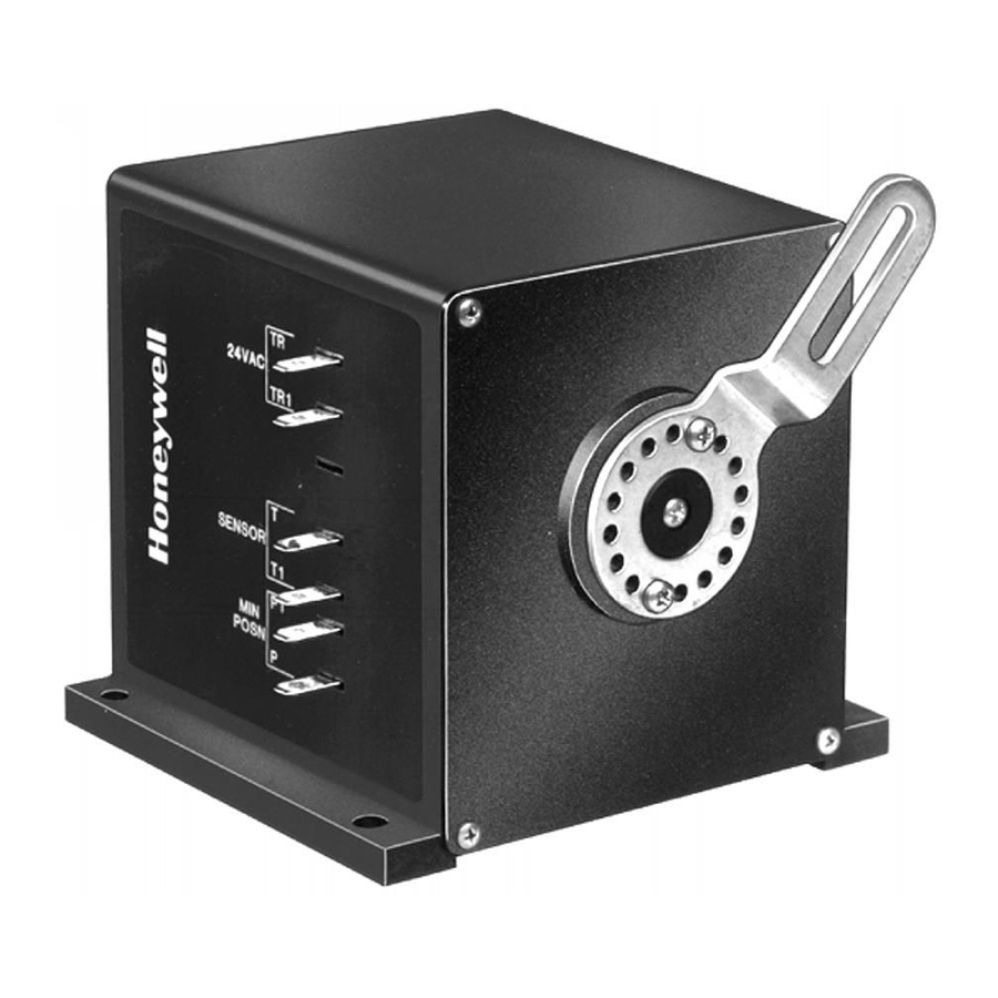
Page 4: Specifications: M7215
SOLID STATE ECONOMIZER SYSTEM 2-1/2 (64) Fig. 2. Approximate dimensions of C7150B Mixed/ Discharge Air Sensor in in. (mm). 5/16 (8) 3-5/32 (80) 2-3/4 (70) 9/16 7/32 (14) 1 (25) Fig. 3. Approximate dimensions of C7400A Solid State Enthalpy Sensor/C7650A Solid State Temperature Sensor in in. - Page 5 Shaft: Single-ended drive shaft with crank arm supplied. Reliability: Full-Stroke Cycles: 60,000. Repositions: 1,500,000. 4-1/2 (114) 2-1/4 (57) 7/16 3-1/2 (89) (11) 5-3/16 (132) TOP VIEW Fig. 4. M7215, M7415A, and M8405A Damper Motor dimensions in in. (mm). Power (Vac) Voltage (Vac) Model Number 50/60 Hz...
-
Page 6: Specifications: W7212A Logic Module
2-1/8 (54) M9090 Fig. 6. Approximate dimensions of W7459 Solid State SPECIFICATIONS: W7212A LOGIC MODULE Models: W7212A, W7213A, W7214A Logic Modules: for use with any Honeywell 2-10 Vdc actuator; includes DCV input; adjustable exhaust fan setpoint. NOTES: — — Dimensions: See Fig. 7. -
Page 7: Installation: M7215, M7415, M8405
Plenum Rated. C-tick. Accessories: 4074EJM Bag Assembly. Consists of: Checkout jumper, 620 ohm, 1.2K ohm, 5.6K ohm, and 6.8K ohm checkout resis- tors. C7046A Discharge Air Temperature Sensor. C7150B Mixed Air Temperature Sensor. C7232A,B Carbon Dioxide Sensors. Control Range Model Number °F... -
Page 8: Wiring: M7215, M7415, M8405
SOLID STATE ECONOMIZER SYSTEM CAUTION Personal Injury Hazard. Spring-return assembly can release. Leave end covers attached to the motor. Location and Mounting Locate motor as close as possible to the equipment to be controlled. Refer to Fig. 4 for mounting dimensions. 1. - Page 9 To mount the C7046C Sensor in a junction box (see Fig. 11): 1. Cut a 1/2 in. (13 mm) hole in the duct or plenum surface at the desired location. 2. Remove the center rear knockout from the junction box and insert the sensor probe through the knockout with the flange flat against the junction box.
- Page 10 SOLID STATE ECONOMIZER SYSTEM IMPORTANT Failure to follow these wiring practices can introduce electrical interference (noise) that can cause erratic system operation: a. Keep wiring at least one foot away from large induc- tive loads such as motors, line starters, lighting bal- lasts, and large power distribution panels.
- Page 11 Wiring CAUTION Can Cause Electrical Shock or Equipment Damage. Disconnect power supply before connecting wiring. Disconnect the power supply before connecting wiring to prevent electrical shock and equipment damage. All wiring must comply with applicable local codes and ordinances. Refer to Fig. 13 and the wiring diagrams furnished with the system equipment to complete the wiring.
-
Page 12: Operation And Checkout
C7046C (Discharge) and C7150B (Mixed) Air Sensors The C7046C discharge air sensor is applied following the coils in the supply air to the conditioned space. The C7150B mixed air sensor is mounted in the mixing box, where the “best” combination of outdoor and return air temperature can be measured. - Page 13 CONTROL CONTROL POINT CURVE APPROX. °F (°C) AT 50% RH 73 (23) 70 (21) 67 (19) 63 (17) APPROXIMATE DRY BULB TEMPERATURE— °F (°C) HIGH LIMIT CURVE FOR W7210D, W7212, W7213, W7214, W7340B. Fig. 18. Partial psychrometric chart with single C7400A Solid State Enthalpy Sensor and W7212 or W7459 Solid State Economizer Logic Module performance curves.
-
Page 14: Settings And Adjustments
M7415 Damper Actuator Single M7415 Damper Actuator accepts thermistor sensor input from a C7046A or a C7150B Mixed Air Sensor mounted in discharge or mixed air duct. See Fig. 27. During the occupied period, on a call for cooling, when outdoor air temperature or enthalpy conditions are low, the M7415 Actuator proportions to maintain between 50°F (10°C) and... - Page 15 This temperature range can be adjusted either up or down by wiring a resistor in series (to increase the setpoint) or in parallel (to decrease the setpoint) with the C7150B, depending on the application. See Fig. 21 and 22 for explanation.
-
Page 16: Sequence Of Operation
SOLID STATE ECONOMIZER SYSTEM The setpoint scale markings, located on the W7459, are A,B,C and D. Turn the setpoint potentiometer fully clockwise to the D setting. The economizer selects the air that has lower enthalpy or temperature for cooling; for example, if outdoor air has lower enthalpy or temperature than return air, the outdoor air damper is opened to bring in outdoor air for free cooling. -
Page 17: Operation: W7212
OPERATION: W7212 The purpose of the economizer is to use outdoor air for cooling, whenever possible, to reduce compressor operation. Power at the N terminal determines the Occupied/Unoccupied setting: — W7212: • 24 Vac (Occupied). • No power (Unoccupied). — W7213,W7214: •... -
Page 18: Settings And Adjustments: W7212
SOLID STATE ECONOMIZER SYSTEM NOTES: — DCV and Free Cooling have setpoints and LED indications. — For models with a B terminal (W7213): No power to B: cooling mode, free cool enabled. Module follows logic detailed above. 24V power to B: heating mode, free cool disabled. Actuator drives to minimum position (closed when Unoccupied). —... -
Page 19: Checkout And Troubleshooting
7. If all minimum and maximum position adjustments are complete, remove the T-T1 jumper and reconnect the mixed air sensor. EQUATION 1. FORMULA TO AID MINIMUM POSITION ADJUSTMENT. × OA)+(T × RA)= T Where: = Outdoor air temperature OA = Percent of outdoor air = Return air temperature RA = Percent of return air = Resulting mixed air temperature... - Page 20 SOLID STATE ECONOMIZER SYSTEM M8405 APPLY 24VAC T-X FOR MIN POSN C7400 T-D FOR OUTDOOR MAX POSN SENSOR C7400 RETURN SENSOR UNOCCUPIED OCCUPIED T675/T6031 MIXED AIR CONTROL 55¡ F SETPOINT T7300 OR T874 THERMOSTAT POWER SUPPLY. PROVIDE DISCONNECT MEANS AND OVERLOAD PROTECTION AS REQUIRED. MOTOR SPRING-RETURNS CLOSED WHEN FAN IS NOT RUNNING.
- Page 21 C7400 OUTDOOR ENTHALPY SENSOR 620 OHM RESISTOR C7150B MIXED AIR OR C7046A UNOCCUPIED DISCHARGE ST6008 AIR SENSOR TIMER OCCUPIED T7300 OR T874 THERMOSTAT POWER SUPPLY. PROVIDE DISCONNECT MEANS AND OVERLOAD PROTECTION AS REQUIRED. MOTOR SPRING-RETURNS CLOSED WHEN FAN IS NOT RUNNING.
- Page 22 SOLID STATE ECONOMIZER SYSTEM C7150B MIXED AIR OR C7046A DISCHARGE AIR SENSOR 0/2-10 VDC INDOOR AIR SENSOR C7400 OUTDOOR ENTHALPY SENSOR T7300/Q7300 THERMOSTAT POWER SUPPLY. PROVIDE DISCONNECT MEANS AND OVERLOAD PROTECTION AS REQUIRED. ENSURE THAT TRANSFORMER IS SIZED TO HANDLE THE EXTRA LOAD OF THE ECONOMIZER AND ACTUATOR. USE THE SAME TRANSFORMER FOR T7300 AND ECONOMIZER.
- Page 23 C7150B MIXED AIR OR C7046A DISCHARGE AIR SENSOR – 0/2-10 VDC INDOOR AIR SENSOR C7400 OUTDOOR ENTHALPY SENSOR T7350 THERMOSTAT POWER SUPPLY. PROVIDE DISCONNECT MEANS AND OVERLOAD PROTECTION AS REQUIRED. ENSURE THAT TRANSFORMER IS SIZED TO HANDLE THE EXTRA LOAD OF THE ECONOMIZER AND ACTUATOR.
- Page 24 SOLID STATE ECONOMIZER SYSTEM C7150B MIXED AIR OR C7046A DISCHARGE AIR SENSOR 0/2-10 VDC INDOOR AIR SENSOR C7400 OUTDOOR ENTHALPY SENSOR TB7220 OR TB8220 THERMOSTAT POWER SUPPLY. PROVIDE DISCONNECT MEANS AND OVERLOAD PROTECTION AS REQUIRED. ENSURE THAT TRANSFORMER IS SIZED TO HANDLE THE EXTRA LOAD OF THE ECONOMIZER AND ACTUATOR.
- Page 25 EF AND EF1 ARE DRY CONTACTS IN THE LOGIC MODULE. SEE WIRING DIAGRAMS FOR T7350 AND TB7220/TB8220. TIME CLOCK IS AN OPTION TO USING OCCUPIED CONTACTS ON THE THERMOSTAT. Fig. 32. W7212A used in single-stage cooling system with single enthalpy changeover and Honeywell actuator and time MINIMUM POSITION ADJUSTMENT –...
- Page 26 FACTORY INSTALLED 620 OHM, 1 WATT, 5% RESISTOR SHOULD BE REMOVED ONLY WHEN A C7400 ENTHALPY SENSOR IS ADDED TO SR AND SR+ FOR DIFFERENTIAL ENTHALPY. Fig. 33. W7212A used in two-stage cooling system with Honeywell Series 72 Actuator and time clock for occupancy. 63-2484—2 MINIMUM POSITION ADJUSTMENT –...
- Page 27 SEE WIRING DIAGRAMS FOR T7350 AND TB7220/TB8220. TIME CLOCK IS AN OPTION TO USING OCCUPIED CONTACTS ON THE THERMOSTAT. Fig. 34. W7212 controlling parallel-wired Honeywell Series 72 Actuators and time clock for occupancy. MINIMUM POSITION ADJUSTMENT C7150B MIXED AIR OR C7046A...
- Page 28 T7300 TERMINALS A2 AND A3 ARE CONNECTED WHEN THERMOSTAT IS IN THE UNOCCUPIED MODE. SEE WIRING DIAGRAMS FOR T7350 AND TB7220/TB8220. W7213: B TERMINAL W7214: O TERMINAL Fig. 35. W7213, W7214 controlling heat pump system. 63-2484—2 MINIMUM POSITION ADJUSTMENT C7150B DISCHARGE AIR SENSOR – 0/2-10 VDC INDOOR AIR SENSOR 620 OHM...
- Page 29 Table 6. Troubleshooting modulating economizer—outdoor enthalpy above setpoint. Condition on Logic Module Should Be 1. Red LED not lighted. 2. 24 Vac to terminals {TR} and {TR1}. 3. 24 Vac to terminals {1} and {TR1}. 4. 24 Vac to terminals {2} and {TR1}. 5.
- Page 30 SOLID STATE ECONOMIZER SYSTEM Table 8. Troubleshooting three-position economizer—outdoor enthalpy above setpoint. Condition on Logic Module Should Be 1. Red LED not lighted. 2. 24 Vac to terminals {TR} and {TR1}, {X} and {TR}. 3. 24 Vac to terminals {1} and {TR}. 4.
-
Page 31: Checkout And Troubleshooting: W7212
Excessive force can damage potentiometer controls. Use a small screwdriver when adjusting enthalpy changeover and minimum damper position controls. Table 10. Checkout for W7212, W7213, W7214 Economizers Connected to Honeywell Actuator. Step Checkout Procedure CHECKOUT PREPARATION Disconnect power at TR and TR1. - Page 32 SOLID STATE ECONOMIZER SYSTEM Table 10. Checkout for W7212, W7213, W7214 Economizers Connected to Honeywell Actuator. (Continued) Step Checkout Procedure DCV AND EXHAUST Execute step one, Checkout Preparation. Ensure terminals AQ and AQ1 are open. Connect 9V battery positive to AQ and negative to AQ1.